Downloaded 391 times
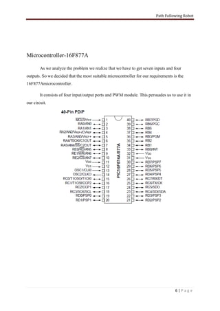
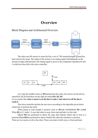
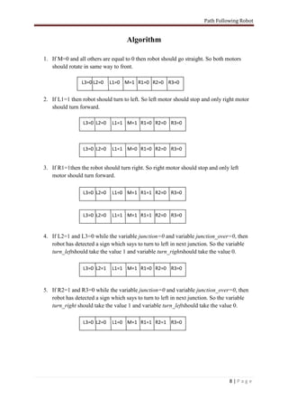
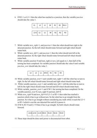
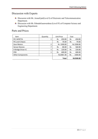

The document describes a path following robot project created by engineering students. It uses IR sensors to detect a black path on a white surface and a PIC microcontroller to process sensor inputs and control motors to follow the path. It provides a block diagram of the robot's components and architecture. It also details the algorithm used by the microcontroller to determine motor movements based on sensor readings to navigate straight paths and turns.