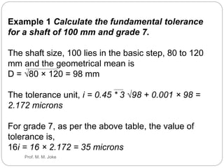
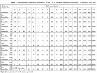
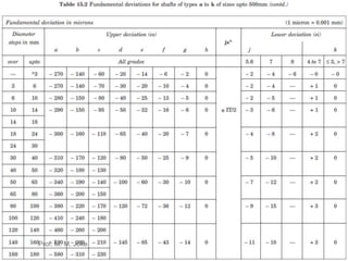
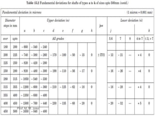
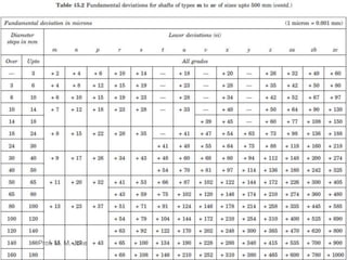
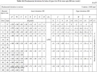
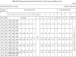
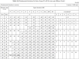
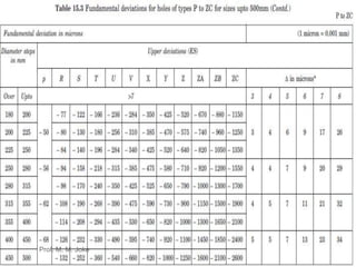
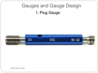
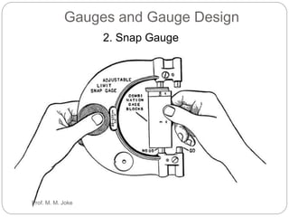
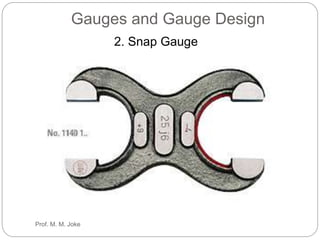
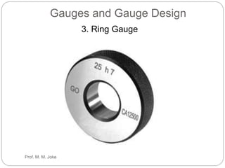
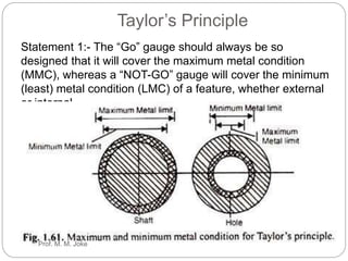
Limits, Fits and
Tolerances
Chapter 3
Prof. M. M. Joke
Graphical Illustration of Tolerance
Zones
Prof. M. M. Joke
IT5 IT6 IT7 IT8 IT9 IT10 IT11 IT12 IT13 IT14 IT15 IT16
7i 10i 16i 25i 40i 64i 100i 160i 250i 400i 640i 1000
i
Relative magnitude of IT tolerances for grades 5 to 16 in terms
of tolerance unit i for sizes upto 500 mm
The fundamental tolerance is a function of the nominal size
and its unit is given by the emperical relation, standard
tolerance unit,
i = 0.45 × 3 √D + 0.001 D
where i is in microns and D is the geometrical mean of the
limiting values of the basic steps mentioned above, in
millimetres. This relation is valid for grades 5 to 16 and
nominal sizes
from 3 to 500 mm.
Prof. M. M. Joke
Example 1 Calculate the fundamental tolerance
for a shaft of 100 mm and grade 7.
The shaft size, 100 lies in the basic step, 80 to 120
mm and the geometrical mean is
D = √80 × 120 = 98 mm
The tolerance unit, i = 0.45 * 3 √98 + 0.001 × 98 =
2.172 microns
For grade 7, as per the above table, the value of
tolerance is,
16i = 16 × 2.172 = 35 microns
Prof. M. M. Joke
Prof. M. M. Joke
Prof. M. M. Joke
Prof. M. M. Joke
Prof. M. M. Joke
Prof. M. M. Joke
Prof. M. M. Joke
Prof. M. M. Joke
Prof. M. M. Joke
Prof. M. M. Joke
Gauges and Gauge Design
1. Plug Gauge
Prof. M. M. Joke
Gauges and Gauge Design
1. Plug Gauge
Prof. M. M. Joke
Gauges and Gauge Design
2. Snap Gauge
Prof. M. M. Joke
Gauges and Gauge Design
2. Snap Gauge
Prof. M. M. Joke
Gauges and Gauge Design
2. Snap Gauge
Prof. M. M. Joke
Gauges and Gauge Design
3. Ring Gauge
Prof. M. M. Joke
Multi Gauging and Inspection
Eg: 1. Connecting rod Multi
gauging
2. Cam shaft Multi gauging
Prof. M. M. Joke
Taylor’s Principle
Statement 1:- The “Go” gauge should always be so
designed that it will cover the maximum metal condition
(MMC), whereas a “NOT-GO” gauge will cover the minimum
(least) metal condition (LMC) of a feature, whether external
or internal.
Prof. M. M. Joke
Taylor’s Principle
Statement 2:- The “Go” gauge should always be so designed that it will
cover as many dimensions as possible in a single operation, whereas
the “NOT-GO” gauge will cover only one dimension.
Means a Go plug gauge should have a full circular section and be
of full length of the hole being checked as in shown figure
Prof. M. M. Joke
Taylor’s Principle
According to the second statement, Let us take an example of checking
of a bush (hole), as shown in Fig. If a short length Go-plug gauge is
employed to check the curved bush, it will pass through all the curves of
the bend busing. This will lead to wrong selection of curved bush.
On the other hand, a GO-plug gauge of adequate length will not pass
through a bent or curved bush. This eliminates the wrong selection. The
length of NOT-GO gauge is kept smaller than GO-gauge.
Prof. M. M. Joke

Geometric Dimensioning & Tolerance .pptx

  • 1.
  • 2.
    Graphical Illustration ofTolerance Zones Prof. M. M. Joke
  • 3.
    IT5 IT6 IT7IT8 IT9 IT10 IT11 IT12 IT13 IT14 IT15 IT16 7i 10i 16i 25i 40i 64i 100i 160i 250i 400i 640i 1000 i Relative magnitude of IT tolerances for grades 5 to 16 in terms of tolerance unit i for sizes upto 500 mm The fundamental tolerance is a function of the nominal size and its unit is given by the emperical relation, standard tolerance unit, i = 0.45 × 3 √D + 0.001 D where i is in microns and D is the geometrical mean of the limiting values of the basic steps mentioned above, in millimetres. This relation is valid for grades 5 to 16 and nominal sizes from 3 to 500 mm. Prof. M. M. Joke
  • 4.
    Example 1 Calculatethe fundamental tolerance for a shaft of 100 mm and grade 7. The shaft size, 100 lies in the basic step, 80 to 120 mm and the geometrical mean is D = √80 × 120 = 98 mm The tolerance unit, i = 0.45 * 3 √98 + 0.001 × 98 = 2.172 microns For grade 7, as per the above table, the value of tolerance is, 16i = 16 × 2.172 = 35 microns Prof. M. M. Joke
  • 5.
  • 6.
  • 7.
  • 8.
  • 9.
  • 10.
  • 11.
  • 12.
  • 13.
  • 14.
    Gauges and GaugeDesign 1. Plug Gauge Prof. M. M. Joke
  • 15.
    Gauges and GaugeDesign 1. Plug Gauge Prof. M. M. Joke
  • 16.
    Gauges and GaugeDesign 2. Snap Gauge Prof. M. M. Joke
  • 17.
    Gauges and GaugeDesign 2. Snap Gauge Prof. M. M. Joke
  • 18.
    Gauges and GaugeDesign 2. Snap Gauge Prof. M. M. Joke
  • 19.
    Gauges and GaugeDesign 3. Ring Gauge Prof. M. M. Joke
  • 20.
    Multi Gauging andInspection Eg: 1. Connecting rod Multi gauging 2. Cam shaft Multi gauging Prof. M. M. Joke
  • 21.
    Taylor’s Principle Statement 1:-The “Go” gauge should always be so designed that it will cover the maximum metal condition (MMC), whereas a “NOT-GO” gauge will cover the minimum (least) metal condition (LMC) of a feature, whether external or internal. Prof. M. M. Joke
  • 22.
    Taylor’s Principle Statement 2:-The “Go” gauge should always be so designed that it will cover as many dimensions as possible in a single operation, whereas the “NOT-GO” gauge will cover only one dimension. Means a Go plug gauge should have a full circular section and be of full length of the hole being checked as in shown figure Prof. M. M. Joke
  • 23.
    Taylor’s Principle According tothe second statement, Let us take an example of checking of a bush (hole), as shown in Fig. If a short length Go-plug gauge is employed to check the curved bush, it will pass through all the curves of the bend busing. This will lead to wrong selection of curved bush. On the other hand, a GO-plug gauge of adequate length will not pass through a bent or curved bush. This eliminates the wrong selection. The length of NOT-GO gauge is kept smaller than GO-gauge. Prof. M. M. Joke