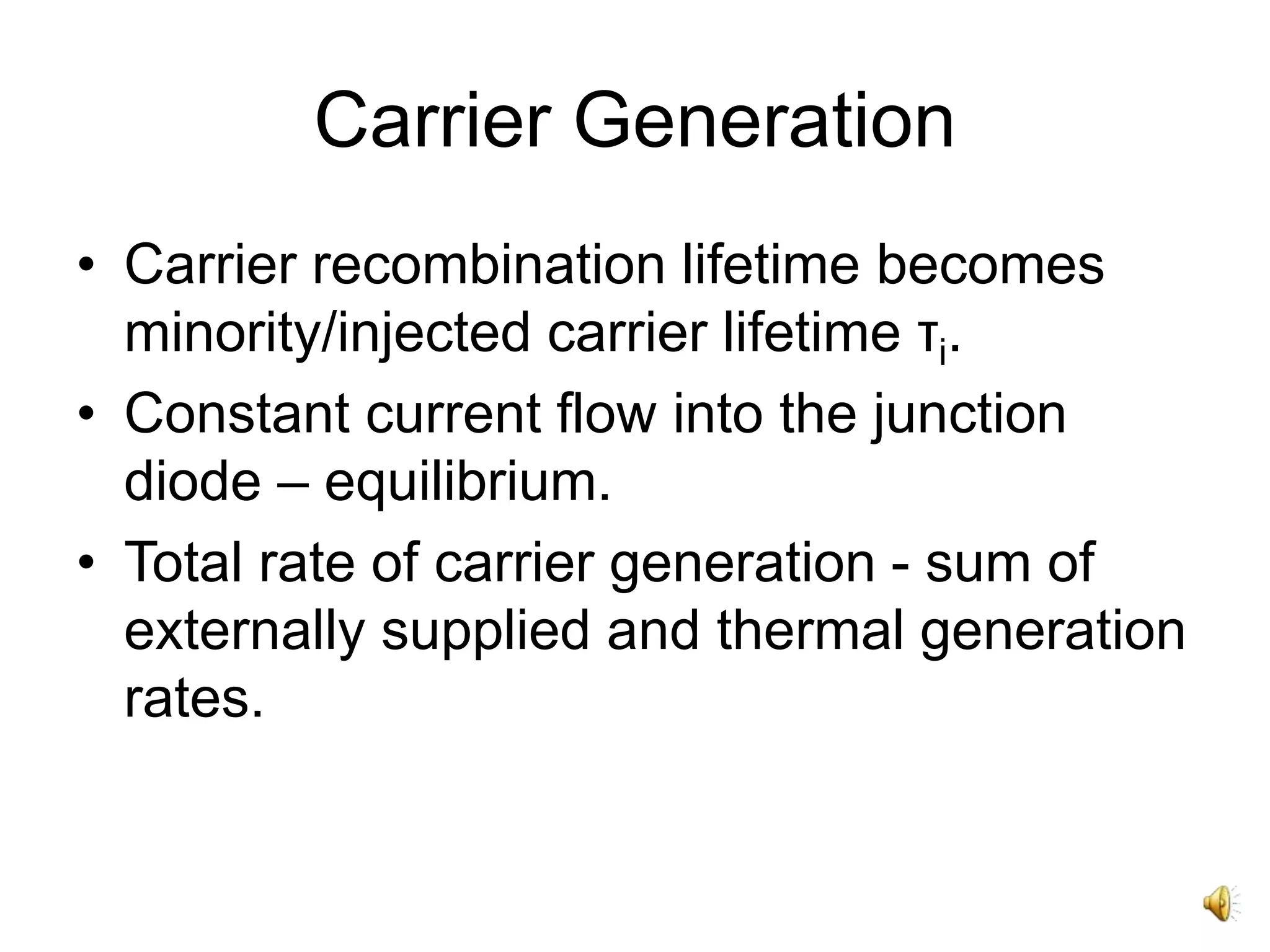
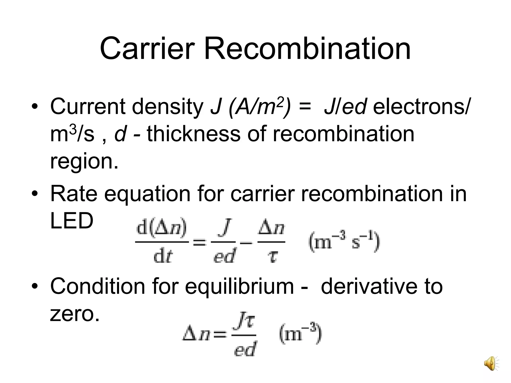
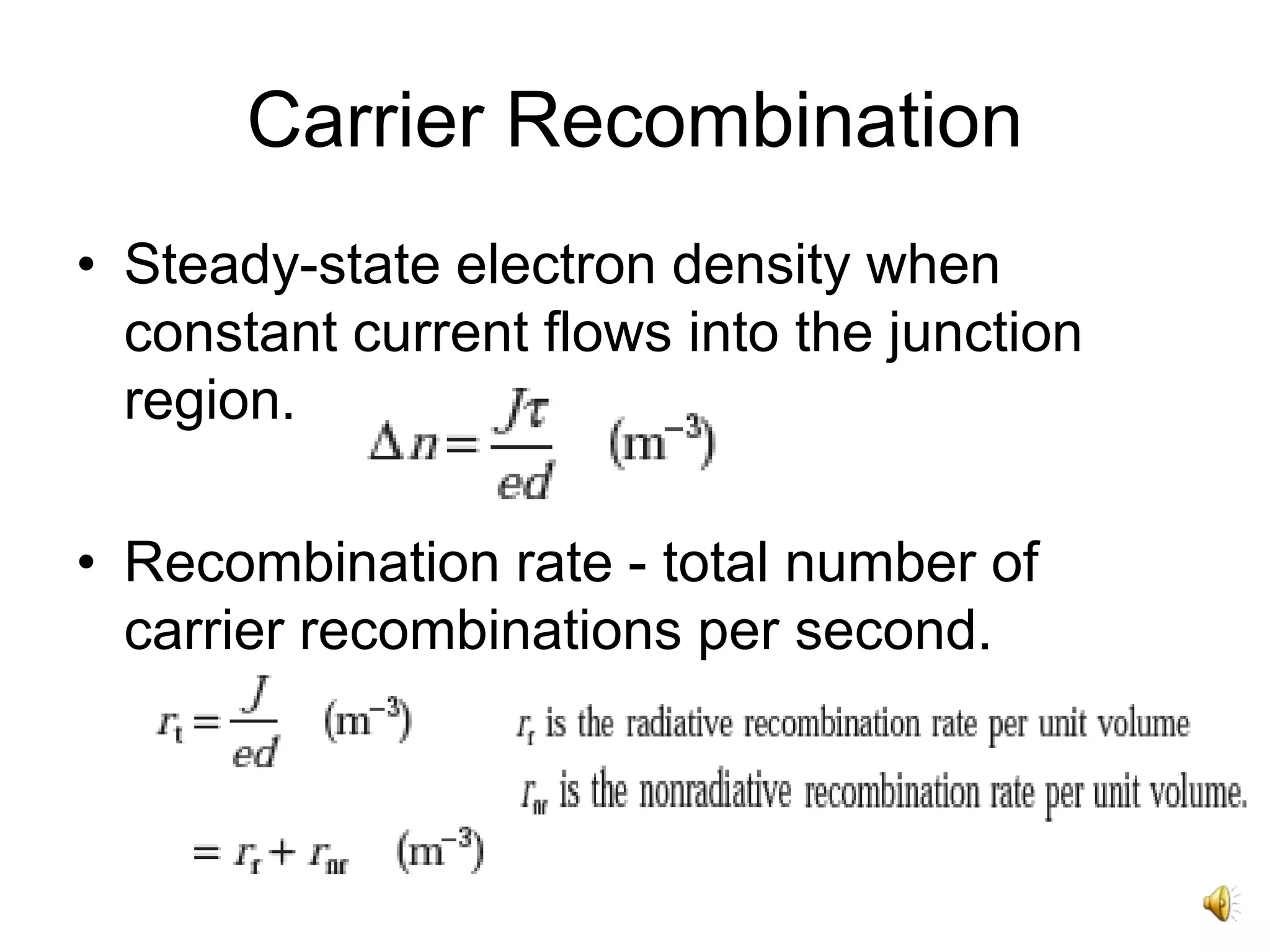
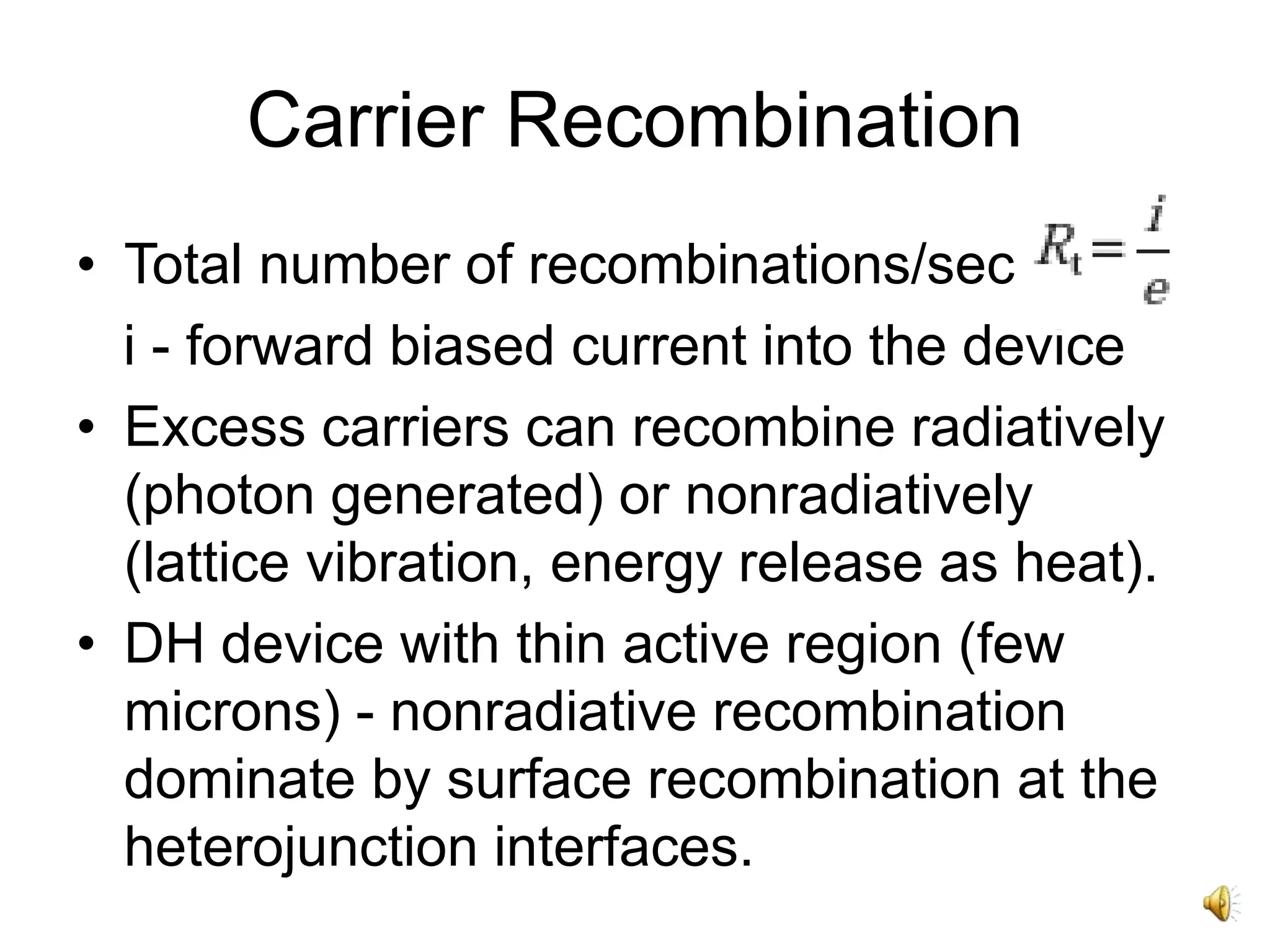
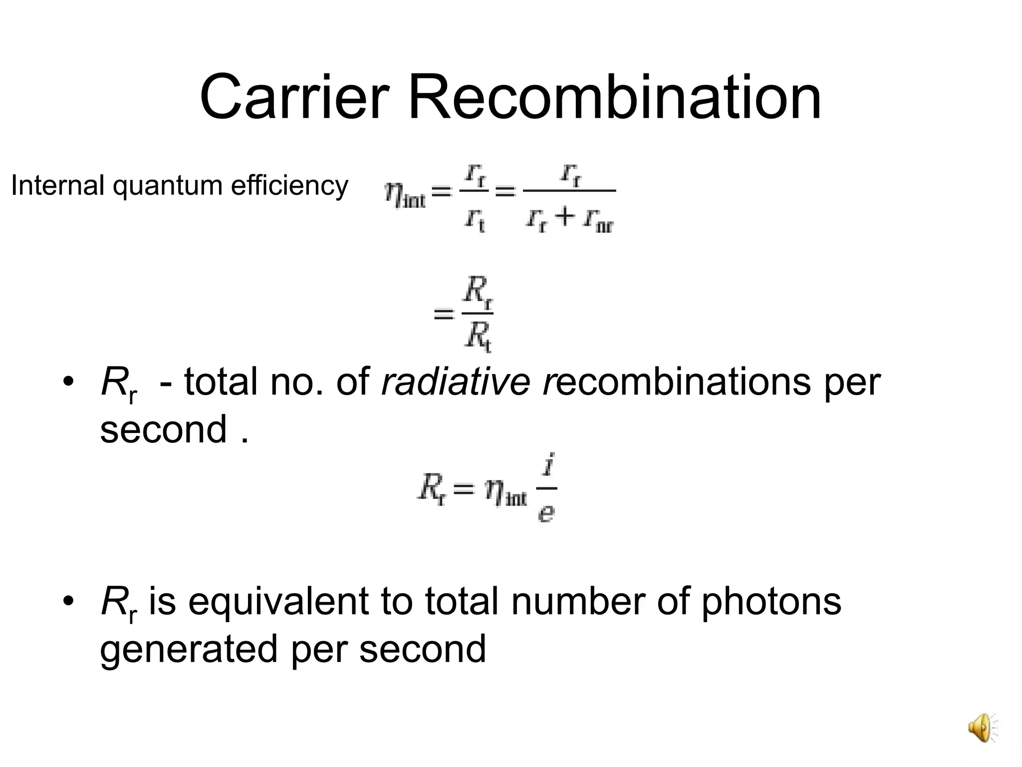
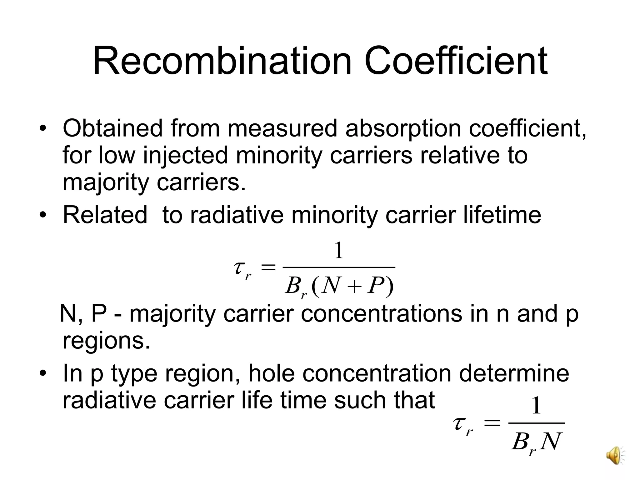
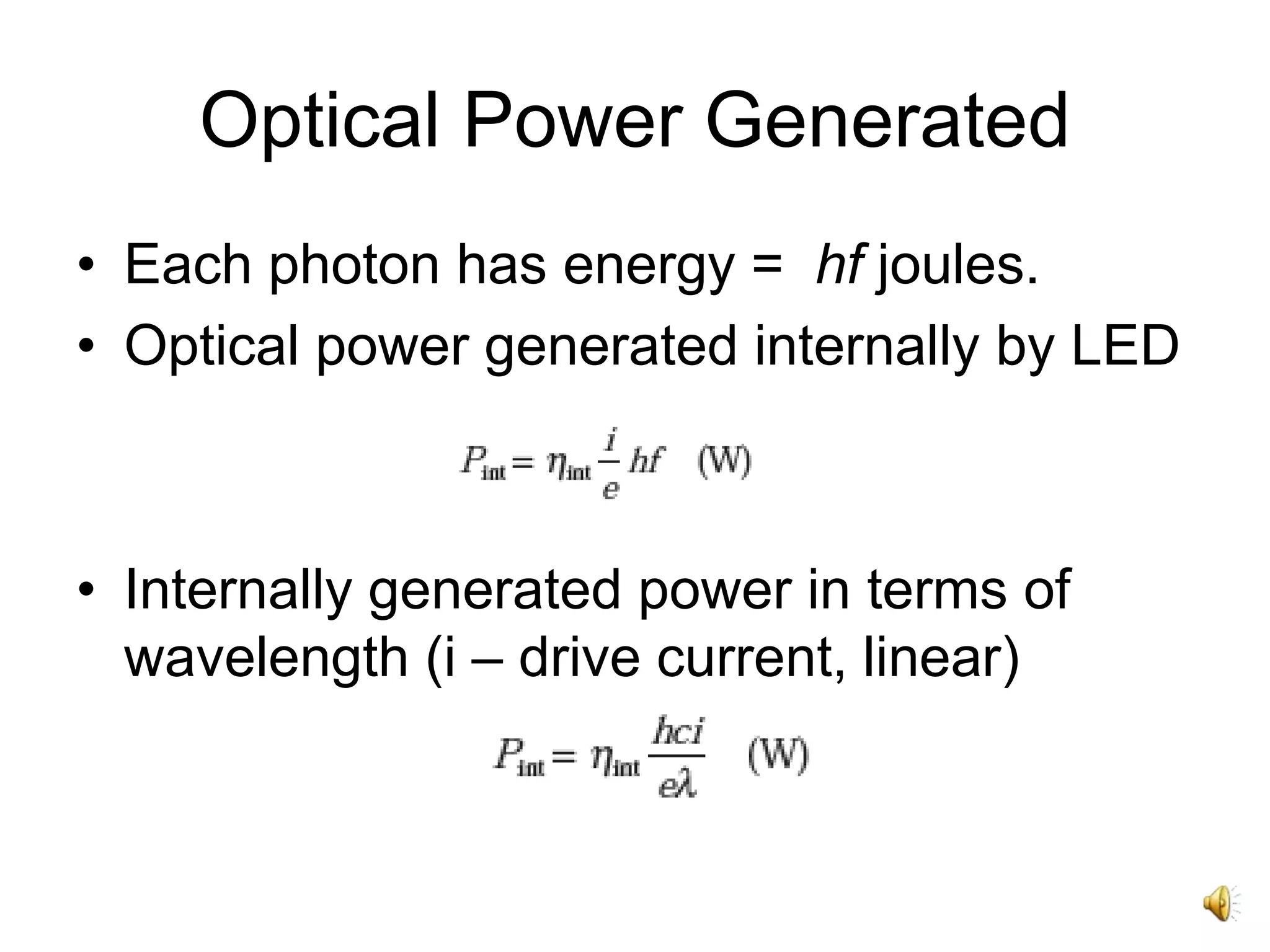
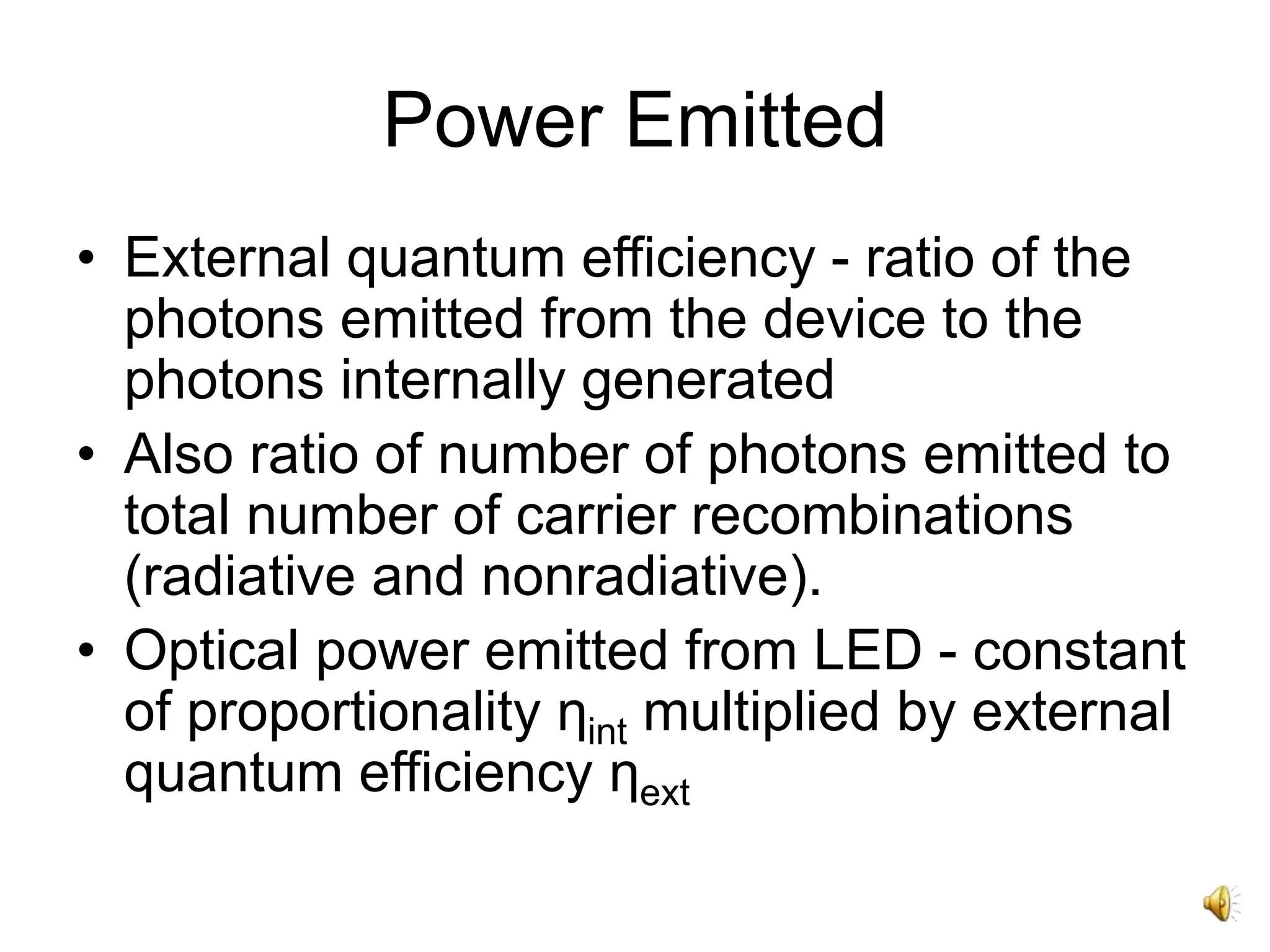
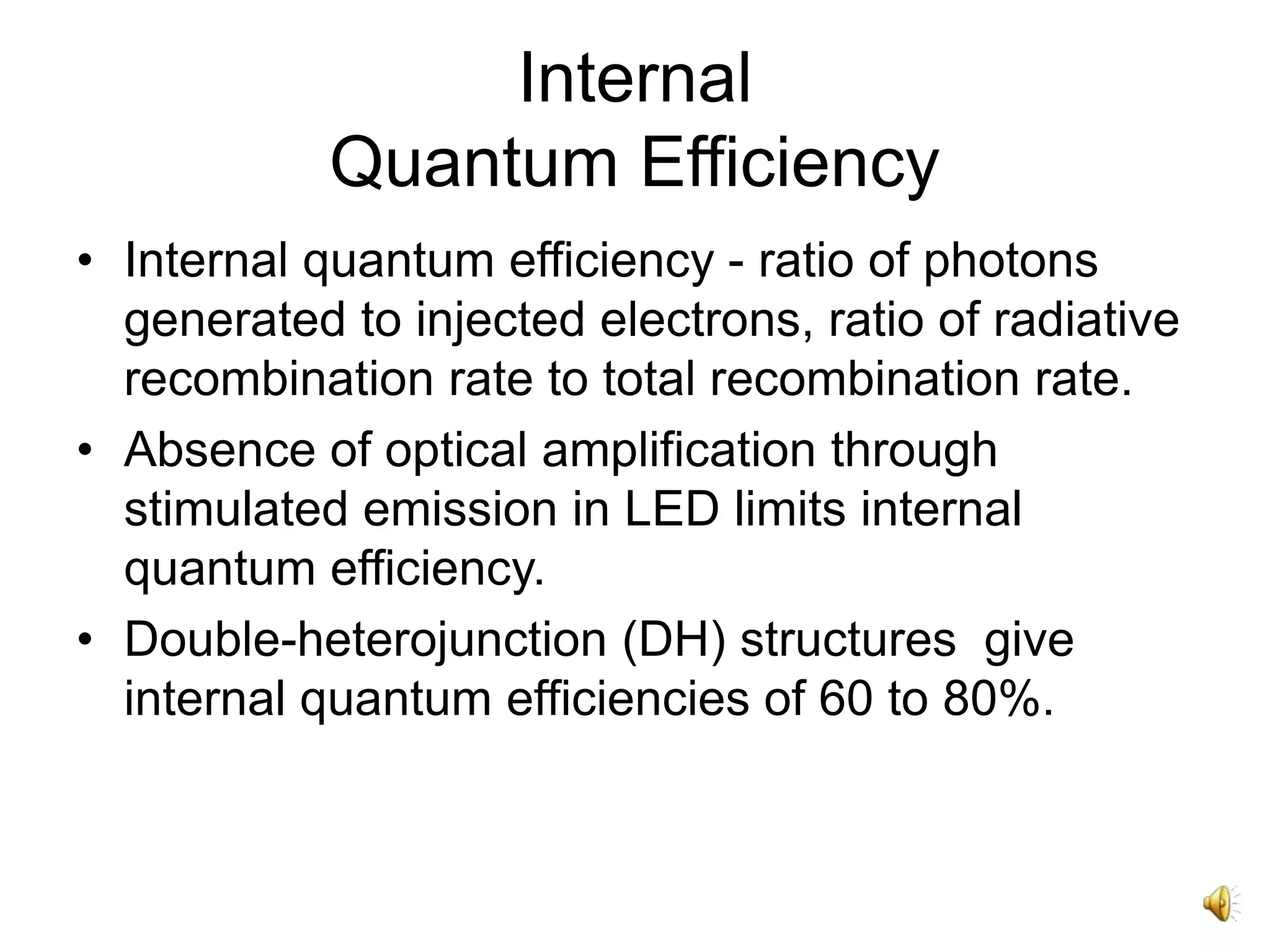
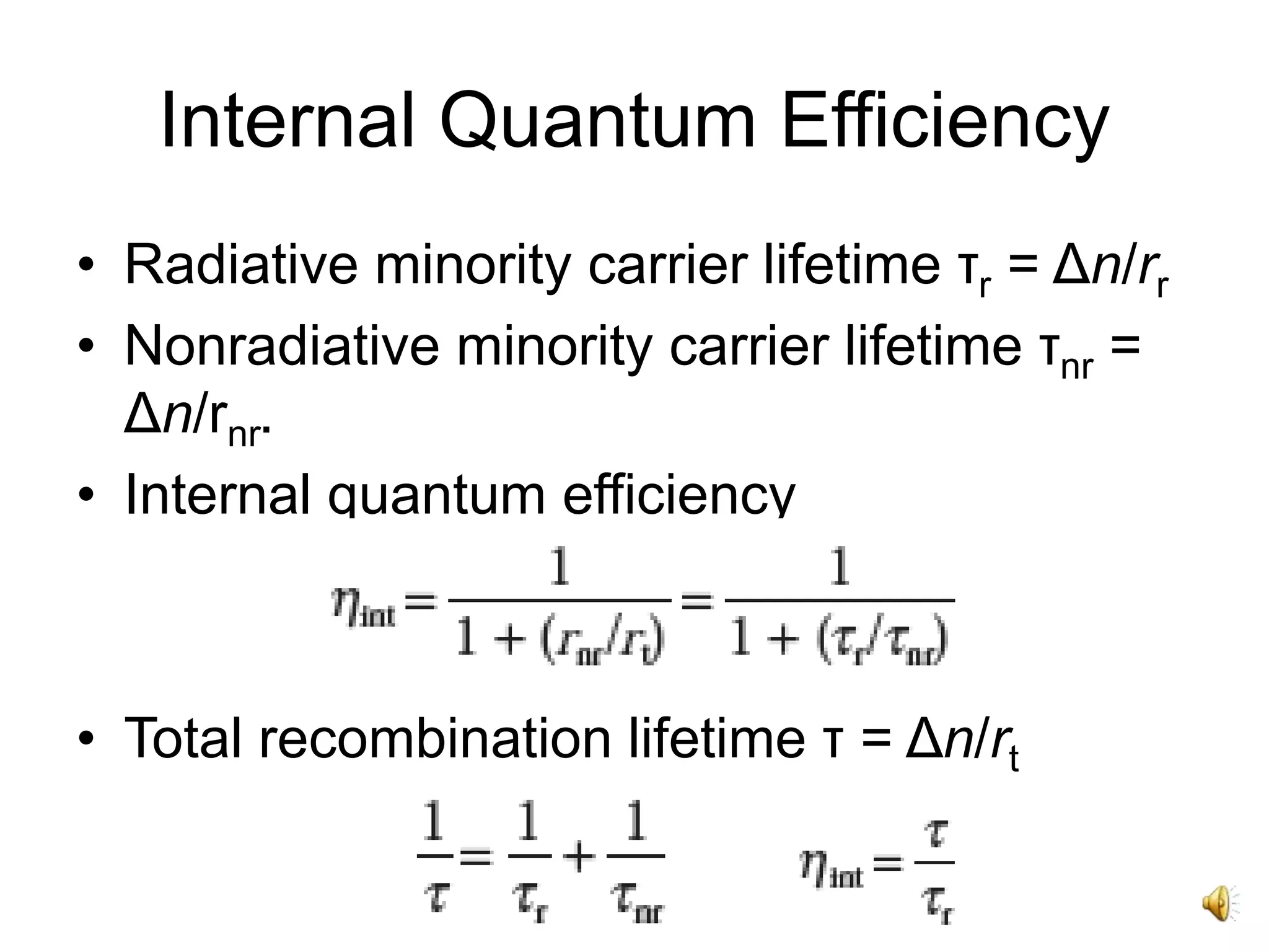
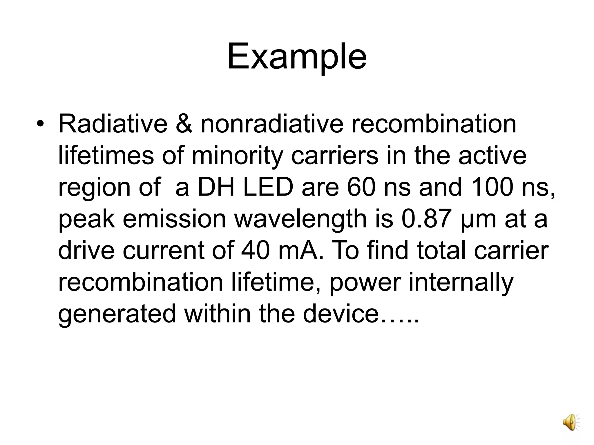
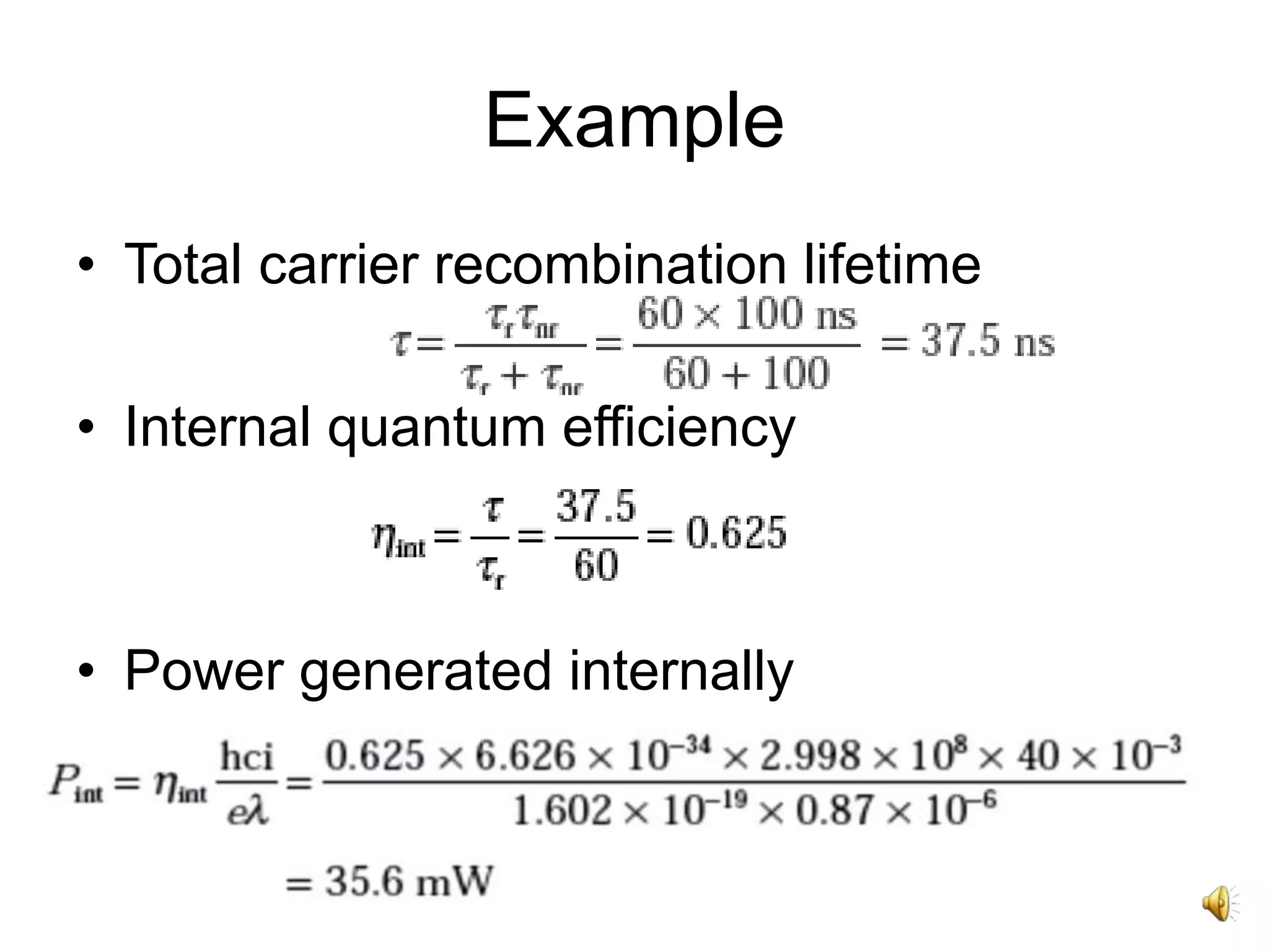
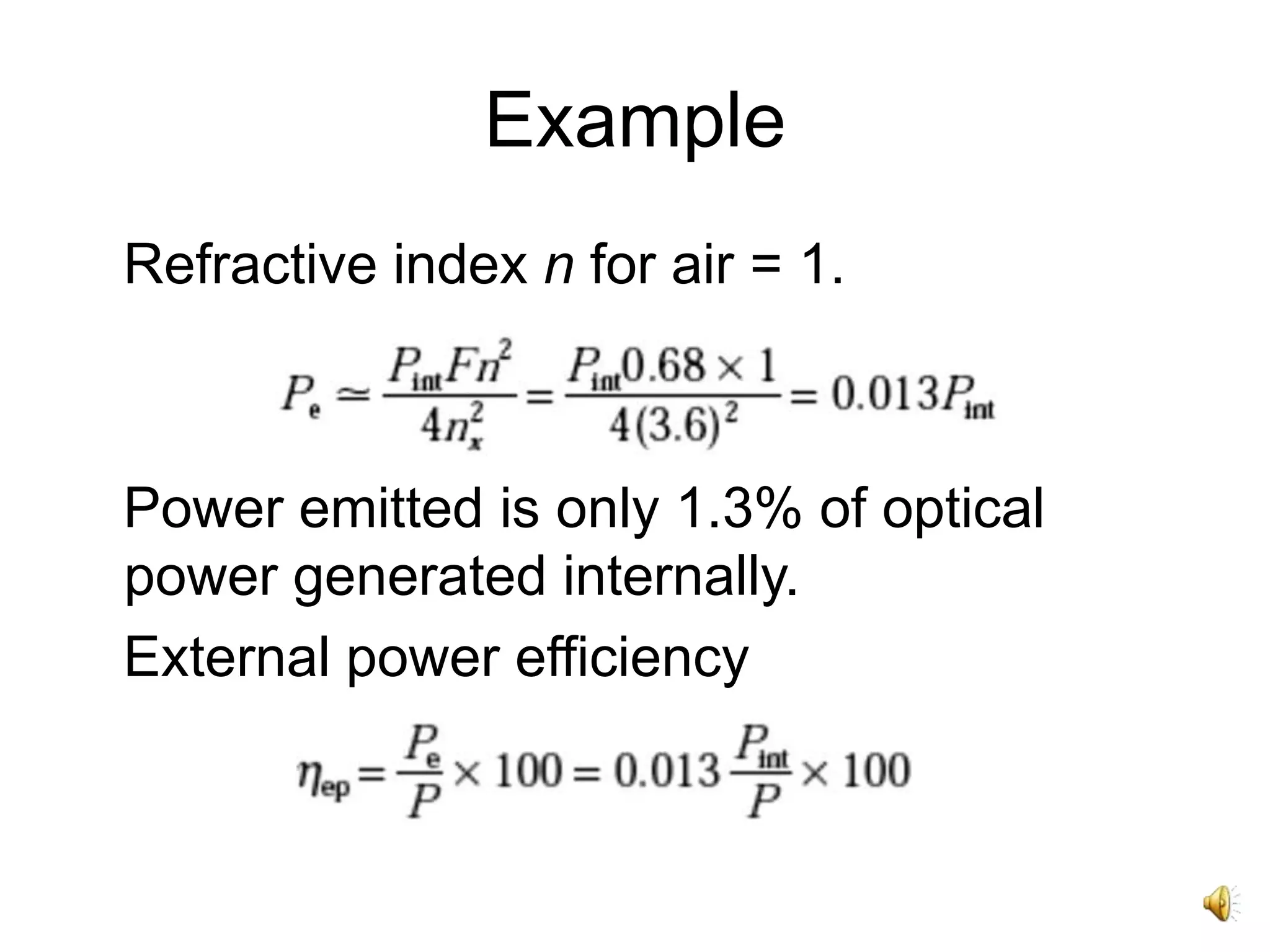
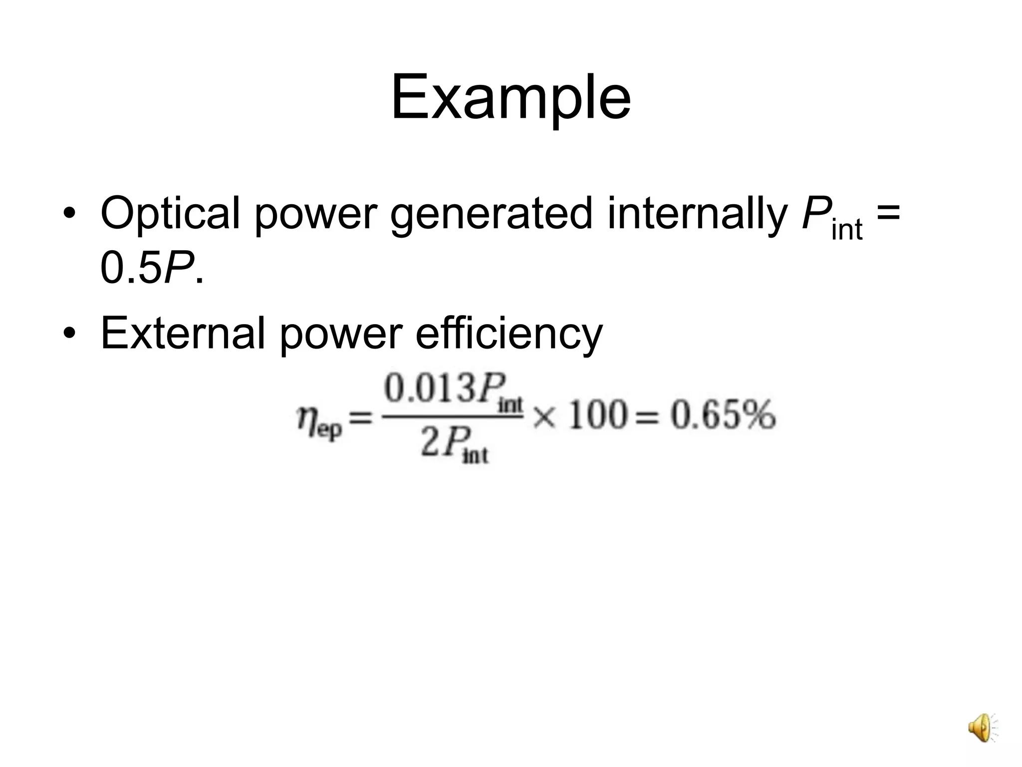
The attached narrated power point presentation offers a mathematical treatment of parameters of an LED such as output power and efficiency. A few worked out examples can also be found.
2. Contents
• Excess Minority Carrier Density
• Carrier Generation.
• Carrier Recombination
• Power Generated.
• Quantum Efficiency.
• Power Efficiency.
• Problems and Solutions.
3. Internal Power Generated
• Power generated internally determined by
considering excess electrons and holes in
p- and n-type material (minority carriers)
when forward biased.
• Charge Neutrality - excess density of
electrons & holes equal, Δn = Δp - injected
carriers created and recombine in pairs.
• Extrinsic materials - one carrier type have
much higher concentration than other.
4. Excess Minority Carrier Density
• In p-type region hole concentration >
electron concentration.
• Excess minority carrier density decays
exponentially with time
Δn(0) - initial injected excess electron
density, τ - total carrier recombination
lifetime.
• Δn is only a small fraction of the majority
carriers, all of minority carriers.
5. Carrier Generation
• Carrier recombination lifetime becomes
minority/injected carrier lifetime τi.
• Constant current flow into the junction
diode – equilibrium.
• Total rate of carrier generation - sum of
externally supplied and thermal generation
rates.
6. Carrier Recombination
• Current density J (A/m2) = J/ed electrons/
m3/s , d - thickness of recombination
region.
• Rate equation for carrier recombination in
LED
• Condition for equilibrium - derivative to
zero.
7. Carrier Recombination
• Steady-state electron density when
constant current flows into the junction
region.
• Recombination rate - total number of
carrier recombinations per second.
8. Carrier Recombination
• Total number of recombinations/sec
i - forward biased current into the device
• Excess carriers can recombine radiatively
(photon generated) or nonradiatively
(lattice vibration, energy release as heat).
• DH device with thin active region (few
microns) - nonradiative recombination
dominate by surface recombination at the
heterojunction interfaces.
9. Carrier Recombination
• Rr - total no. of radiative recombinations per
second .
• Rr is equivalent to total number of photons
generated per second
Internal quantum efficiency
10. Recombination Coefficient
• Obtained from measured absorption coefficient,
for low injected minority carriers relative to
majority carriers.
• Related to radiative minority carrier lifetime
N, P - majority carrier concentrations in n and p
regions.
• In p type region, hole concentration determine
radiative carrier life time such that 1
r
rB N
1
( )
r
rB N P
11. Optical Power Generated
• Each photon has energy = hf joules.
• Optical power generated internally by LED
• Internally generated power in terms of
wavelength (i – drive current, linear)
12. Power Emitted
• External quantum efficiency - ratio of the
photons emitted from the device to the
photons internally generated
• Also ratio of number of photons emitted to
total number of carrier recombinations
(radiative and nonradiative).
• Optical power emitted from LED - constant
of proportionality ηint multiplied by external
quantum efficiency ηext
13. Internal
Quantum Efficiency
• Internal quantum efficiency - ratio of photons
generated to injected electrons, ratio of radiative
recombination rate to total recombination rate.
• Absence of optical amplification through
stimulated emission in LED limits internal
quantum efficiency.
• Double-heterojunction (DH) structures give
internal quantum efficiencies of 60 to 80%.
15. Example
• Radiative & nonradiative recombination
lifetimes of minority carriers in the active
region of a DH LED are 60 ns and 100 ns,
peak emission wavelength is 0.87 μm at a
drive current of 40 mA. To find total carrier
recombination lifetime, power internally
generated within the device…..
16. Example
• Total carrier recombination lifetime
• Internal quantum efficiency
• Power generated internally
17. Example
• LED has an internal quantum efficiency of
62.5% generates 35.6 mW of optical
power, internally. However, this power
level will not be readily emitted from the
device.
18. Radiation Geometry
• Radiation geometry is
Lambertian.
• Surface radiance is
constant in all
directions.
• Maximum intensity
perpendicular to the
planar surface,
reduced on the sides
as per cosine of
viewing angle.
•Coupling Efficiency
19. External Power Efficiency
• Ratio of optical power emitted externally
Pe to electric power provided to device P.
• Optical power emitted Pe into a medium of
low refractive index n from face of planar
LED fabricated from material of refractive
index nx (F - Transmission Factor, Pint -
Power Generated Internally)
20. Example
• Planar LED fabricated from gallium
arsenide has a refractive index of 3.6. To
calculate the optical power emitted into air
as a percentage of internal optical power
for the device when transmission factor at
crystal–air interface is 0.68. When optical
power generated internally is 50% of
electric power supplied, to determine the
external power efficiency…..
21. Example
Refractive index n for air = 1.
Power emitted is only 1.3% of optical
power generated internally.
External power efficiency