Download as PDF, PPTX
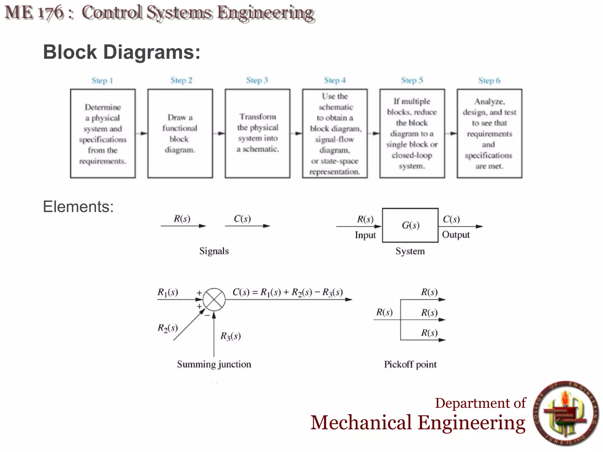
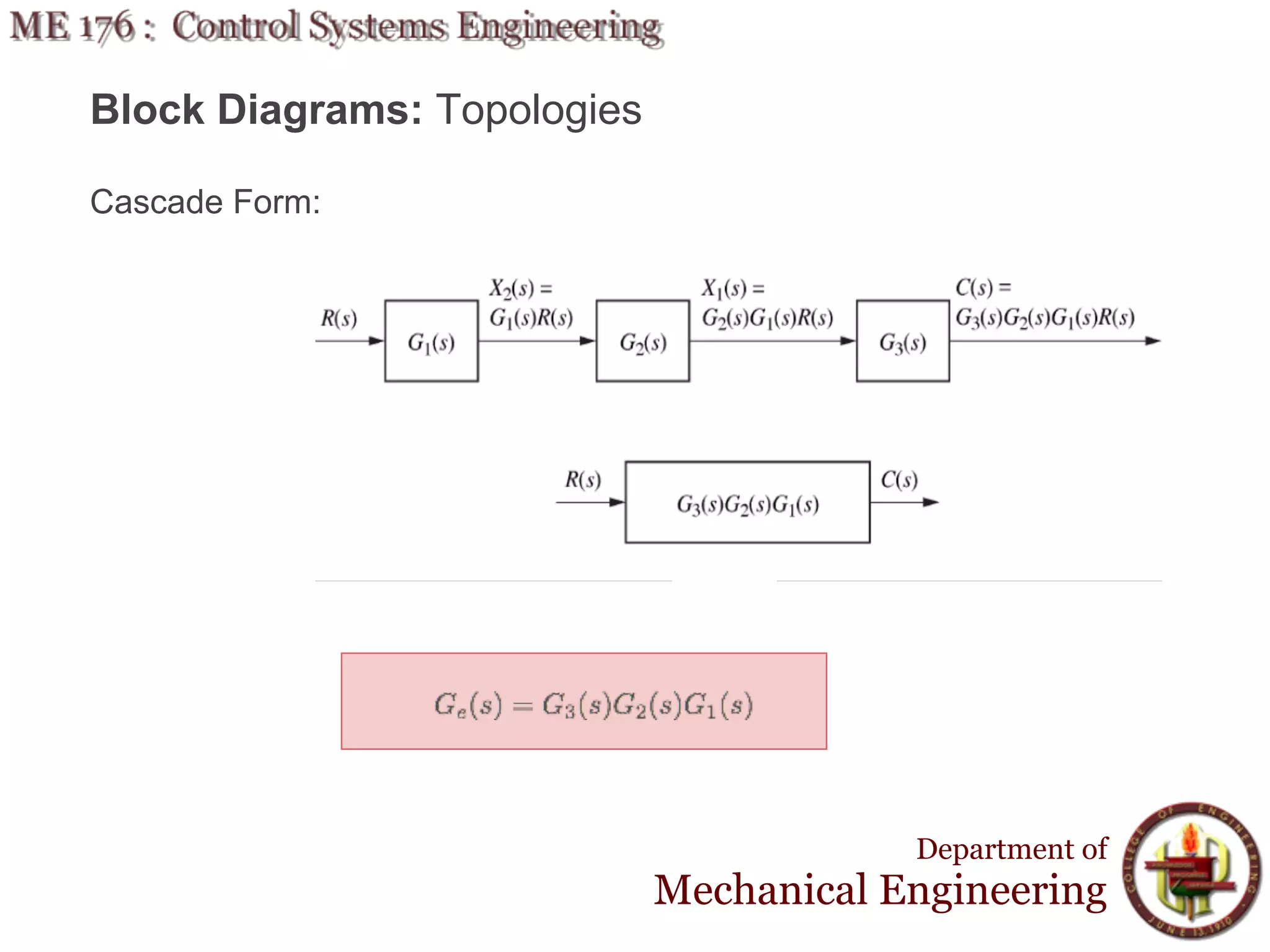
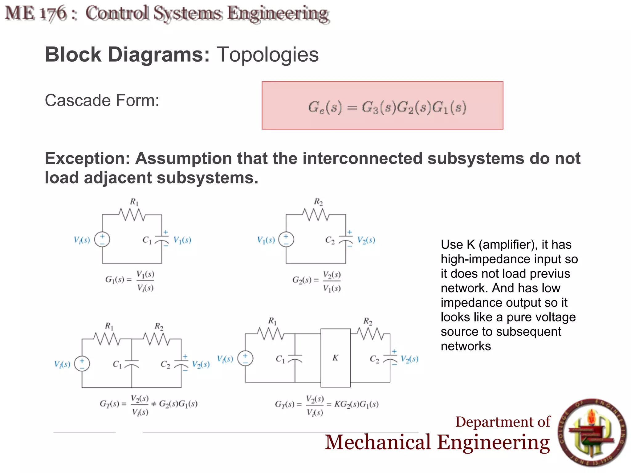
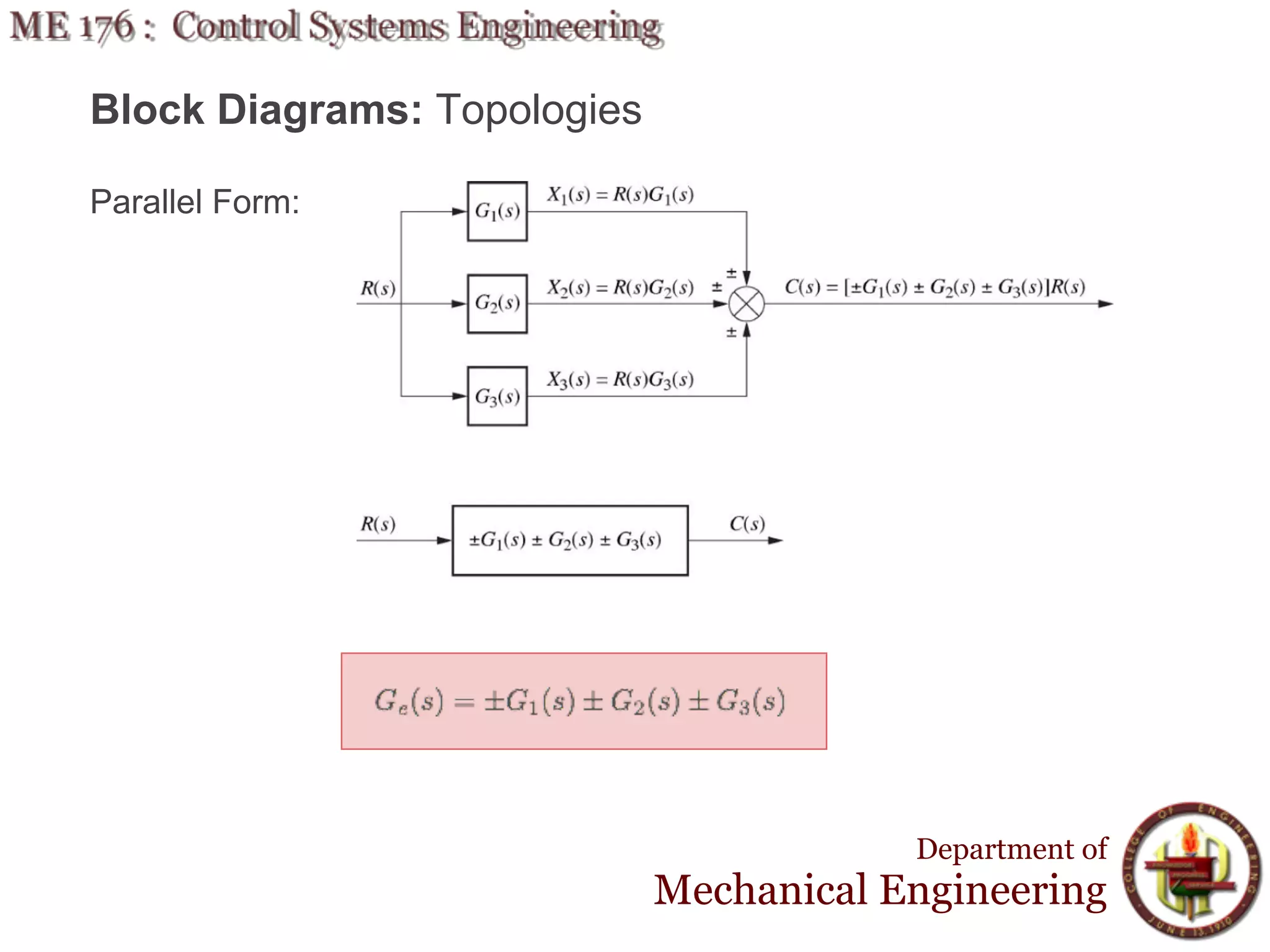
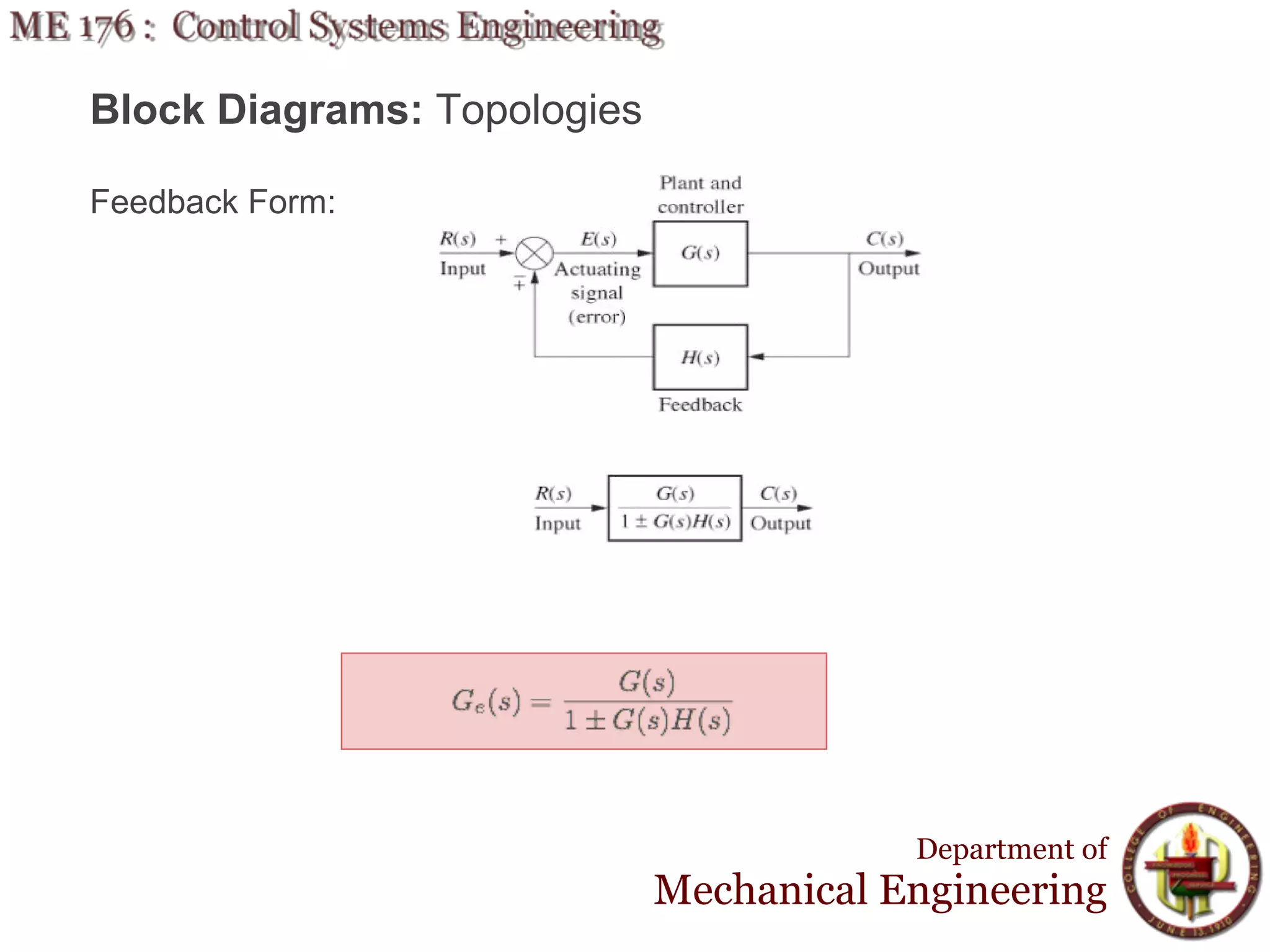
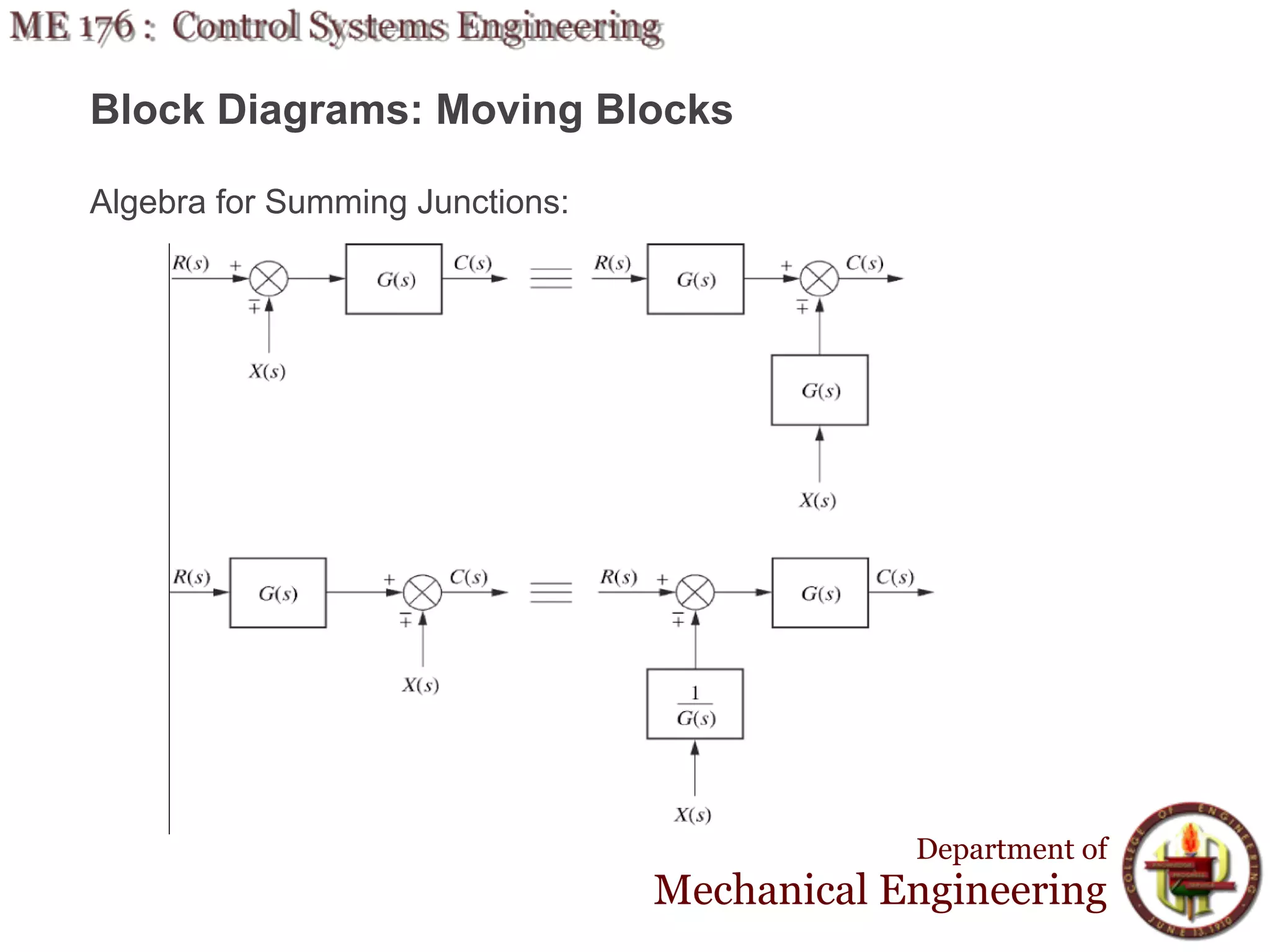
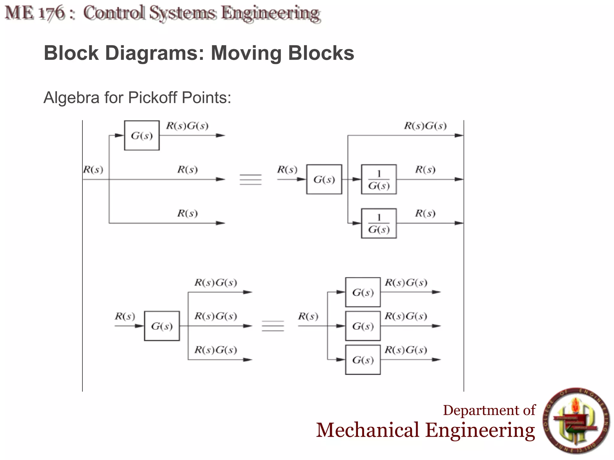
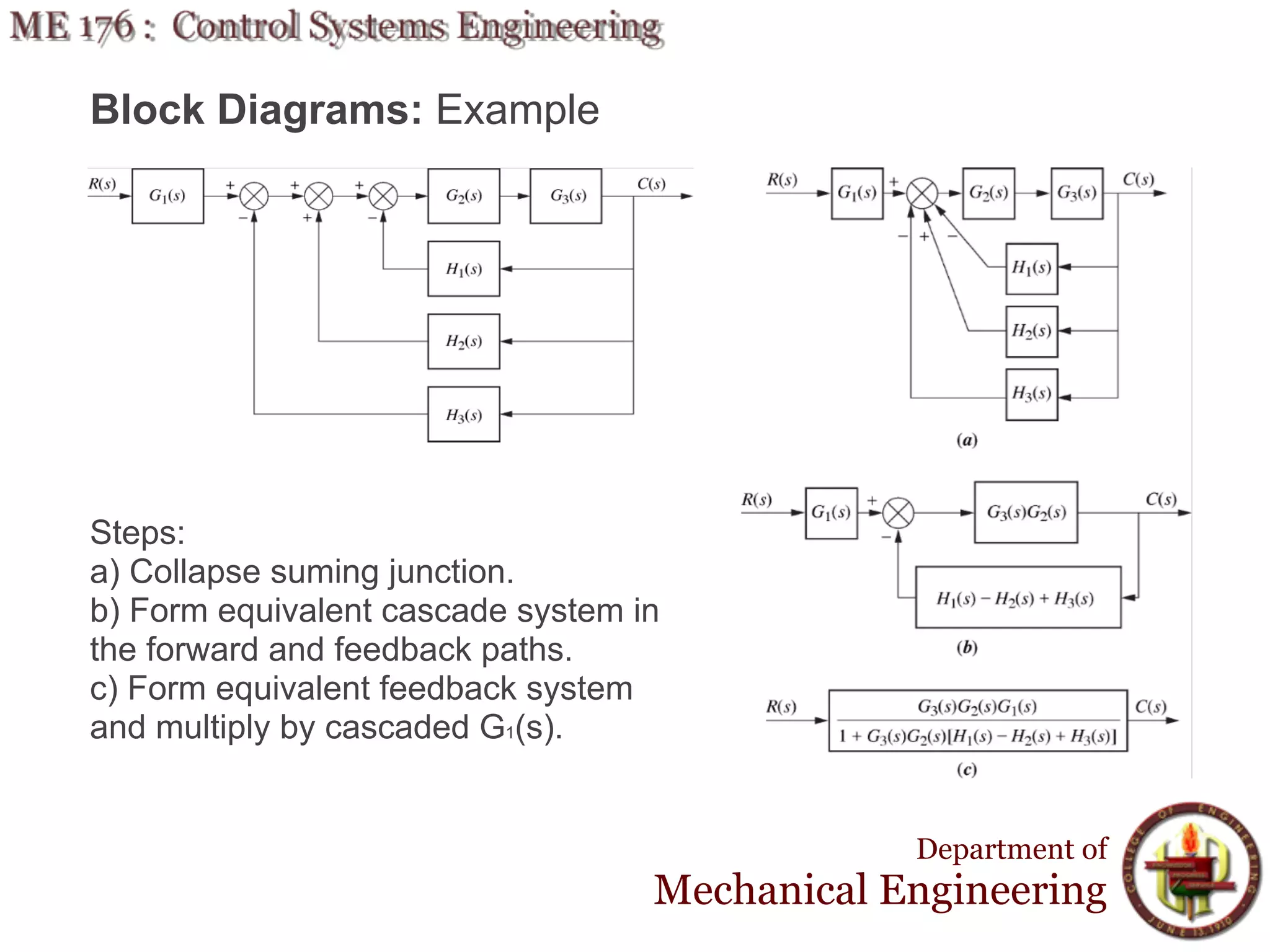
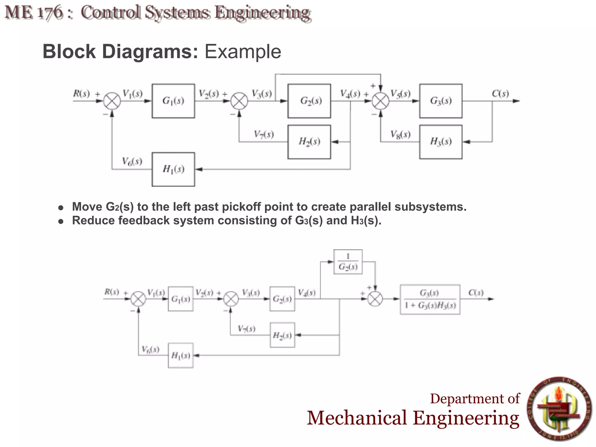
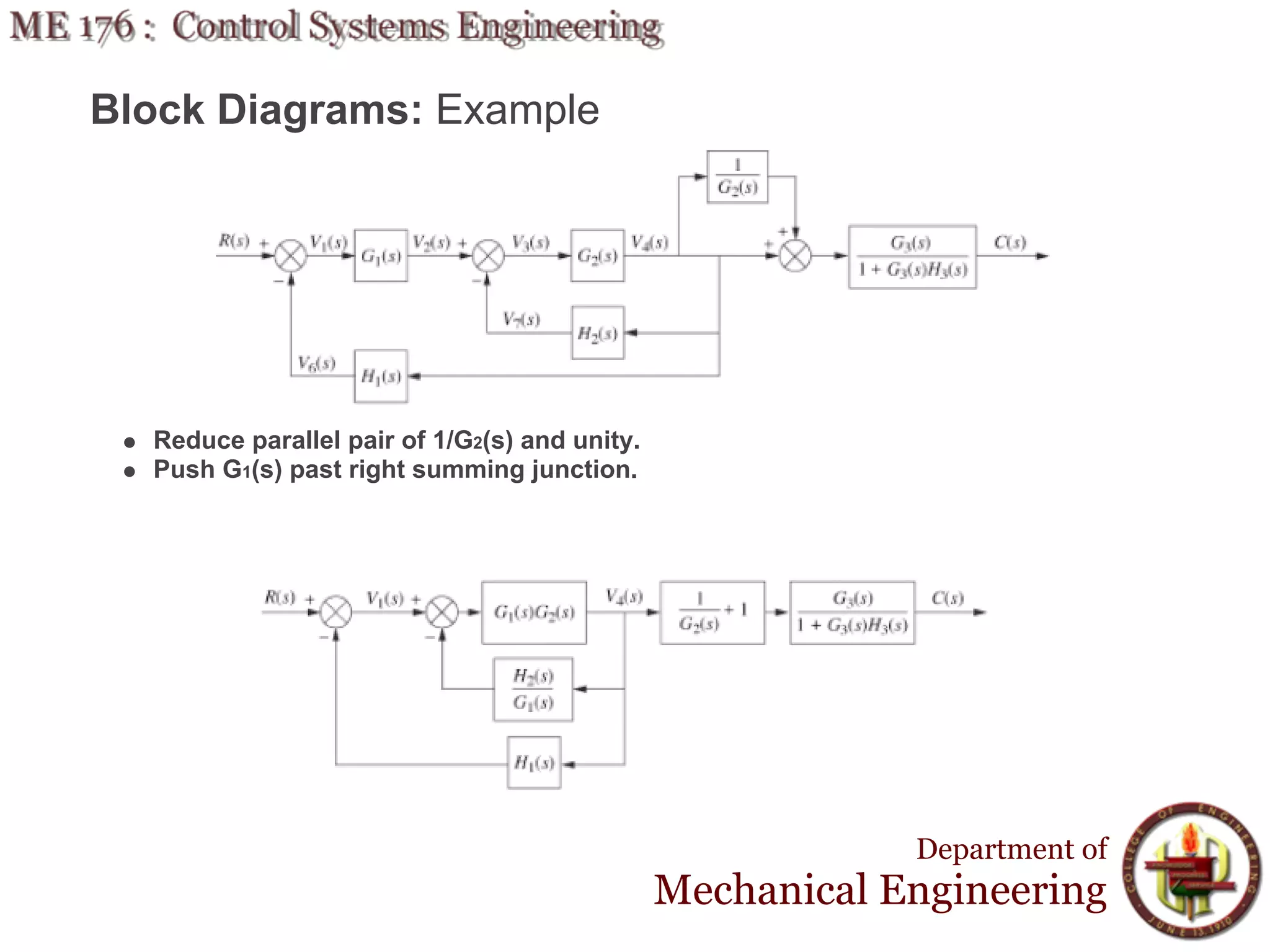
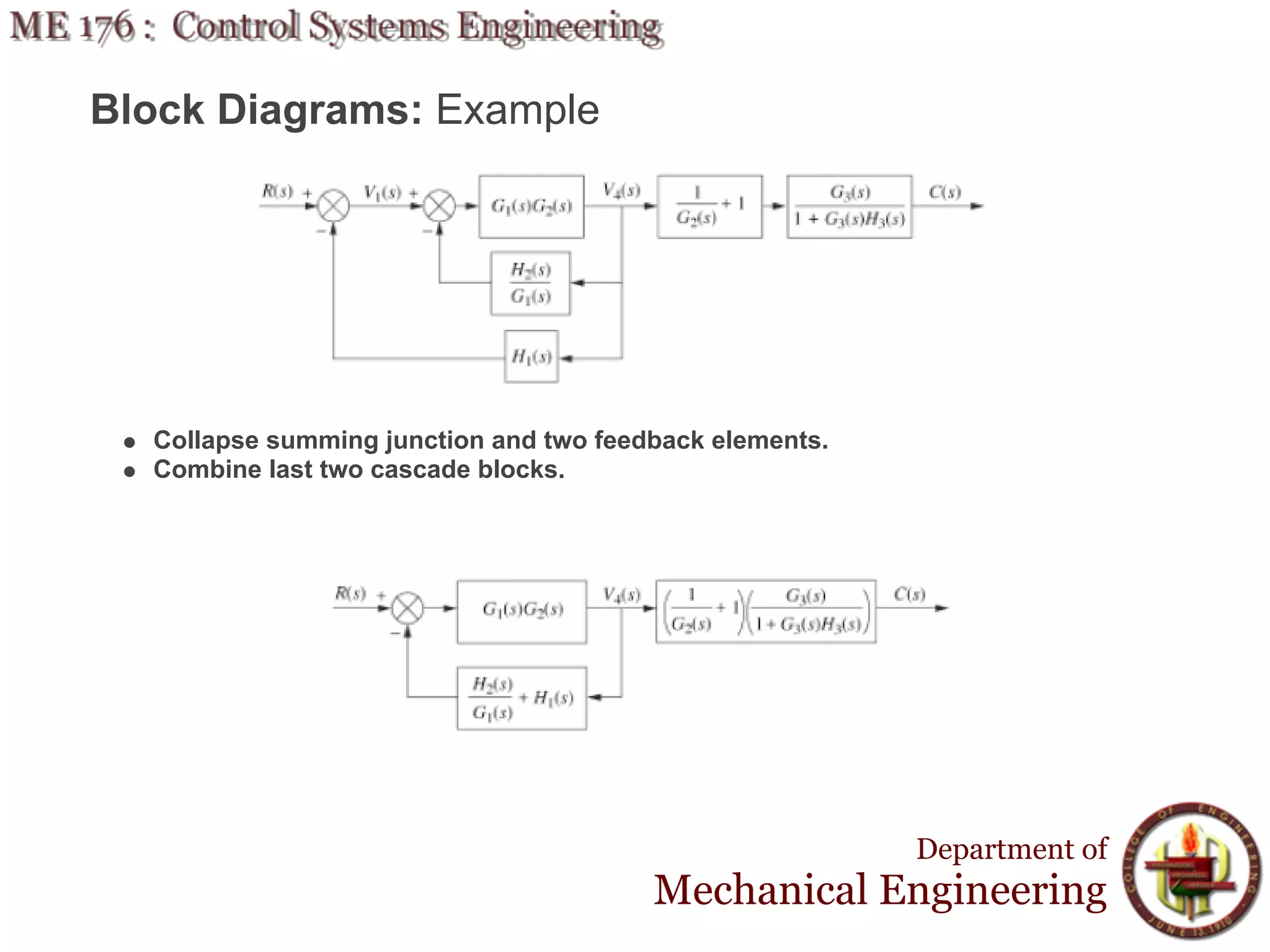
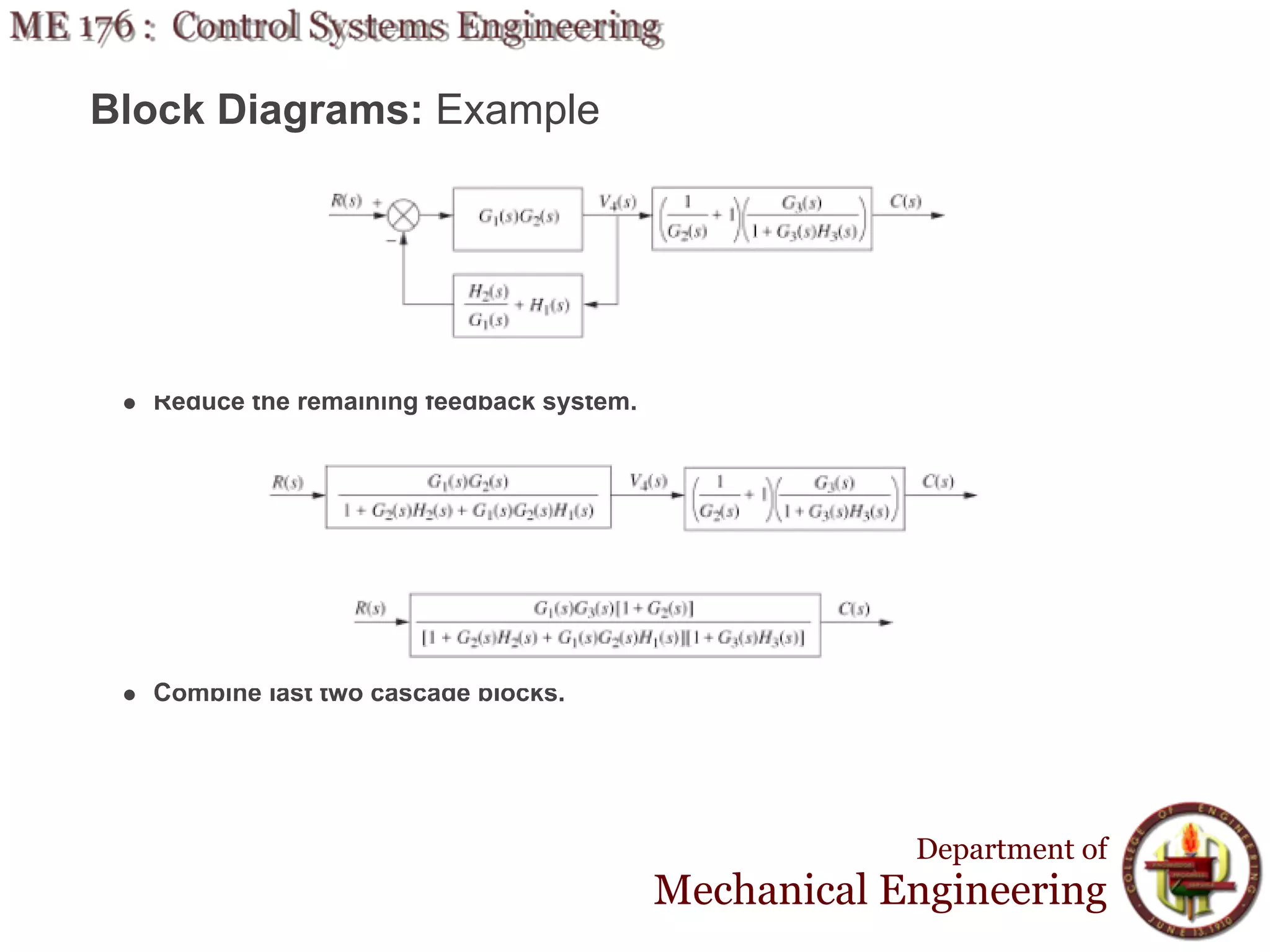

The document discusses control systems engineering and reducing multiple subsystems using block diagrams. It covers block diagram topologies like cascade, parallel, and feedback forms. It shows how to apply algebra to summing junctions and pickoff points when reducing block diagrams. An example problem demonstrates the step-by-step process of reducing a block diagram with multiple feedback loops into an equivalent single-loop feedback system.


![[Ashish tewari] modern_control_design_with_matlab_(book_fi.org)](https://cdn.slidesharecdn.com/ss_thumbnails/ashishtewarimoderncontroldesignwithmatlabbookfi-org-120829235237-phpapp01-thumbnail.jpg?width=640&height=640&fit=bounds)