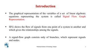
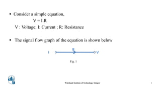
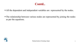
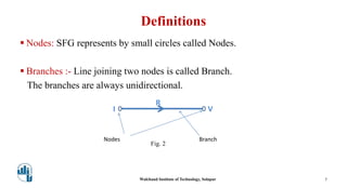
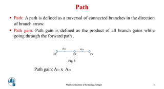
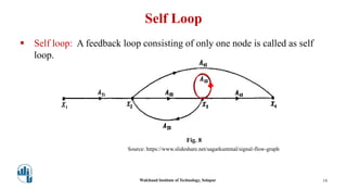
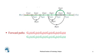
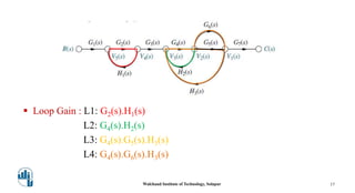
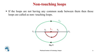
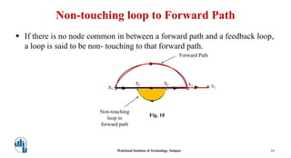
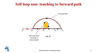
Signal Flow Graph
Ms. Priyanka P. Bidla
(birla.priyanka@gmail.com)
Assistant Professor, Electronics & Telecommunication Engg.
Walchand Institute of Technology, Solapur
(www.witsolapur.org)
Learning Outcome
Students will be able to represent a given physical system into signal
flow graph(SFG).
Walchand Institute of Technology, Solapur 2
At the end of this session,
Contents
 Introduction
 Definitions
 Terminologies
 Examples
Walchand Institute of Technology, Solapur 3
Introduction
 The graphical representation of the variables of a set of linear algebraic
equations representing the system is called Signal Flow Graph
Representation.
 SFG shows the flow of signals from one point of a system to another and
which gives the relationships among the signals.
 A signal-flow graph consists only of branches, which represent signals
and nodes.
Walchand Institute of Technology, Solapur 4
 Consider a simple equation,
V = I.R
V : Voltage; I: Current ; R: Resistance
 The signal flow graph of the equation is shown below
I V
R
Walchand Institute of Technology, Solapur 5
Fig. 1
Contd..
 All the dependent and independent variables are represented by the nodes.
 The relationship between various nodes are represented by joining the nodes
as per the equations.
Walchand Institute of Technology, Solapur 6
Definitions
 Nodes: SFG represents by small circles called Nodes.
 Branches :- Line joining two nodes is called Branch.
The branches are always unidirectional.
Walchand Institute of Technology, Solapur 7
I V
R
BranchNodes
Fig. 2
Terminologies
 Input / Source Node: A node has only outgoing branches is known as
source/input node.
 Output/ Sink Node: A node has only incoming branches is known as
sink/output node.
 Chain Node: A node has incoming and outgoing branches is known as
chain node.
Walchand Institute of Technology, Solapur 8
Path
 Path: A path is defined as a traversal of connected branches in the direction
of branch arrow.
 Path gain: Path gain is defined as the product of all branch gains while
going through the forward path .
Path gain: A12 x A23
Walchand Institute of Technology, Solapur 9
X1 X2 X3
A23A12
Fig. 3
 Dummy nodes: The nodes R and C having branch ‘1’ can be added at input
and output respectively. These nodes are called dummy nodes.
Fig. 4
Source: https://www.slideshare.net/sagarkuntmal/signal-flow-graph
Walchand Institute of Technology, Solapur 10
X1 X2
 Forward Path: A path from the input to the output node is called as forward
path.
P1: G1.G2.G3
P2: G1.G4
Walchand Institute of Technology, Solapur 11
Fig. 5
Loop
 Loop: A closed path from a node to the same node is called loop.
Walchand Institute of Technology, Solapur
Fig. 6
Source: https://bit.ly/2Q1d2LF
12
Loop gain
 Loop gain: The product of all the gains forming a loop.
Walchand Institute of Technology, Solapur
Fig. 7
Source: https://www.slideshare.net/sagarkuntmal/signal-flow-graph
Loop gain = A32 A23
13
Self Loop
 Self loop: A feedback loop consisting of only one node is called as self
loop.
Walchand Institute of Technology, Solapur 14
Fig. 8
Source: https://www.slideshare.net/sagarkuntmal/signal-flow-graph
Think and Write
Consider the signal flow graph below and identify the following
1] Forward paths
2] Loops
3] Loop gain
Walchand Institute of Technology, Solapur 15
 Forward paths: G1(s).G2(s).G3(s).G4(s).G5(s).G7(s)
G1(s).G2(s).G3(s).G4(s).G6(s).G7(s)
Walchand Institute of Technology, Solapur 16
 Loop Gain : L1: G2(s).H1(s)
L2: G4(s).H2(s)
L3: G4(s).G5(s).H3(s)
L4: G4(s).G6(s).H3(s)
Walchand Institute of Technology, Solapur 17
Non-touching loops
 If the loops are not having any common node between them then those
loops are called as non- touching loops.
Walchand Institute of Technology, Solapur 18
X1
L2
Fig. 9
L1
X4
X3X2
Non-touching loop to Forward Path
 If there is no node common in between a forward path and a feedback loop,
a loop is said to be non- touching to that forward path.
X5
X4
Forward Path
Non-touching
loop to
forward path
Walchand Institute of Technology, Solapur 19
Fig. 10
Self loop non- touching to forward path
Walchand Institute of Technology, Solapur 20
X1
Fig. 11
X4X3X2 X5
Forward Path
Self loop Non-
touching to
forward path
References
1] Control Systems Engineering I. J. Nagrath & M Gopal New Age
International Publication(5th Edition)
2] https://www.slideshare.net/sagarkuntmal/signal-flow-graph
3] https://image.slidesharecdn.com/signalflowgraphexamples-150415045856-
conversion-gate01/95/signal-flow-graph-9-638.jpg?cb=1451886608
21Walchand Institute of Technology, Solapur
Thank you
Walchand Institute of Technology, Solapur 22

Signal Flow Graph Introduction

  • 1.
    Signal Flow Graph Ms.Priyanka P. Bidla (birla.priyanka@gmail.com) Assistant Professor, Electronics & Telecommunication Engg. Walchand Institute of Technology, Solapur (www.witsolapur.org)
  • 2.
    Learning Outcome Students willbe able to represent a given physical system into signal flow graph(SFG). Walchand Institute of Technology, Solapur 2 At the end of this session,
  • 3.
    Contents  Introduction  Definitions Terminologies  Examples Walchand Institute of Technology, Solapur 3
  • 4.
    Introduction  The graphicalrepresentation of the variables of a set of linear algebraic equations representing the system is called Signal Flow Graph Representation.  SFG shows the flow of signals from one point of a system to another and which gives the relationships among the signals.  A signal-flow graph consists only of branches, which represent signals and nodes. Walchand Institute of Technology, Solapur 4
  • 5.
     Consider asimple equation, V = I.R V : Voltage; I: Current ; R: Resistance  The signal flow graph of the equation is shown below I V R Walchand Institute of Technology, Solapur 5 Fig. 1
  • 6.
    Contd..  All thedependent and independent variables are represented by the nodes.  The relationship between various nodes are represented by joining the nodes as per the equations. Walchand Institute of Technology, Solapur 6
  • 7.
    Definitions  Nodes: SFGrepresents by small circles called Nodes.  Branches :- Line joining two nodes is called Branch. The branches are always unidirectional. Walchand Institute of Technology, Solapur 7 I V R BranchNodes Fig. 2
  • 8.
    Terminologies  Input /Source Node: A node has only outgoing branches is known as source/input node.  Output/ Sink Node: A node has only incoming branches is known as sink/output node.  Chain Node: A node has incoming and outgoing branches is known as chain node. Walchand Institute of Technology, Solapur 8
  • 9.
    Path  Path: Apath is defined as a traversal of connected branches in the direction of branch arrow.  Path gain: Path gain is defined as the product of all branch gains while going through the forward path . Path gain: A12 x A23 Walchand Institute of Technology, Solapur 9 X1 X2 X3 A23A12 Fig. 3
  • 10.
     Dummy nodes:The nodes R and C having branch ‘1’ can be added at input and output respectively. These nodes are called dummy nodes. Fig. 4 Source: https://www.slideshare.net/sagarkuntmal/signal-flow-graph Walchand Institute of Technology, Solapur 10 X1 X2
  • 11.
     Forward Path:A path from the input to the output node is called as forward path. P1: G1.G2.G3 P2: G1.G4 Walchand Institute of Technology, Solapur 11 Fig. 5
  • 12.
    Loop  Loop: Aclosed path from a node to the same node is called loop. Walchand Institute of Technology, Solapur Fig. 6 Source: https://bit.ly/2Q1d2LF 12
  • 13.
    Loop gain  Loopgain: The product of all the gains forming a loop. Walchand Institute of Technology, Solapur Fig. 7 Source: https://www.slideshare.net/sagarkuntmal/signal-flow-graph Loop gain = A32 A23 13
  • 14.
    Self Loop  Selfloop: A feedback loop consisting of only one node is called as self loop. Walchand Institute of Technology, Solapur 14 Fig. 8 Source: https://www.slideshare.net/sagarkuntmal/signal-flow-graph
  • 15.
    Think and Write Considerthe signal flow graph below and identify the following 1] Forward paths 2] Loops 3] Loop gain Walchand Institute of Technology, Solapur 15
  • 16.
     Forward paths:G1(s).G2(s).G3(s).G4(s).G5(s).G7(s) G1(s).G2(s).G3(s).G4(s).G6(s).G7(s) Walchand Institute of Technology, Solapur 16
  • 17.
     Loop Gain: L1: G2(s).H1(s) L2: G4(s).H2(s) L3: G4(s).G5(s).H3(s) L4: G4(s).G6(s).H3(s) Walchand Institute of Technology, Solapur 17
  • 18.
    Non-touching loops  Ifthe loops are not having any common node between them then those loops are called as non- touching loops. Walchand Institute of Technology, Solapur 18 X1 L2 Fig. 9 L1 X4 X3X2
  • 19.
    Non-touching loop toForward Path  If there is no node common in between a forward path and a feedback loop, a loop is said to be non- touching to that forward path. X5 X4 Forward Path Non-touching loop to forward path Walchand Institute of Technology, Solapur 19 Fig. 10
  • 20.
    Self loop non-touching to forward path Walchand Institute of Technology, Solapur 20 X1 Fig. 11 X4X3X2 X5 Forward Path Self loop Non- touching to forward path
  • 21.
    References 1] Control SystemsEngineering I. J. Nagrath & M Gopal New Age International Publication(5th Edition) 2] https://www.slideshare.net/sagarkuntmal/signal-flow-graph 3] https://image.slidesharecdn.com/signalflowgraphexamples-150415045856- conversion-gate01/95/signal-flow-graph-9-638.jpg?cb=1451886608 21Walchand Institute of Technology, Solapur
  • 22.
    Thank you Walchand Instituteof Technology, Solapur 22