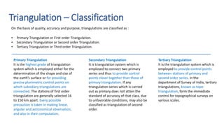
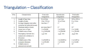
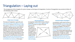
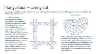
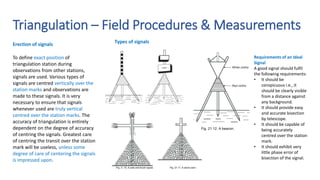
This presentation constitutes an integral component of a designated course curriculum and is crafted and disseminated for its intended audience. None of the contents within this presentation should be construed as a formal publication on the subject matter. The author has extensively referenced published resources in the preparation of this presentation, and proper citations will be provided in the bibliography upon completion of its development.
2. Triangulation – An Introduction
Triangulation is one of the methods of fixing accurate controls. It is process of
measuring the angles of a chain or a network or triangles formed by stations
marked on the surface of the earth.
where a, b, and c are the lengths of
the sides of a triangle, and α, β, and γ
are the opposite angles, while R is the
radius of the triangle's circumcircle.
A triangulation system consists of a series of joined or overlapping triangles in which
an occasional side called as base line, is measured and remaining sides are calculated
from the angles measured at the vertices of the triangles, vertices being the control
points are called as triangulation stations.
It is based on the trigonometric proposition that if one side and two angles of a
triangle are known, the remaining sides can be computed.
The method of surveying by triangulation was first introduced by the Dutchmen
Snell in 1615.
3. Triangulation – An Introduction
The side of the first triangle, whose length is predetermined is called the base line
and vertices of the individual triangles are known as triangulation stations.
To minimize accumulation of errors in lengths, subsidiary
bases at suitable intervals are provided and to control
error in azimuth of stations, astronomical observation are
made at intermediate stations.
The triangulation stations at which
astronomical observations for azimuth
are made, are called Laplace stations.
4. Triangulation – Purpose and Objectives
The purpose of triangulation surveys
The main objective of triangulation surveys is to provide a number of stations whose relative and absolute positions, horizontal as
well as vertical, are accurately established. More detailed location or engineering survey is then carried out from these stations.
To determine accurate locations of points in engineering works such as :
• Fixing centre line and abutments of long bridges over large rivers.
• Fixing centre line, terminal points, and shafts for long tunnels.
• Transferring the control points across wide sea channels, large water bodies, etc.
• Detection of crustal movements, etc.
• Finding the direction of the movement of clouds.
To establish accurate control for
plane and geodetic surveys of large
areas, by terrestrial methods.
To establish accurate control for
photogrammetric surveys of large
areas,
To assist in the determination of
the size and shape of the earth by
making observations for latitude,
longitude and gravity.
5. Triangulation – Classification
• Primary Triangulation or First order Triangulation.
• Secondary Triangulation or Second order Triangulation.
• Tertiary Triangulation or Third order Triangulation.
Secondary Triangulation
It is triangulation system which is
employed to connect two primary
series and thus to provide control
points closer together than those of
primary triangulation. If any
triangulation series which is carried
out as primary does not attain the
standard of accuracy of that class, due
to unfavorable conditions, may also be
classified as triangulation of second
order.
Tertiary Triangulation
It is the triangulation system which is
employed to provide control points
between stations of primary and
second order series. In the
department of Survey of India, tertiary
triangulations, known as topo
triangulation, form the immediate
control for topographical surveys on
various scales.
On the basis of quality, accuracy and purpose, triangulations are classified as :
Primary Triangulation
It is the highest grade of triangulation
system which is employed either for the
determination of the shape and size of
the earth’s surface or for providing
precise planimetric control points on
which subsidiary triangulations are
connected. The stations of first order
triangulation are generally selected 16
to 150 km apart. Every possible
precaution is taken in making linear,
angular and astronomical observation,
and also in their computation.
7. Triangulation – Laying out
The arrangement of the triangles of a series is known as the layout of triangulation. A series of triangulation may consists of either of
the following orders shown.
This layout of triangulation is generally used
when control points are provided in a narrow
strip of terrain such as a valley between ridges.
This system is rapid and economical due to its
simplicity of sighting only four other stations,
and does not involve observations of long
diagonals. On the other hand, simple triangles
of a triangulation system do not provide any
check on the accuracy of observations as there
is only one route through which distances can
be computed. To avoid excessive accumulated
errors, check base lines and astronomical
observations for azimuth at frequent intervals
are therefore very necessary, in this layout.
A triangulation system which consists of figures
containing four corner stations and observed
diagonals is known as a layout of braced
quadrilaterals.
This system is
treated to be the
best arrangement
of triangles as it
provides a means
of computing the
lengths of sides
using different
combination of
sides and angles.
Simple chain of triangles Braced quadrilateral
A triangulation system which consists of
figures containing centered polygons and
centered triangles is known as centered
triangles and polygons. This layout of
triangulation is generally used when vast
area in all dimensions is required to be
covered. The centered figures generally are
quadrilaterals, pentagons or hexagons with
central stations. Though this system
provides proper check on the accuracy of
the work, the progress of the work is
generally low due to the fact that more
settings of the instrument are required.
Centred triangles and polygons
8. Triangulation – Laying out
The arrangement of the triangles of a series is known as the layout of triangulation. A series of triangulation may consists of either of
the following orders shown.
In this system, the whole area is covered by a
network of primary triangulation extending in all
directions from the initial triangulation figure
ABC, which is generally laid at the center of the
country. This system is generally used for the
survey of an area of moderate extent. It has
been adopted in United Kingdom and various
other countries.
In this system, the primary
triangulation is laid in series of
chains of triangles, which usually
runs roughly along meridians
(north- south) and along
perpendiculars to the meridians
(east-west), throughout the
country. The distance between two
such chains may vary from 150 to
250 km. The area between the
parallel and perpendicular series of
primary triangulation, are filled by
the secondary and tertiary
triangulation systems. Grid iron
system has been adopted in India
and other countries like Austria,
Spain, France, etc.
Grid Iron System
Central System
9. Triangulation – Great Trigonometrical Survey
Source: Raman, Anantanarayanan, and Vancheeswar Balakrishnan. "The spark that fired the Great
Trigonometrical Survey of India." Current Science 118.1 (2020): 147-154.
10. Triangulation – Ideal figures
Factors to be considered while
deciding and selecting a
particular figure in any
triangulation system.
• Simple triangles should be
preferably equilateral.
• Braced quadrilaterals should
be preferably square.
• Centred polygons should be
regular.
• Angles of simple triangles
should not be less than 45°
and in case of quadrilaterals
no angle should be less than
30°.
• In case of centred polygons,
no angle should be less than
40°.
• The sides of the figure should
be of comparable length.
Well-conditioned triangle
The accuracy of a triangulation system is greatly affected by the arrangement of triangles in the
layout and the magnitude of the angles in individual triangles. The triangles of such a shape, in
which any error in angular measurement has a minimum effect upon the computed lengths, is
known as well-conditioned triangle.
In any triangle of a triangulation system, the length
of one side is generally obtained from computation
of the adjacent triangle. The error in the other two
sides if any, will affect the sides of the triangles
whose computation is based upon their values.
Due to accumulated errors, entire
triangulation system is thus affected
thereafter. To ensure that two sides of any
triangle are equally affected, these should,
therefore, be equal in length. This condition
suggests that all the triangles must,
therefore, be isosceles.
Hence, the best shape of an isosceles triangle is
that triangle whose base angles are 56°14' each.
However, from practical considerations, an
equilateral triangle may be treated as a well-
conditional triangle. In actual practice, the
triangles having an angle less than 30° or more
than 120° should not be considered.
11. Triangulation – Field Procedures & Measurements
To carry out fields work of triangulation, following steps are
involved
• Reconnaissance.
• Erection of signals.
• Measurement of the base lines.
• Measurement of horizontal angles.
Reconnaissance
Preliminary field inspection of the entire area to be covered by
triangulation is known as ‘reconnaissance’. During reconnaissance, the
surveyor goes over the area and decides the best plan of working,
keeping in view the main principle of surveying, i.e., working, from the
whole to the part. The reconnaissance survey, thus requires great
experience, judgement and skill. The accuracy and economy of
triangulation depends upon the points reconnaissance survey. In
includes the following operations :
• Proper examination of the terrain.
• Selection of suitable positions for base lines.
• Selection of suitable positions of triangulation stations.
• Determination of intervisibility of triangulation stations.
• Selection of conspicuous well defined natural points to be used
• as intersected points, the points observed from two or three
stations.
Triangulation stations are selected, keeping in view the following
considerations.
• Intervisibility of triangulation stations. For this purpose, stations are
placed on the highest point of elevated places such as hill tops, house
tops, etc.
• Easy access to the stations with instruments. Various triangulation
stations should form we l conditioned triangles.
• Stations should be useful for providing intersected points and also for
details survey.
• For plane surveys, excessively distant stations should be avoided.
• Stations should be on commanding situations so that these may be used
for further extension of the triangulation system.
• Grazing rays (line of sights) should be avoided and no line of sight should
pass over the industrial areas to avoid irregular atmospheric refraction.
Selection of Triangulation Stations
During reconnaissance the exact positions of various triangulation
stations are permanently marked on the ground so that the theodolite
and signal may be centered accurately over them.
Marking of stations
12. Triangulation – Field Procedures & Measurements
Types of signals
Erection of signals
To define exact position of
triangulation station during
observations from other stations,
signals are used. Various types of
signals are centred vertically over the
station marks and observations are
made to these signals. It is very
necessary to ensure that signals
whenever used are truly vertical
centred over the station marks. The
accuracy of triangulation is entirely
dependent on the degree of accuracy
of centring the signals. Greatest care
of centring the transit over the station
mark will be useless, unless some
degree of care of centering the signals
is impressed upon.
Requirements of an Ideal
Signal
A good signal should fulfil
the following requirements:
• It should be
conspicuous i.e., it
should be clearly visible
from a distance against
any background.
• It should provide easy
and accurate bisection
by telescope.
• It should be capable of
being accurately
centred over the station
mark.
• It should exhibit very
little phase error of
bisection of the signal.