Download as PDF, PPTX
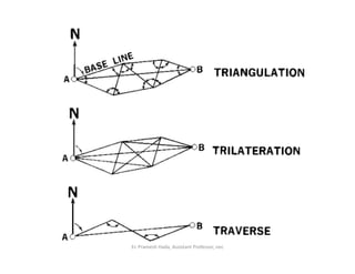
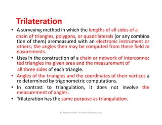
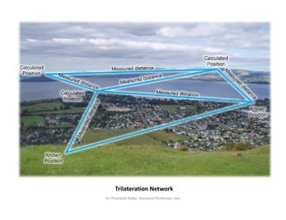
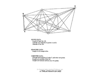
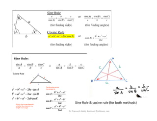
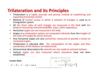
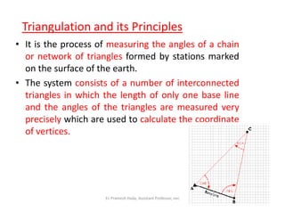
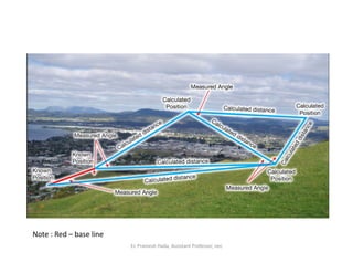
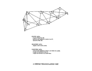
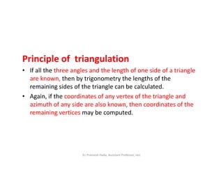
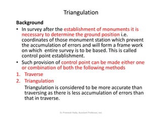
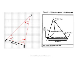
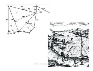
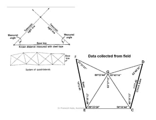
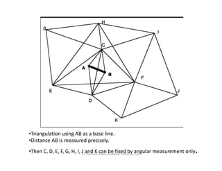
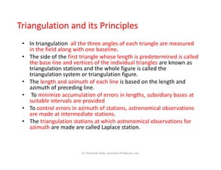
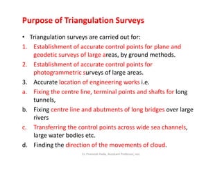
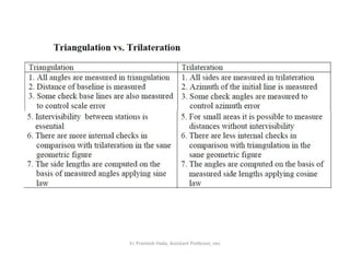

Trilateration and triangulation are surveying methods to establish horizontal control networks. Trilateration involves measuring the lengths of all three sides of triangles without measuring angles, while triangulation measures angles and the length of one base line. Both methods are used to determine coordinate positions through trigonometric computations. Triangulation networks can be classified based on their intended accuracy and purpose, from primary/first order for determining large areas to tertiary/third order for more detailed surveys.


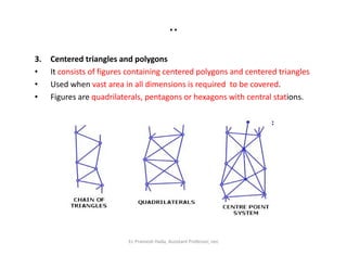
![Microsoft power point distribution systems [read-only]](https://cdn.slidesharecdn.com/ss_thumbnails/diwiuehtrycy7ayewpb3-signature-7f20760b9f97167ae74c1ef33fe58a16817ef3afaab94a37d2a9dfe6de74b684-poli-150822072504-lva1-app6892-thumbnail.jpg?width=640&height=640&fit=bounds)


