
Recommended
Recommended
More Related Content
What's hot
What's hot (20)
Similar to Wall Station Surveys
Similar to Wall Station Surveys (20)
Recently uploaded
Recently uploaded (20)
Wall Station Surveys
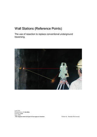
- 1. Wall Stations (Reference Points) The use of resection to replace conventional underground traversing. re.sec.tion Pronunciation: ri-'sek-sh&n Function: noun Date: 1775 : the surgical removal of part of an organ or structure Written by : Brendon McCormack
- 2. Abbssttrraacctt The conventional method of installing survey control in underground mines is by traversing. Survey stations are placed into the backs of the drive or stope. The surveyor positions the theodolite directly under the statio n and back sights another station for orientation. The instrument assumes the Easting and Northing coordinates of the station and the RL is obtained by measuring the height difference from the station to the instrument. This gives the surveyor a reference from which to commence a survey. If resection was performed instead of traversing then surveyors could set up anywhere they wanted, as long as they were in sight of two known points. Survey stations could be as simple as reference points (wall stations) throughout the mine.
- 3. IInnttrroodd uucc ttiioo nn Surveying equipment is rapidly evolving. Some theodolites are motorised and have the capability to sight prisms automatically. They are able to perform mundane tasks without human intervention (for example prism monitoring). With the above technology in mind, the fundamentals of underground mine surveying have not changed in the past one hundred years. Most Mine Surveyors still install survey stations into the backs of the underground workings. Is there a different way of installing survey control in underground mines? Could it be safer, faster, easier to install, easier to use, more accurate or more precise? This paper briefly looks at some of the alternatives, and proposes one of the methods. Alltteerrnnaattiivvee Suurrvveeyy Meetthhooddss A variety of survey stations have been trailed in the underground environment. Floor stations similar to those used on the surface are sometimes installed underground, but are difficult and timely to install, and are often hard to find. Traffic, mud and water make them nearly impossible to use (if they are submerged), and are really only useful in rail drives and mines with concrete (hard formed) floors. This system is more suited too civil engineering projects. Wall stations are another alterna tive; these can come in a variety of forms, one of which consists of a sleeve that is installed into the wall allowing a forced centered bracket to be inserted in (Diagram 1). Once again this system is more suited too civil engineering projects. The obvious shortfalls are drilling a large (30mm) diameter hole, the cost of the sleeves and the time involved in installing the sleeve. Diagram 1 Other wall stations have been permanent structures bolted to the wall similar to survey pillars on the surface (Diagram 2). These in principle are sound but in practice are expensive to make, timely to install, and are easily damaged by mobile equipment as they can protrude from the wall by around 300mm. One small knock to these stations renders them useless.
- 4. Diagram 2 Underground mines usually require hundreds of stations installed to ensure adequate survey control covers all working areas. Any new system must be economically viable before it would be seriously considered over the current methods. The above- mentioned systems could be used in particular areas of underground mines that allow for their installation, for example in completed ventilation drives. But would need to be used in conjunction with another system that was viable to be used throughout the entire mine. A Diiffffee rreenntt Apppprrooaacchh -- Ree sseeccttiioo nn All the previous systems create a reference point from which a theodolite can be set up on, over or under. The reason why these systems have been adopted is to ensure that a quality bearing can be carried throughout the mine. In years gone by, most theodolites could reliably turn high quality angles with ease, but the measurement of a distance with a steel band was an exacting task and required two competent surveyors, a spring balance, and several corrections to obtain a reliable distance to within a few millimeters. Any error in measuring a distance would be carried throughout the traverse, but that error would not compound. Errors in turning an angle would be magnified the further the traverse traveled from that point. With the advancement in surveying equipment, coaxial total stations can now measure reflectorless to rock, and up to 50 m reliably to a prism with mm accuracy. These instruments come with onboard programs tha t allow for a variety of functions to be performed. One program in particular allows the surveyor to perform a resection to two known stations as an alternative to physically setting up on them. Resection is commonly used by mine surveyors to set points out in open pits, but is rarely used underground. The resection program usually follows four main steps. 1. Execute the resection program 2. Type in the name of your temporary point (new position) 3. Type in the name of the first known station, sight and measure to it. 4. Type in the name of the second known station, sight and measure to it.
- 5. The instrument retrieves the selected stations coordinates from a station list, calculates the new station position, and displays the accuracy of the resection, giving an error or standard deviation in the x, y, and z and orientation fields. If these results are accepted the instrument adopts the calculated coordinates and orientation. You are now ready to survey. You have an absolute check on how well you have set up, as the instrument displays the accuracy of the position. No instrument heights or target heights need to be measured, so no gross errors in RL will occur. The Resection in most cases can even determine if you have set the wrong prism constant. The resection observa tion consists of one horizontal angle turned, two vertical angles and two slope distances observed to two known points. Part of the observation is redundant and therefore can be used as a check. Diagram 3 has the known points 1 and 2 as the bold line with the bearing and distance known along this line. The observation is made from the point TP. Observed and reduced information is distances A, B and angle f. The minimum information required to solve the resection is both distances A and B, or the angle turned f and one distance A or B. Diagram 3 Most computer programs and onboard instrument programs use least squares to solve the resection. As this is the case for most applications, and the fact that the calculation checks itself, there is no requirement to manually calculate or check the results. But if a surveyor felt compelled to do so then there are several trigonometric methods available. Method 1 Fix the horizontal angle turned f and the reduced distance A, calculate all other angles a b from this data. With the triangle solved calculate the bearing of line 2 – TP using the known bearing along the line 1 – 2 and angle b. Use this bearing and the distance A to calculate coordinates for TP. This solution is completely independent of distance B. Method 2 Fix the horizontal angle turned f and the reduced distance B, calculate all other angles a b from this data. With the triangle solved calculate the bearing of line 1 – TP using the known bearing along the line 1 – 2 and angle a. Use this bearing and the distance B to calculate coordinates for TP. This solution is completely independent of distance A.
- 6. Method 3 Fix the horizontal angle turned f and the reduced distance B, calculate all other angles a b from this data. With the triangle solved calculate the bearing of line 2 – TP using the known bearing along the line 1 – 2 and angle b. Use this bearing and the distance A to calculate coordinates for TP. This solution uses both distances A and B. Method 4 Fix the horizontal angle turned f and the reduced distance A, calculate all other angles a b from this data. With the triangle solved calculate the bearing of line 1 – TP using the known bearing along the line 1 – 2 and angle a. Use this bearing and the distance B to calculate coordinates for TP. This solution uses both distances A and B. Method 5 Fix the reduced distances A and B calculate angles a b from this data. With the triangle solved calculate the bearing of line 1 – TP using the known bearing along the line 1 – 2 and angle a. Use this bearing and the distance B to calculate coordinates for TP. This solution uses both distances A and B and is independent of angle ? . Reesseecc ttiioo nn –– Soo llvviinngg ffoo rr RL.. The Reduced level of the resection station can be calculated from both known wall stations. The RL of each known point and the observed change in heights is used. No height of instrument or height of sight is required. Waa llll Sttaattiioo nn –– Crr iittee rr iiaa Due to the nature of mining, he ading faces are always advancing. Underground mines with a single heading, can advance on average by 10 to 15 metres per day. This makes station positions redundant quickly, as the optimum position to conduct a survey is usually within 15 meters from the working face. Typically a surveyor sets up under a station, sights back to a reference station, surveys in a forward temporary point (TP), and then sets up on the TP to conduct the survey. If the Surveyor were able to see both stations from the desired TP, there wouldn’t be a need to survey in the TP using conventional methods. The TP could be coordinated and orientated by resection. Of course this method would take some time using conventional back stations, as the Surveyor would need to set up a prism und er each station and measure the prism heights. But in open pits, permanent prisms are mounted to pillars or pit walls and these are used to perform the resection, no target heights are measured, as they are all zero. The great advantage with performing a resection is the reduced number of set ups required to complete a job. In the underground environment it is not practical or economical to permanently mount prisms to the walls, but a system with no target heights would be an advantage.
- 7. For the underground environment a system must satisfy three criteria; It must be: · Robust enough to survive the underground environment · Easy to sight and measure to · Precise enough to repeatedly locate the reference point. With the above criteria in mind, it was decided that the wall station would need to be a two-part system. 1. A prism attached to a stem. 2. A small hole drilled into the wall of a drive or stope with a piece of aluminium tube inside it. The aluminium tube would stay in the wall permanently. The prism and stem would be inserted during the survey and removed afterwards. This system meets the above criteria, as it is robust, with only the aluminium sleeve left in the wall underground. It is easily sighted and measured too and precisely creates the reference point every time. Waa llll Sttaattiioo nn –– Stteem The wall station stem consists of a 200mm length of stainless steel, ~7.5mm diameter at one end designed to fit into the aluminium sleeve, and ~12mm diameter at the other end to lock into the base of a Leica prism. These can be purchased from CR Kennedy Product Code number 602009. Diagram 4 Waa llll Sttaattiioo nn –– Prr iissm The Leica prism and holder were chosen for use with the wall station stem, as it is the only holder (that I'm aware of) with the back of the prism or measure point located truly on the reference. Prism holders with 30mm or 0mm offset are in fact not truly referenced. By this I mean if you rotate the target left or right, the back of the prism actually moves off the line of sight. This is not a problem when the prism is used in a traverse set with a 'sighting target' or when the prism is aligned directly at the observer. But with wall stations the prism is not standing vertical, so a 'sighting target' is useless and alignment of the prism is sometimes difficult as you may not always be able to get your eye behind the prism to line it in.
- 8. Diagram 5 Waa llll Sttaattiioo nn –– Slleeeevvee The wall station sleeve is the physical “survey station” that is found underground. It is simply a hole that aligns and positions the stem and prism to create the reference point or wall station. There are generally two types of wall station sleeves installed in underground mines. One system incorporates a piece of aluminium tube installed into the wall, while the other system is simply a hole drilled into the rock. Wall Station – Sleeve installed into a 12mm diameter hole and fixed with putty (Diagram 6). Diagram 6 Wall Station – Sleeve installed into a 10mm diameter hole. No putty is required to fix the tube into position (Diagram 7).
- 9. Diagram 7 Wall Station – Hole drilled into the rock. Inside hole is drilled with 8mm diameter hole, while the outer collar hole is drilled with a 15mm diameter hole or larger (Diagram 8). The collar hole is important as it signifies the holes actual collar position. Diagram 8 Waa llll Sttaattiioo nn –– Pllaacceemeenntt As with conventional stations the placement of wall stations has a direct impact on the accuracy of the traverse. It is important to maintain the longest distance between stations as is practical. Long base lines (distance between stations) ensure high orientation accuracy. Best solutions are obtained by setting up as close as possible to one Reference Point and sighting the furthest Reference Point. Whhyy Reepp llaa ccee Coonnvveennttiioo nnaa ll Unndd eerrggrroo uunndd Trraavveerrss iinngg?? The most obvious problem with installing survey stations is the hazards involved working at height. The backs of a drive can be up to 7 metres high. Working off an IT platform, nifty lift or ladder exposes the surveyor to an element of danger. In stopes it is sometimes difficult to get equipment in to reach the backs, due to no vehicle access, low clearance, broken dirt, etc.
- 10. Obstructions from services and Ventilation bags make the stations difficult to access and can sometimes render the station useless, requiring another station to be installed away from the obstruction. Strong ventilation makes it difficult to set up under a station using a plumb bob. The only way to overcome this is to turn the ventilation off, or use a zenith plummet or right angle eyepiece. Height of instrument must be measured to obtain instrument RL. These measurements have the potential to become a common source of error in surveying. To eliminate this error from the running traverse, a separate level run or resurvey needs to be conducted regularly. But this does not ensure set out has been performed correctly. Damage to survey stations from mobile equipment or blasts is hard to identify when standing on the ground looking at the backs (around 4 metres). The surveyor needs to be able to get up to the station to inspect it. Bell wire is commonly used to string from stations where it poses a ha zard, as it can hit people in the face, especially personnel operating mobile equipment without windscreens. Because of this hazard many mine personnel remove the bell wire. But bell wire makes the station easier to identify and assists in set up. For reference stations the bell wire allows the surveyor to hang an illuminated back sight. For these reasons it is in the surveyor’s interest to replace the bell wire, which can be time consuming. Back measuring is a requirement to reduce the risk of sighting the wrong station, but the practice is not an absolute check, as another station may exist at a similar distance. The back measure only checks the distance between stations. The underground environment makes conventional traversing challenging. Strict adherence to procedures and techniques is required when performing a conventional traverse. Back measures and other validations must be taken to minimize station identification errors. Production pressures can comprise standards. If a surveyor is running out of time to complete the day’s tasks, then it could be easy to overlook some of the standard checks, as these do not stop the surveyor from completing the job. If no back measure or other check validation is made, then it is difficult to prove that the surve y is correct. It is difficult to identify if a traverse has been compromised. You can’t look at the observations or its results and identify errors in the instrument positioning under the station, positioning of the back sight, or the measurement of the instrument and target height. Trraannss ffeerr oo ff hhee iigghhtt uuss iinngg ccoo nnvveennttiioo nnaa ll bbaacckk ss ttaattiioo nnss
- 11. Underground survey stations are inherent with height problems. Systems used to transfer height using conventional stations are listed below. Conventional traversing is flawed with accumulating errors and potential gross errors in height. The actual measurement datum on the station is not always clearly defined i.e. end of pin, base of ring, etc... The method for measuring the height from the station to instrument and then from the foresight back to the forward station is not always consistent. Mixing measuring equipment like staffs and offset tapes can result in errors. Even if the one system for measuring heights is used accumulating errors can still easily occur. A common cause is to measure a slope distance as a height of the instrument and then measure a true vertical distance at the target. This occurs because the measure points on the instrument are not vertically below the station. (i.e. the instrument is 150mm wide and a height of 3.000m is measured than the actual vertical distance is 2.999m. math’s for vertical height = SQRT(30002 - 752) ). Other sources of error occur when the tape or hook does not catch the ring properly, is interfered with by mesh or some other obstruction, or if the ring has been damaged. Small errors are usually not a problem as resurvey techniques can correct traverses before they become a problem. But gross errors can have immediate impact on all succeeding surveys, until found. Gross errors occur from misreading measurements, transcribing errors, and incorrect signs on height direction. Resurveying using forced centered Temporary stations eliminates or reduces many of the above highlighted errors in conventional surveying. Typically the height at the start and end of the traverse are only measured and the intermediate heights measured as zero. Problems with this method occur when traversing equipment is mixed and matched. If the height of the target is not set exactly to the height of instrument then this difference will accumulate throughout the resurvey. Another shortfall with this technique is that if unacceptable error is found than another survey check is required to identify which station(s) are in error. Levelling is a proven method for the transferring of height. But can be compromised if strict procedures are not followed. The key rule with levelling is to maintain equal back sight and fore sight distances. This ensures that any coning errors with the level are compensated. All levels cone to some degree, a two peg test checks for this error. Levelling up and down declines becomes very time consuming as observation distances are short because sights are restricted to a maximum of ~12 metres ( assume a 1.5m high set up in a decline at 1 in 8). Illumination of the staff can be challenging especially if communication is difficult. Total station Levelling is probably the most suited height transfer method for decline stations, but still requires the Surveyor to measure height differences at the start and end of the heighting. The main disadvantage with all these systems, is there is not one, which will work on its own, you would most likely use the conventional traverse to survey the station
- 12. first, then the Surveyor must come alo ng and level or resurvey the station to check its height. This height will then need changing if an error is found. Many measurements are taken that impact on the transfer of height. If an error is found the checks need to be closed to verify they are correct. Trraannss ffeerr oo ff hhee iigghhtt uuss iinngg waa llll ssttaattiioo nnss aanndd rree sseeccttiioo nn The resection combined with the use of wall stations is a superior method for the transfer of height underground. This is because it is easier, faster and more accurate than any other method. No target or instrument heights are measured, eliminating most of the errors in height transfer. The process of performing the resection is even more accurate than performing reverse trig heighting. Observations are made to the two reference points and the RL of the temporary point is calculated. This RL is calculated from each reference point. The average of these two values is then used as the RL for the instrument. The new wall station is then surveyed and an RL calculated using the observation information and the average RL calculated for the instrument. The next time the new wall station is used in a resection, that information will be compared with another station when the RL of the instrument is calculated. Thus giving an automatic check of the new stations value. Beeaarr iinngg Coonnttrroo ll The Wall station (Reference Point) method of surveying relies heavily on both angles turned and distances measured. As discussed above conventional underground traversing only relies on horizontal angles turned for the bearing control. Therefore in theory the conventional traverse should be a superior method of bearing control. But in practise other errors affect the accuracy of the bearing whilst surveying underground. The main source of error occurs with the positioning of the theodolite under the survey station. A variety of methods are used. A plumb bob strung from the station is a simple technique. Problems with this include ventilation, re-stringing stations, plumb marks on instruments off centre (i.e. battery handles), station rings not hanging true or damaged. A more time consuming but reliable method of set up, is by using a zenith plummet or right angle eyepiece attached to the theodolite. But problems with this method include illuminating the station and identifying the position the ring would lie naturally. Both the above- mentioned systems assume a pin or eyebolt and key ring type station is used. Another method consists of an eyebolt with no key ring. The eyebolt is ground flat on the end and a centre punch used to mark a point. This point is used as the reference for the station.
- 13. The problem with this method is you need to use a zenith plummet every time you use the station, including using it as a backsight. Rust or dust build up can make the reference point hard to identify and illumination is difficult. Errors involved with the above systems are only small; on average (I would estimate that) each set up under a station is in error by around 1 to 3mm. This is not because Surveyors are unskilled or ill equipped but because of the conditions encountered underground make it difficult to achieve higher results. The method of resection eliminates the above errors, as the theodolite is not positioned on, above or below a reference point. But resection is effected by sighting and instrument errors. These can be reduced by observing multiple faces and insuring the instrument is in adjustment, and as mentioned above can be observed with every resection. ATR - available on the Leica TCRA theodolites allows the Surveyor to sight the wall station prisms using automatic target recognition. This reduces sighting errors. Meeaassuurreedd Diiss ttaannccee Conventionally traversed distances are checked by either closing or resurveying the traverse. Back measures are made to check the current set up, but errors of 5mm and greater are often accepted. Resection requires all distances to be measured to a high standard; errors in measurement are reflected in the resection accuracy. If a distance to a station were measured with the wrong prism constant, it would be very difficult to perform a resection using that station without finding errors. This is because distances are not measured along the same line, triangles are used to calculate distances between points, so therefore errors in measurement will have varying effects depending on the geometry of each set up. Gyyrroo Thheeooddoo lliittee Suurrvveeyyss The Gyro theodolite can still be used in conjunction with wall stations to check and correct bearing control. This is done by performing a resection on the two datum wall stations. Set the instrument up close as possible to one datum station (~3 m) ensuring the distance to the other datum station is 30m or more. Run the resection observing two faces to each station. The instrument will display the results, take note of the orientation accuracy if less than 5 seconds, then accept the results. Errors of less than 1mm in position should be achieved. Now survey to the furthest station on both faces and note the instruments bearing. This bearing can be used to reference the gyro. Leave the tribrach and tripod in position. Replace the instrument with the gyro theodolite. Sight the furthest datum station using the previously observed bearing and conduct the gyro observations as normal. Adjustments can be made to the wall stations by calculating join bearing and distances between the stations and adjusting similar to a conventional traverse.
- 14. Eqq uuiippmeenntt Reeqq uuiirreedd Survey Tools Coaxial theodolite Tripod Wall station stem Leica Prism and holder Software Macro or program that has the ability to process the resection. General tools Drill Hammer - To knock the tube into the hole. Hacksaw - To cut the tube into lengths. File - To clean burrs from the inside of the tube Spray bottle - To flush cuttings out of the drilled hole. Consumables Aluminium Tube Paint 10mm masonry drill bit Reedd uunnddaanntt Eqq uuiippmeenntt lLevel llevelling staff loffset tape lzenith plummet lplumb bob lilluminated back sight lladder or nifty lift With conventional survey stations, at least two tripods, tribrachs, posts and prisms are required on a daily basis to survey. With wall stations this equipment is only required for resurveys. This reduced amount of equipment gives Surveyors the flexibility to use spare or pool vehicles when required.
- 15. Clloossee ss aanndd Reessuurrvveeyyss The use of resection underground does NOT eliminate the need for Resurveys. Wall station traverses can be resurveyed and closed the same as a conventional traverse. Coordinate closes are achieved Advvanttagess l No exposure to falls from height. l Easy to install. l Inexpensive consumables. l Easy to inspect for damage. l Self-checking for sleeve damage. l Self-checking of instrument set up. l Self-checking of instrument prism constant. l Absolute station error checks. l Less equipment required. l No instrument heights to measure. Diissadvvanttagess l Complex calculations make manual computation time consuming. l Coaxial instrument required. l Different from current practices. Suummaarryy The fundamentals of underground traversing haven't really changed in the past 100 or so years. EDMs have revolutionised the way we measure distances but the overall method remains the same. In contrast the way voids are surveyed has completely changed. It is only in the past 10 years we have seen the change from offsetting along a cloth tape to reflectorless measurements directly to the rock surface. Drives and stopes can now be surveyed to the highest detail with centimetre accuracy. Inaccessible stopes can now be scanned with tools like the CMS. Theodolites have evolved in leaps and bounds; we have access to coaxial reflectorless instruments that can survey smarter and faster than ever before. The technology has advanced to a point that we now have flexibility in the surveying methods we employ. Wall stations (Reference points) are a step change in the way we can survey underground. They make surveying underground faster, easier, and safer, giving Surveyors confidence in that where they are set up is actually where they should be.