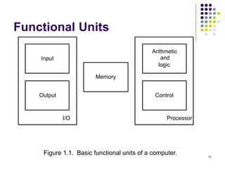
This document provides information about the objectives, outcomes, and modules of a computer organization course. The course aims to explain computer subsystems and their organization, illustrate how programs are executed as machine instructions, and describe memory hierarchy and arithmetic/logical operations. It will also cover the organization of simple and pipelined processors. The course outcomes include explaining basic computer organization and demonstrating how subsystems like the processor, memory, and I/O systems function.


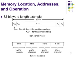
![53
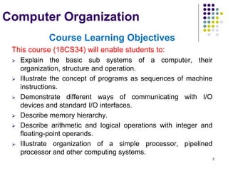
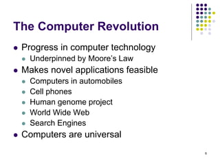
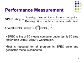
Register Transfer Notation
Identify a location by a symbolic name standing for its
hardware binary address (LOC, PLACE,R0,R1,
DATAIN,DATAOUT…)
Contents of a location are denoted by placing square
brackets around the name of the location (R1←[LOC],
R3 ←[R1]+[R2])
Register Transfer Notation (RTN)
RHS : denotes value
LHS : name of location where value is placed, overwriting old
content of location.](https://image.slidesharecdn.com/module1-221220184920-6f45a2ed/85/Computer-organisation-Module-1-ppt-53-320.jpg)
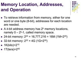
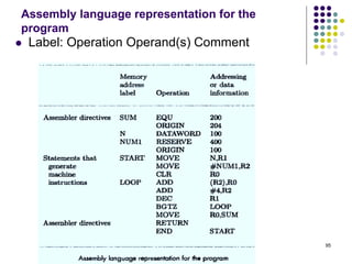
![54
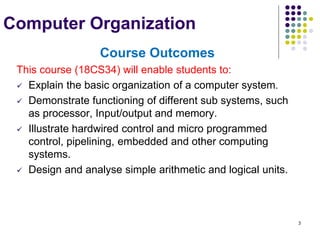
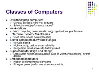
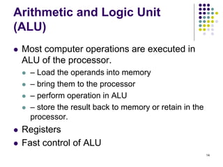
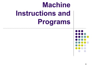
Assembly Language Notation
Represent machine instructions and
programs.
Move LOC, R1 => R1←[LOC]
Add R1, R2, R3 => R3 ←[R1]+[R2]](https://image.slidesharecdn.com/module1-221220184920-6f45a2ed/85/Computer-organisation-Module-1-ppt-54-320.jpg)
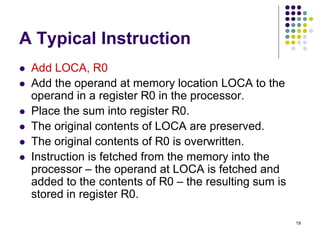
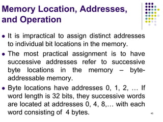
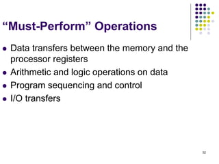
![56
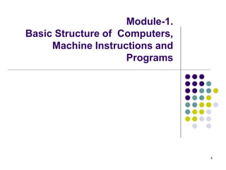
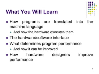
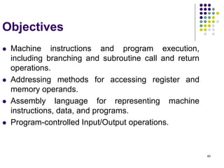
Instruction Formats
C=A+B
Three-Address Instructions
ADD A,B,C C ← [A] + [B]
ADD R2, R3, R1 R1 ← [R2] + [R3]
Two-Address Instructions
ADD A,B B ← [A] + [B]
Move B,C C← [B]
ADD R2, R1 R1 ← [R1] + [R2]
One-Address Instructions
ADD M AC ← [AC] + [M]
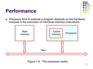
Load A AC ← [A]
Store A A ← [AC]
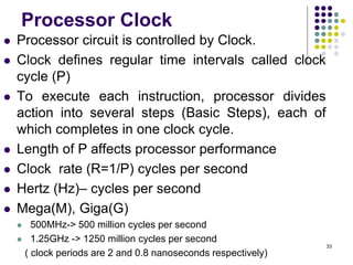
Load A, ADD B, Store C
Zero-Address Instructions
ADD TOS ← [TOS] + [TOS – 1]](https://image.slidesharecdn.com/module1-221220184920-6f45a2ed/85/Computer-organisation-Module-1-ppt-56-320.jpg)
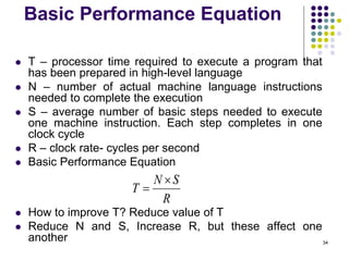
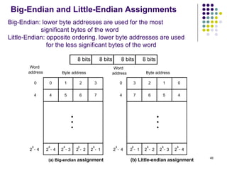
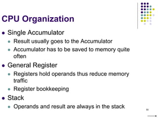
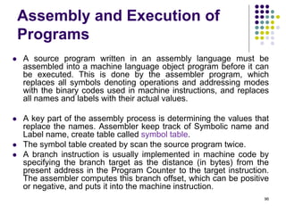
![58
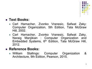
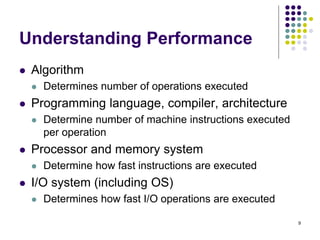
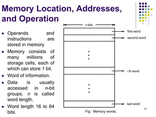
Instruction Formats
Example: Evaluate (A+B) (C+D)
Three-Address
1. ADD A, B, R1 ; R1 ← [A] + [B]
2. ADD C, D, R2 ; R2 ← [C] + [D]
3. MUL R1, R2, X ; X ← [R1] [R2]](https://image.slidesharecdn.com/module1-221220184920-6f45a2ed/85/Computer-organisation-Module-1-ppt-58-320.jpg)
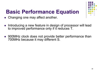
![59
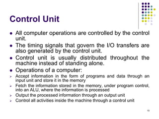
Instruction Formats
Example: Evaluate (A+B) (C+D)
Two-Address
1. MOV A, R1 ; R1 ← [A]
2. ADD B, R1 ; R1 ← [R1] + [B]
3. MOV C, R2 ; R2 ← [C]
4. ADD D, R2 ; R2 ← [R2] + [D]
5. MUL R2, R1 ; R1 ← [R1] [R2]
6. MOV R1, X ; X← [R1]](https://image.slidesharecdn.com/module1-221220184920-6f45a2ed/85/Computer-organisation-Module-1-ppt-59-320.jpg)
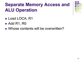
![60
Instruction Formats
Example: Evaluate (A+B) (C+D)
One-Address
1. LOAD A ; AC ← [A]
2. ADD B ; AC ← [AC] + [B]
3. STORE T ; T ← [AC]
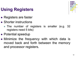
4. LOAD C ; AC ← [C]
5. ADD D ; AC ← [AC] + [D]
6. MUL T ; AC ← [AC] [T]
7. STORE X ; X ← [AC]](https://image.slidesharecdn.com/module1-221220184920-6f45a2ed/85/Computer-organisation-Module-1-ppt-60-320.jpg)
![61
Instruction Formats
Example: Evaluate (A+B) (C+D)
Zero-Address
1. PUSH A ; TOS ← [A]
2. PUSH B ; TOS ← [B]
3. ADD ; TOS ← [A + B]
4. PUSH C ; TOS ← [C]
5. PUSH D ; TOS ← [D]
6. ADD ; TOS ← [C + D]
7. MUL ; TOS ← [C+D][A+B]
8. POP X ; X ← [TOS]](https://image.slidesharecdn.com/module1-221220184920-6f45a2ed/85/Computer-organisation-Module-1-ppt-61-320.jpg)
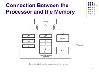
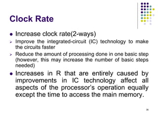
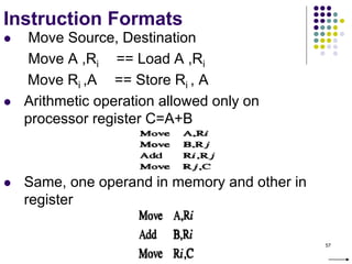
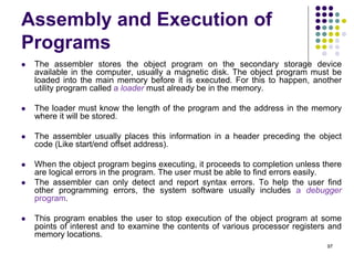
![63
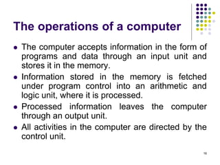
Instruction Execution and
Straight-Line Sequencing
R0,C
B,R0
A,R0
Move
i + 8
Begin execution here Move
i
Contents
Address
C
B
A
the program
Data for
segment
program
3-instruction
Add
i + 4
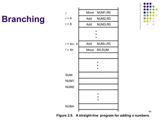
Figure 2.8. A program for C [A] + [B].
Assumptions:
- One memory operand
per instruction
- 32-bit word length
- Memory is byte
addressable
- Full memory address
can be directly specified
in a single-word instruction
Two-phase procedure
-Instruction fetch
-Instruction execute
PC=i](https://image.slidesharecdn.com/module1-221220184920-6f45a2ed/85/Computer-organisation-Module-1-ppt-63-320.jpg)

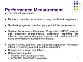
![71
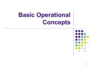
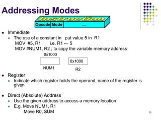
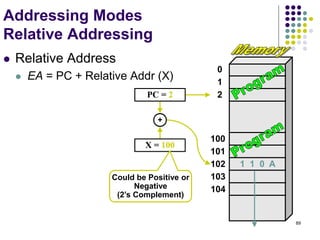
Addressing Modes
The different ways in
which the location of
an operand is
specified in an
instruction are
referred to as
addressing modes.
Name Assem bler syntax Addressing Function
Immediate #Value Operand = Value
Register Ri EA = Ri
Absolute(Direct) LOC EA = LOC
Indirect (Ri ) EA = [Ri ]
(LOC) EA = [LOC]
Index X(Ri) EA = [Ri ] + X
Basewith index (Ri ,Rj ) EA = [Ri ] + [Rj ]
Basewith index X(Ri,Rj ) EA = [Ri ] + [Rj ] + X
and offset
Relative X(PC) EA = [PC] + X
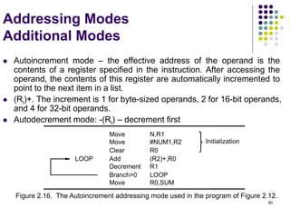
Autoincrement (Ri )+ EA = [Ri ] ;
Increment Ri
Autodecrement (Ri ) Decrement Ri ;
EA = [Ri]
](https://image.slidesharecdn.com/module1-221220184920-6f45a2ed/85/Computer-organisation-Module-1-ppt-71-320.jpg)
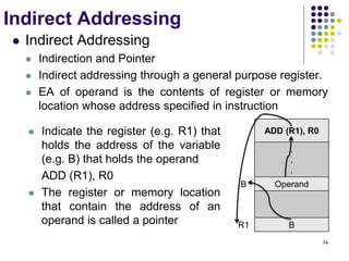
![Indirect Addressing
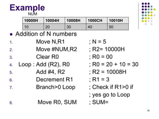
Example
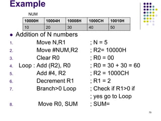
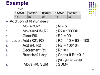
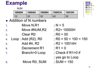
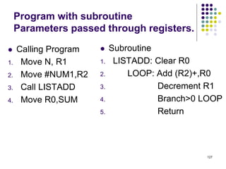
Addition of N numbers
1. Move N,R1 ; N = Numbers to add
2. Move #NUM,R2 ; R2= Address of 1st no.
3. Clear R0 ; R0 = 00
4. Loop : Add (R2), R0 ; R0 = [NUM1] + [R0]
5. Add #4, R2 ; R2= To point to the next
; number
6. Decrement R1 ; R1 = [R1] -1
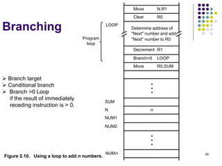
7. Branch>0 Loop ; Check if R1>0 or not if
; yes go to Loop
8. Move R0, SUM ; SUM= Sum of all no.
76](https://image.slidesharecdn.com/module1-221220184920-6f45a2ed/85/Computer-organisation-Module-1-ppt-76-320.jpg)


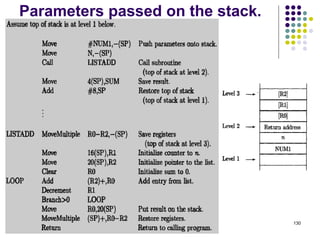
![84
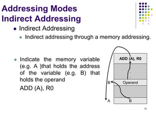
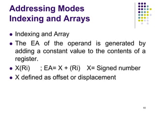
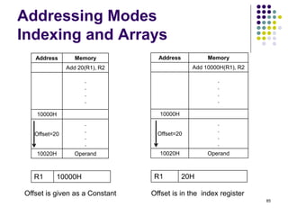
Addressing Modes
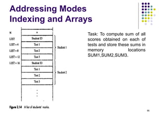
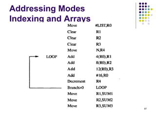
Indexing and Arrays
In general, the Index mode facilitates access to an operand
whose location is defined relative to a reference point within
the data structure in which the operand appears.
Index Addressing Mode
X(Ri) so EA= X+[Ri]
2D Array (Base with Index AM)
(Ri, Rj) so EA = [Ri] + [Rj]
Rj is called the base register
3D Array (Base with Index and offset AM)
X(Ri, Rj) so EA = X + [Ri] + [Rj]](https://image.slidesharecdn.com/module1-221220184920-6f45a2ed/85/Computer-organisation-Module-1-ppt-84-320.jpg)

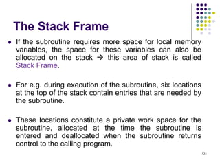
![100
Data Transfer Instructions
Mode Assembly Register Transfer
Direct address LD ADR AC ← M[ADR]
Indirect address LD @ADR AC ← M[M[ADR]]
Relative address LD $ADR AC ← M[PC+ADR]
Immediate operand LD #NBR AC ← NBR
Index addressing LD ADR(X) AC ← M[ADR+XR]
Register LD R1 AC ← R1
Register indirect LD (R1) AC ← M[R1]
Autoincrement LD (R1)+ AC ← M[R1], R1 ← R1+1](https://image.slidesharecdn.com/module1-221220184920-6f45a2ed/85/Computer-organisation-Module-1-ppt-100-320.jpg)

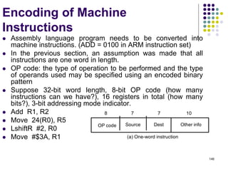
![144
Multiplication and Division
Multiply Ri, Rj
Rj ← [Ri] х [Rj]
2n-bit product case: high-order half in R(j+1)
Divide Ri, Rj
Rj ← [Ri] / [Rj]
Quotient Rj,
Remainder R(j+1)](https://image.slidesharecdn.com/module1-221220184920-6f45a2ed/85/Computer-organisation-Module-1-ppt-144-320.jpg)