Outline
•Accessing I/O Devices
•Interrupts– Interrupt Hardware,
Enabling and Disabling Interrupts
Handling Multiple Devices
• Direct Memory Access:
Bus Arbitration
Speed, size and Cost of memory systems
• Cache Memories – Mapping Functions.
3.
Accessing I/O devices
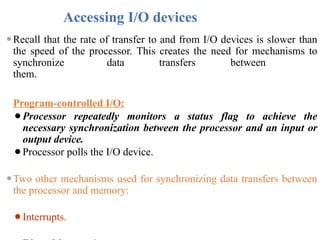
⚫Recallthat the rate of transfer to and from I/O devices is slower than
the speed of the processor. This creates the need for mechanisms to
synchronize data transfers between
them.
Program-controlled I/O:
⚫Processor repeatedly monitors a status flag to achieve the
necessary synchronization between the processor and an input or
output device.
⚫Processor polls the I/O device.
⚫Two other mechanisms used for synchronizing data transfers between
the processor and memory:
⚫Interrupts.
4.
Accessing I/O devices
Bus
I/Odevice 1 I/O device n
Processor Memory
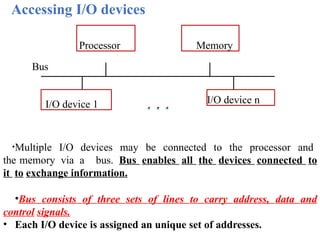
•Multiple I/O devices may be connected to the processor and
the memory via a bus. Bus enables all the devices connected to
it to exchange information.
•Bus consists of three sets of lines to carry address, data and
control signals.
• Each I/O device is assigned an unique set of addresses.
5.
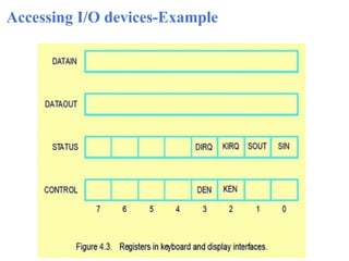
Accessing I/O devices
I/O
interface
Address
decoder
Dataand
status registers
Control
circuits
Input device
Bus
Address lines
Data lines
Control lines
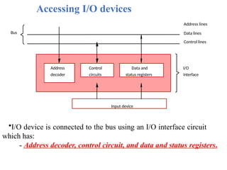
•I/O device is connected to the bus using an I/O interface circuit
which has:
- Address decoder, control circuit, and data and status registers.
6.
Accessing I/O devices
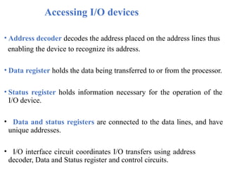
•Address decoder decodes the address placed on the address lines thus
enabling the device to recognize its address.
• Data register holds the data being transferred to or from the processor.
• Status register holds information necessary for the operation of the
I/O device.
• Data and status registers are connected to the data lines, and have
unique addresses.
• I/O interface circuit coordinates I/O transfers using address
decoder, Data and Status register and control circuits.
7.
Accessing I/O devices
•Toaccess an I/O device, the processor places the address on the address
lines.
•The device recognizes the address, and responds to the commands
issued on the control lines.
•The processor requests either a read or a write operation, and
the
requested data are transferred over the data lines.
⚫I/O devices and the memory may share the same address space,
the
arrangement is called Memory-mapped I/O.
⚫Any machine instruction that can access memory can be
used to transfer data to or from an I/O device.
8.
Accessing I/O devices
Mostof the computer systems use memory-mapped I/O.
⚫I/O devices and the memory may have different address spaces:
⚫The advantage is that, I/O devices may have to deal with fewer
address lines.
⚫Special instructions to transfer data to and from I/O devices.
⚫I/O address lines need not be physically separate from memory
address lines.
⚫In fact, address lines may be shared between I/O devices and
memory, with a control signal to indicate whether it is a memory
address or an I/O address.
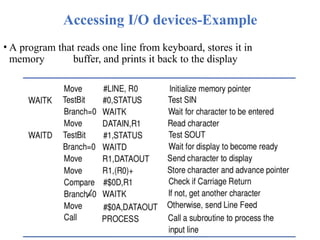
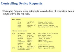
Accessing I/O devices-Example
•A program that reads one line from keyboard, stores it in
memory buffer, and prints it back to the display
11.
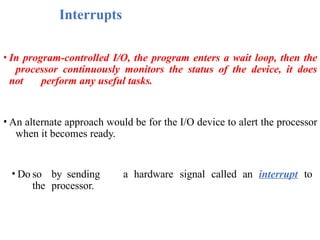
Interrupts
• In program-controlledI/O, the program enters a wait loop, then the
processor continuously monitors the status of the device, it does
not perform any useful tasks.
• An alternate approach would be for the I/O device to alert the processor
when it becomes ready.
• Do so by sending a hardware signal called an interrupt to
the processor.
12.
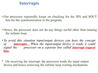
Interrupts
• Our processorrepeatedly keeps on checking for the SIN and SOUT
bits for the synchronization in the program.
• Hence, the processor does not do any things useful other than running
the infinite loop.
• To avoid this situation input/output devices can have the concept
of interrupts . When the input/output device is ready it could
signal the processor on a separate line called interrupt request
line.
• On receiving the interrupt, the processor reads the input output
device and hence removing the infinite loop waiting mechanism.
13.
Interrupts
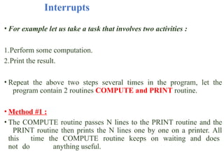
• For examplelet us take a task that involves two activities :
1.Perform some computation.
2.Print the result.
• Repeat the above two steps several times in the program, let the
program contain 2 routines COMPUTE and PRINT routine.
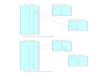
• Method #1 :
• The COMPUTE routine passes N lines to the PRINT routine and the
PRINT routine then prints the N lines one by one on a printer. All
this time the COMPUTE routine keeps on waiting and does
not do anything useful.
14.
Interrupts
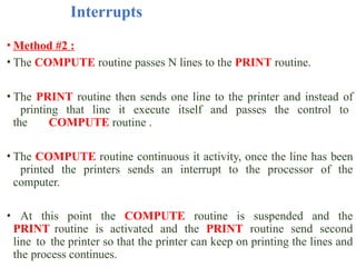
• Method #2:
• The COMPUTE routine passes N lines to the PRINT routine.
• The PRINT routine then sends one line to the printer and instead of
printing that line it execute itself and passes the control to
the COMPUTE routine .
• The COMPUTE routine continuous it activity, once the line has been
printed the printers sends an interrupt to the processor of the
computer.
• At this point the COMPUTE routine is suspended and the
PRINT routine is activated and the PRINT routine send second
line to the printer so that the printer can keep on printing the lines and
the process continues.
15.
Interrupts
• At leastone of the bus control lines, called an
interrupt-request line is dedicated for this purpose.
• Processor can perform other useful
tasks while it is waiting for
the device to be ready.
•When an interrupt occurs, control must be transferred
to the interrupt service routine.
•The routine executed in response to an interrupt
request is called Interrupt Service Routine.
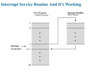
Interrupt Service RoutineAnd It’s
Working
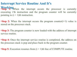
•Step 1: When the interrupt occurs the processor is currently
executing i’th instruction and the program counter will be currently
pointing to (i + 1)th instruction.
•Step 2: When the interrupt occurs the program counter(i+1) value is
stored on the processes stack.
•Step 3: The program counter is now loaded with the address of interrupt
service routine.
•Step 4: Once the interrupt service routine is completed, the address on
the processes stack is pop and place back in the program counter.
•Step 5: Execution resumes from (i + 1)th line of COMPUTE routine.
18.
Interrupts
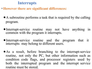
⚫However there aresignificant differences:
⚫A subroutine performs a task that is required by the calling
program.
⚫Interrupt-service routine may not have anything in
common with the program it interrupts.
⚫Interrupt-service routine and the program that it
interrupts may belong to different users.
⚫As a result, before branching to the interrupt-service
routine, not only the PC, but other information such as
condition code flags, and processor registers used by
both the interrupted program and the interrupt service
routine must be stored.
19.
Interrupts
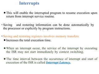
⚫This will enablethe interrupted program to resume execution upon
return from interrupt service routine.
⚫Saving and restoring information can be done automatically by
the processor or explicitly by program instructions.
⚫Saving and restoring registers involves memory transfers:
⚫Increases the total execution time.
⚫When an interrupt occur, the service of the interrupt by executing
the ISR may not start immediately by context switching.
⚫The time interval between the occurrence of interrupt and start of
execution of the ISR is called Interrupt Latency.
20.
Interrupts
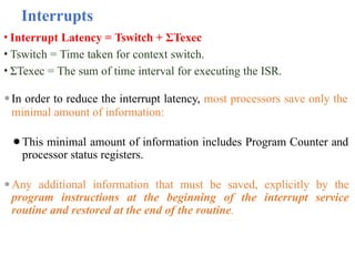
• Interrupt Latency= Tswitch + ΣTexec
• Tswitch = Time taken for context switch.
• ΣTexec = The sum of time interval for executing the ISR.
⚫In order to reduce the interrupt latency, most processors save only the
minimal amount of information:
⚫This minimal amount of information includes Program Counter and
processor status registers.
⚫Any additional information that must be saved, explicitly by the
program instructions at the beginning of the interrupt service
routine and restored at the end of the routine.
21.
Interrupts
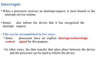
• When aprocessor receives an interrupt-request, it must branch to the
interrupt service routine.
• Itmust also inform the device that it has recognized the
interrupt request.
• This can be accomplished in two ways:
• Some processors have an explicit interrupt-acknowledge
control signal for this purpose.
• In other cases, the data transfer that takes place between the device
and the processor can be used to inform the device.
22.
Interrupt Hardware
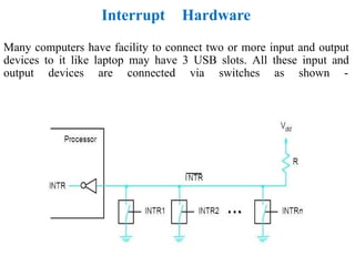
Many computershave facility to connect two or more input and output
devices to it like laptop may have 3 USB slots. All these input and
output devices are connected via switches as shown -
23.
Interrupt Hardware
So thereis a common interrupt line for all N input/output devices and
the interrupt handling works in the following manner ->
1.When no interrupt is issued by the input/output devices then all the
switches are open and the entire voltage from Vdd is flown through
the single line INTR and reaches the processor. Which means the
processor gets a voltage of 1V.
2.When the interrupt is issued by the input/output devices then the
switch associated with the input/output device is closed, so the
entire current now passes via the switches which means the
hardware line reaching the processes i.e INTR line gets
0 voltage.
24.
Interrupt Hardware
This isan indication for the processor that an interrupt has occurred and
the processor needs to identify which input/output device has
triggered the interrupt.
3.The value of INTR is a logical OR of the requests from individual
devices.
4. The resistor R is called as a pull up resistor because it pulls the
line voltage (vdd) to high voltage state when all switches are
open( no interrupt state).
25.
Enabling & DisablingInterrupts
• An interrupt can stop the currently executed program temporarily and
branch to an interrupt service routine.
• An interrupt can occur at any time during the execution of a program.
• Because of the above reasons it may be some time necessary to disable
the interrupt and enable it later on in the program.
• For this reason some processor may provide special machine
instructions such as interrupt enable an interrupt disable that
performs these tasks.
26.
Enabling & DisablingInterrupts
⚫Interrupt-requests interrupt the execution of a program, and may alter
the intended sequence of events:
⚫Sometimes such alterations may be undesirable, and must
not be allowed.
⚫For example, the processor may not want to be interrupted by the
same device while executing its interrupt-service routine.
⚫Processors generally provide the ability to enable and disable
such interruptions as desired.
27.
Enabling & DisablingInterrupts
⚫One simple way is to provide machine instructions such as Interrupt-
enable and Interrupt-disable for this purpose.
⚫To avoid interruption by the same device during the execution of an
interrupt service routine:
⚫First instruction of an interrupt service routine can be
Interrupt- disable.
⚫Last instruction of an interrupt service routine can be
Interrupt- enable.
28.
Edge Triggered Interrupts
⚫Interrupthandling circuit responds only to the leading edge of
the
signal. Such a line is said to be edge-triggered.
⚫ In this case, Processor receives only one request regardless of
how long the line is activated.
⚫So, no need to explicitly disable interrupt requests.
29.
Enabling & DisablingInterrupts
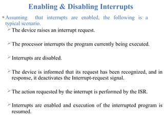
⚫Assuming that interrupts are enabled, the following is a
typical scenario.
The device raises an interrupt request.
The processor interrupts the program currently being executed.
Interrupts are disabled.
The device is informed that its request has been recognized, and in
response, it deactivates the Interrupt-request signal.
The action requested by the interrupt is performed by the ISR.
Interrupts are enabled and execution of the interrupted program is
resumed.
30.
Handling Multiple Devices
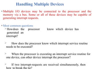
⚫MultipleI/O devices may be connected to the processor and the
memory via a bus. Some or all of these devices may be capable of
generating interrupt requests.
⚫Most common questions
Howdoes the processor know which device has
generated an
interrupt?
How does the processor know which interrupt service routine
needs to be executed?
When the processor is executing an interrupt service routine for
one device, can other device interrupt the processor?
If two interrupt-requests are received simultaneously, then
how to break the tie?
31.
Handling Multiple Devices
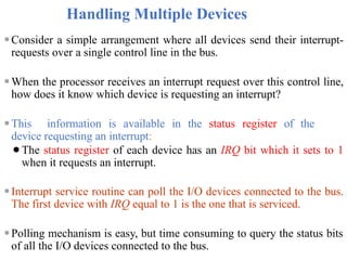
⚫Considera simple arrangement where all devices send their interrupt-
requests over a single control line in the bus.
⚫When the processor receives an interrupt request over this control line,
how does it know which device is requesting an interrupt?
⚫This information is available in the status register of the
device requesting an interrupt:
⚫The status register of each device has an IRQ bit which it sets to 1
when it requests an interrupt.
⚫Interrupt service routine can poll the I/O devices connected to the bus.
The first device with IRQ equal to 1 is the one that is serviced.
⚫Polling mechanism is easy, but time consuming to query the status bits
of all the I/O devices connected to the bus.
32.
Vectored Interrupts
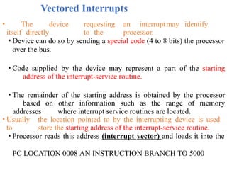
• Thedevice requesting an interruptmay identify
itself directly to the processor.
• Device can do so by sending a special code (4 to 8 bits) the processor
over the bus.
• Code supplied by the device may represent a part of the starting
address of the interrupt-service routine.
• The remainder of the starting address is obtained by the processor
based on other information such as the range of memory
addresses where interrupt service routines are located.
• Usually the location pointed to by the interrupting device is used
to store the starting address of the interrupt-service routine.
• Processor reads this address (interrupt vector) and loads it into the
PC LOCATION 0008 AN INSTRUCTION BRANCH TO 5000
33.
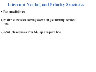
Interrupt Nesting andPriority Sructures
• Two possibilities
1)Multiple requests coming over a single interrupt request
line.
2) Multiple requests over Multiple request line.
34.
Interrupt Nesting
⚫Previously, beforethe processor started executing the interrupt service
routine for a device, it disabled the interrupts from the device.
⚫In general, same arrangement is used when multiple devices can send
interrupt requests to the processor.
⚫During the execution of an interrupt service routine of device, the
processor does not accept interrupt requests from any other device.
⚫Since the interrupt service routines are usually short, the delay that
this causes is generally acceptable.
⚫However, for certain devices this delay may not be acceptable.
⚫Which devices can be allowed to interrupt a processor when
it is executing an interrupt service routine of another device?
35.
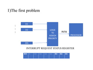
1)The first problem
:
:
:
INTERRUPTREQUEST STATUS REGISTER
D1
D2
DN
LOGIC
TO
ASSIGN
PRIORITY
PROCESSOR
IRM -- ---- ---- ---- ---- IR3 IR2 IR1
36.
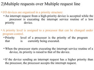
2)Multiple requests overMultiple request line
• I/O devices are organized in a priority structure:
• An interrupt request from a high-priority device is accepted while the
processor is executing the interrupt service routine of a low
priority device.
• A priority level is assigned to a processor that can be changed under
program control.
• Priority level of a processor is the priority of the program
that is currently being executed.
• When the processor starts executing the interrupt service routine of a
device, its priority is raised to that of the device.
• If the device sending an interrupt request has a higher priority than
the processor, the processor accepts the interrupt request.
38.
Interrupt Nesting
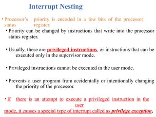
• Processor’spriority is encoded in a few bits of the processor
status register.
• Priority can be changed by instructions that write into the processor
status register.
• Usually, these are privileged instructions, or instructions that can be
executed only in the supervisor mode.
• Privileged instructions cannot be executed in the user mode.
• Prevents a user program from accidentally or intentionally changing
the priority of the processor.
• If there is an attempt to execute a privileged instruction in the
user
mode, it causes a special type of interrupt called as privilege exception.
40.
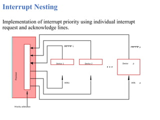
Interrupt Nesting
Implementation ofinterrupt priority using individual interrupt
request and acknowledge lines.
Priority arbitration
Device 1 Device 2 Device p
Processor
INTA1
I N T R 1 I N T R p
INTA p
41.
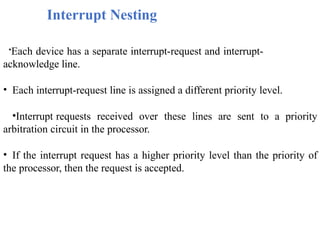
Interrupt Nesting
•Each devicehas a separate interrupt-request and interrupt-
acknowledge line.
• Each interrupt-request line is assigned a different priority level.
•Interrupt requests received over these lines are sent to a priority
arbitration circuit in the processor.
• If the interrupt request has a higher priority level than the priority of
the processor, then the request is accepted.
42.
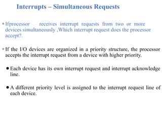
Interrupts – SimultaneousRequests
⚫Ifprocessor receives interrupt requests from two or more
devices simultaneously ,Which interrupt request does the processor
accept?.
⚫If the I/O devices are organized in a priority structure, the processor
accepts the interrupt request from a device with higher priority.
⚫Each device has its own interrupt request and interrupt acknowledge
line.
⚫A different priority level is assigned to the interrupt request line of
each device.
43.
Interrupts – SimultaneousRequests
1.Polling scheme:
•Processor uses a polling mechanism to poll the status registers of
I/O devices to determine which device is requesting an interrupt.
• Inthis case the priority is determined by the order in which
the
devices are polled.
• The first device with status bit set to 1 is the device whose interrupt
request is accepted.
44.
Interrupts – SimultaneousRequests
Processor
Device 2
I N T R
INTA
Device
n
Device 1
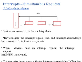
2.Daisy chain scheme:
• Devices are connected to form a daisy chain.
•Devices share the interrupt-request line, and interrupt-acknowledge
line is connected to form a daisy chain.
• When devices raise an interrupt request, the interrupt-
request
line(INTR) is activated.
45.
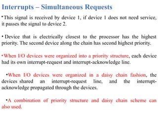
Interrupts – SimultaneousRequests
•This signal is received by device 1, if device 1 does not need service,
it passes the signal to device 2.
• Device that is electrically closest to the processor has the highest
priority. The second device along the chain has second highest priority.
•When I/O devices were organized into a priority structure, each device
had its own interrupt-request and interrupt-acknowledge line.
•When I/O devices were organized in a daisy chain fashion, the
devices shared an interrupt-request line, and the interrupt-
acknowledge propagated through the devices.
•A combination of priority structure and daisy chain scheme can
also used.
46.
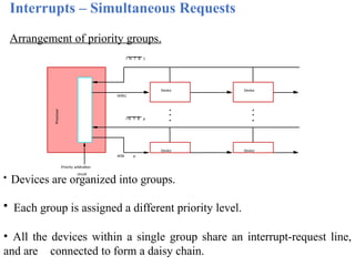
Interrupts – SimultaneousRequests
Arrangement of priority groups.
Device Device
circuit
Priority arbitration
Processor
Device Device
I N T R 1
I N T R p
INTA1
INTA p
• Devices are organized into groups.
• Each group is assigned a different priority level.
• All the devices within a single group share an interrupt-request line,
and are connected to form a daisy chain.
47.
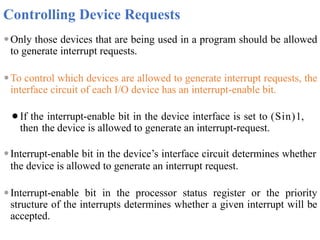
Controlling Device Requests
⚫Onlythose devices that are being used in a program should be allowed
to generate interrupt requests.
⚫To control which devices are allowed to generate interrupt requests, the
interface circuit of each I/O device has an interrupt-enable bit.
⚫If the interrupt-enable bit in the device interface is set to (Sin)1,
then the device is allowed to generate an interrupt-request.
⚫Interrupt-enable bit in the device’s interface circuit determines whether
the device is allowed to generate an interrupt request.
⚫Interrupt-enable bit in the processor status register or the priority
structure of the interrupts determines whether a given interrupt will be
accepted.
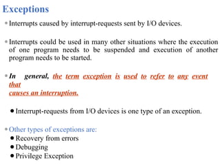
Exceptions
⚫Interrupts caused byinterrupt-requests sent by I/O devices.
⚫Interrupts could be used in many other situations where the execution
of one program needs to be suspended and execution of another
program needs to be started.
⚫In general, the term exception is used to refer to any event
that
causes an interruption.
⚫Interrupt-requests from I/O devices is one type of an exception.
⚫Other types of exceptions are:
⚫Recovery from errors
⚫Debugging
⚫Privilege Exception
51.
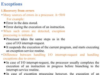
Exceptions
1.Recovery from errors
⚫Manysources of errors in a processor. A=50/0
For example:
⚫Error in the data stored.
⚫Error during the execution of an instruction.
⚫When such errors are detected, exception
processing is initiated.
⚫Processor takes the same steps as in the
case of I/O interrupt-request.
⚫It suspends the execution of the current program, and starts executing
an exception-service routine.
⚫Difference between handling I/O interrupt-request and handling
exceptions due to errors:
⚫In case of I/O interrupt-request, the processor usually completes the
execution of an instruction in progress before branching to the
interrupt-service routine.
⚫In case of exception processing however, the execution of an
52.
Exceptions
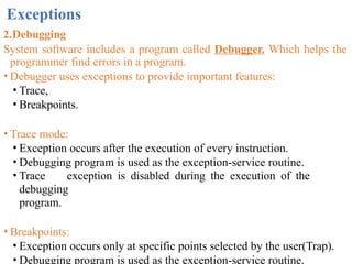
2.Debugging
System software includesa program called Debugger. Which helps the
programmer find errors in a program.
• Debugger uses exceptions to provide important features:
• Trace,
• Breakpoints.
• Trace mode:
• Exception occurs after the execution of every instruction.
• Debugging program is used as the exception-service routine.
• Trace exception is disabled during the execution of the
debugging
program.
• Breakpoints:
• Exception occurs only at specific points selected by the user(Trap).
• Debugging program is used as the exception-service routine.
53.
Exceptions
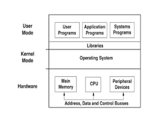
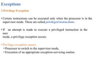
3.Privilege Exception
• Certaininstructions can be executed only when the processor is in the
supervisor mode. These are called privileged instructions.
• If an attempt is made to execute a privileged instruction in the
user
mode, a privilege exception occurs.
• Privilege exception causes:
• Processor to switch to the supervisor mode,
• Execution of an appropriate exception-servicing routine.
54.
Direct Memory
Access(DMA)
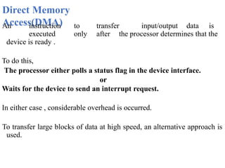
An instructionto transfer input/output data is
executed only after the processor determines that the
device is ready .
To do this,
The processor either polls a status flag in the device interface.
or
Waits for the device to send an interrupt request.
In either case , considerable overhead is occurred.
To transfer large blocks of data at high speed, an alternative approach is
used.
55.
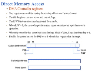
Direct Memory Access
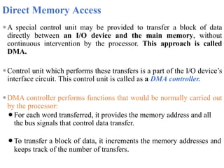
⚫Aspecial control unit may be provided to transfer a block of data
directly between an I/O device and the main memory, without
continuous intervention by the processor. This approach is called
DMA.
⚫Control unit which performs these transfers is a part of the I/O device’s
interface circuit. This control unit is called as a DMA controller.
⚫DMA controller performs functions that would be normally carried out
by the processor:
⚫For each word transferred, it provides the memory address and all
the bus signals that control data transfer.
⚫To transfer a block of data, it increments the memory addresses and
keeps track of the number of transfers.
56.
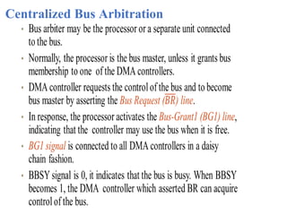
Direct Memory
Access
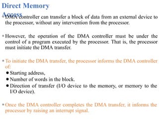
⚫DMA controllercan transfer a block of data from an external device to
the processor, without any intervention from the processor.
⚫However, the operation of the DMA controller must be under the
control of a program executed by the processor. That is, the processor
must initiate the DMA transfer.
⚫To initiate the DMA transfer, the processor informs the DMA controller
of:
⚫Starting address,
⚫Number of words in the block.
⚫Direction of transfer (I/O device to the memory, or memory to the
I/O device).
⚫Once the DMA controller completes the DMA transfer, it informs the
processor by raising an interrupt signal.
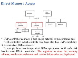
Direct Memory Access
Processor
Systembus
Main
memory
Keyboard
Disk/DMA
controller Printer
DMA
controller
Disk
Disk
• DMA controller connects a high-speed network to the computer bus.
•Disk controller, which controls two disks also has DMA capability.
It provides two DMA channels.
•It can perform two independent DMA operations, as if each disk
has its own DMA controller. The registers to store the memory
address, word count and status and control information are duplicated.
Network
Interface
59.
Direct Memory
Access
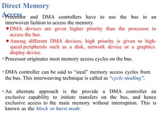
⚫Processor andDMA controllers have to use the bus in an
interwoven fashion to access the memory.
⚫DMA devices are given higher priority than the processor to
access the bus.
⚫Among different DMA devices, high priority is given to high-
speed peripherals such as a disk, network device or a graphics
display device.
⚫Processor originates most memory access cycles on the bus.
⚫DMA controller can be said to “steal” memory access cycles from
the bus. This interweaving technique is called as “cycle stealing”.
⚫An alternate approach is the provide a DMA controller an
exclusive capability to initiate transfers on the bus, and hence
exclusive access to the main memory without interruption. This is
known as the block or burst mode.
60.
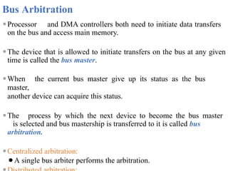
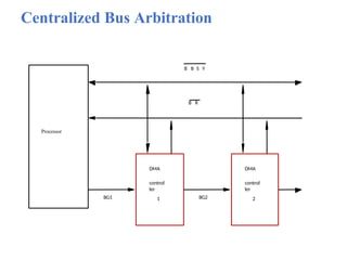
Bus Arbitration
⚫Processor andDMA controllers both need to initiate data transfers
on the bus and access main memory.
⚫The device that is allowed to initiate transfers on the bus at any given
time is called the bus master.
⚫When the current bus master give up its status as the bus
master,
another device can acquire this status.
⚫The process by which the next device to become the bus master
is selected and bus mastership is transferred to it is called bus
arbitration.
⚫Centralized arbitration:
⚫A single bus arbiter performs the arbitration.
61.
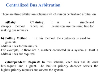
Centralized Bus Arbitration
Thereare three arbitration schemes which run on centralized arbitration.
a)Daisy Chaining: It is a simple and
cheaper method where all the masters use the same line for
making bus requests.
b) Polling Method: In this method, the controller is used to
generate
address lines for the master.
For example, if there are 8 masters connected in a system at least 3
address lines are required.
c)Independent Request: In this scheme, each bus has its own
bus request and a grant. The built-in priority decoder selects the
highest priority requests and asserts the system.
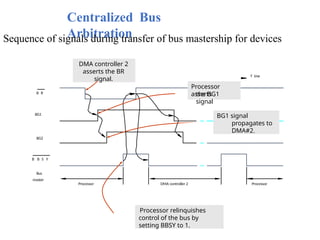
Centralized Bus
Arbitration
Sequence ofsignals during transfer of bus mastership for devices
B B S Y
Bus
master
BG1
BG2
B R
Processor DMA controller 2 Processor
T ime
DMA controller 2
asserts the BR
signal.
Processor
asserts
the BG1
signal
BG1 signal
propagates to
DMA#2.
Processor relinquishes
control of the bus by
setting BBSY to 1.
65.
Centralized Bus
Arbitration
Advantages –
•Thismethod does not favor any particular device and processor.
•The method is also quite simple.
•If one device fails then the entire system will not stop
working.
Disadvantages –
•Adding bus masters is difficult as increases the number of
address lines of the circuit.
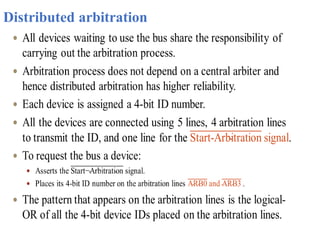
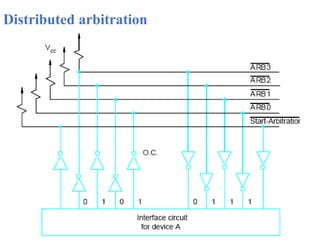
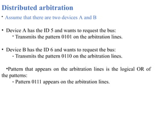
Distributed arbitration
• Assumethat there are two devices A and B
• Device A has the ID 5 and wants to request the bus:
- Transmits the pattern 0101 on the arbitration lines.
• Device B has the ID 6 and wants to request the bus:
- Transmits the pattern 0110 on the arbitration lines.
•Pattern that appears on the arbitration lines is the logical OR of
the patterns:
- Pattern 0111 appears on the arbitration lines.
69.
Distributed arbitration
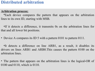
Arbitration process:
•Eachdevice compares the pattern that appears on the arbitration
lines to its own ID, starting with MSB.
•If it detects a difference, it transmits 0s on the arbitration lines for
that and all lower bit positions.
• Device A compares its ID 5 with a pattern 0101 to pattern 0111.
•It detects a difference on line ARB1, as a result, it disables its
drivers on lines ARB1 and ARB0.This causes the pattern 0100 on the
arbitration lines.
• The pattern that appears on the arbitration lines is the logical-OR of
0100 and 0110, which is 0110.
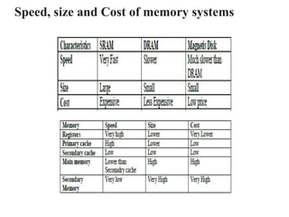
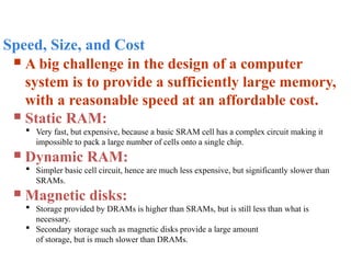
Speed, Size, andCost
A big challenge in the design of a computer
system is to provide a sufficiently large memory,
with a reasonable speed at an affordable cost.
Static RAM:
Very fast, but expensive, because a basic SRAM cell has a complex circuit making it
impossible to pack a large number of cells onto a single chip.
Dynamic RAM:
Simpler basic cell circuit, hence are much less expensive, but significantly slower than
SRAMs.
Magnetic disks:
Storage provided by DRAMs is higher than SRAMs, but is still less than what is
necessary.
Secondary storage such as magnetic disks provide a large amount
of storage, but is much slower than DRAMs.
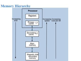
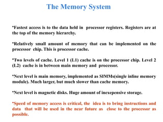
The Memory System
•Fastestaccess is to the data held in processor registers. Registers are at
the top of the memory hierarchy.
•Relatively small amount of memory that can be implemented on the
processor chip. This is processor cache.
•Two levels of cache. Level 1 (L1) cache is on the processor chip. Level 2
(L2) cache is in between main memory and processor.
•Next level is main memory, implemented as SIMMs(single inline memory
module). Much larger, but much slower than cache memory.
•Next level is magnetic disks. Huge amount of inexepensive storage.
•Speed of memory access is critical, the idea is to bring instructions and
data that will be used in the near future as close to the processor as
possible.
74.
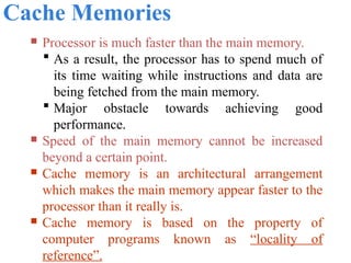
Cache Memories
Processoris much faster than the main memory.
As a result, the processor has to spend much of
its time waiting while instructions and data are
being fetched from the main memory.
Major obstacle towards achieving good
performance.
Speed of the main memory cannot be increased
beyond a certain point.
Cache memory is an architectural arrangement
which makes the main memory appear faster to the
processor than it really is.
Cache memory is based on the property of
computer programs known as “locality of
reference”.
75.
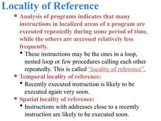
Locality of Reference
Analysis of programs indicates that many
instructions in localized areas of a program are
executed repeatedly during some period of time,
while the others are accessed relatively less
frequently.
These instructions may be the ones in a loop,
nested loop or few procedures calling each other
repeatedly. This is called “locality of reference”.
Temporal locality of reference:
Recently executed instruction is likely to be
executed again very soon.
Spatial locality of reference:
Instructions with addresses close to a recently
instruction are likely to be executed soon.
76.
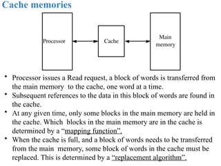
Cache memories
• Processorissues a Read request, a block of words is transferred from
the main memory to the cache, one word at a time.
• Subsequent references to the data in this block of words are found in
the cache.
• At any given time, only some blocks in the main memory are held in
the cache. Which blocks in the main memory are in the cache is
determined by a “mapping function”.
• When the cache is full, and a block of words needs to be transferred
from the main memory, some block of words in the cache must be
replaced. This is determined by a “replacement algorithm”.
Cache
Main
memory
Processor
77.
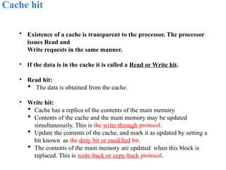
Cache hit
• Existenceof a cache is transparent to the processor. The processor
issues Read and
Write requests in the same manner.
• If the data is in the cache it is called a Read or Write hit.
• Read hit:
The data is obtained from the cache.
• Write hit:
Cache has a replica of the contents of the main memory.
Contents of the cache and the main memory may be updated
simultaneously. This is the write-through protocol.
Update the contents of the cache, and mark it as updated by setting a
bit known as the dirty bit or modified bit.
The contents of the main memory are updated when this block is
replaced. This is write-back or copy-back protocol.
78.
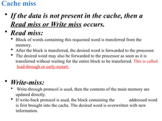
Cache miss
• Ifthe data is not present in the cache, then a
Read miss or Write miss occurs.
• Read miss:
Block of words containing this requested word is transferred from the
memory.
After the block is transferred, the desired word is forwarded to the processor.
The desired word may also be forwarded to the processor as soon as it is
transferred without waiting for the entire block to be transferred. This is called
load-through or early-restart.
• Write-miss:
Write-through protocol is used, then the contents of the main memory are
updated directly.
If write-back protocol is used, the block containing the addressed word
is first brought into the cache. The desired word is overwritten with new
information.
79.
Cache Coherence Problem
•A bit called as “valid bit” is provided for each block.
• If the block contains valid data, then the bit is set to 1, else it is 0.
• Valid bits are set to 0, when the power is just turned on.
• When a block is loaded into the cache for the first time, the valid bit is
set to 1.
• Data transfers between main memory and disk occur directly bypassing
the cache.
• When the data on a disk changes, the main memory block is also
updated.
• However, if the data is also resident in the cache, then the valid bit is
set to 0.
• What happens if the data in the disk and main memory changes and the
write-back protocol is being used?
• In this case, the data in the cache may also have changed and is
indicated by the dirty bit.
• The copies of the data in the cache, and the main memory are different.
This is called the cache coherence problem.
• One option is to force a write-back before the main memory is updated
from the disk.
80.
Mapping functions
Mappingfunctions determine how memory blocks
are placed in the cache.
A simple processor example:
Cache consisting of 128 blocks of 16 words
each.
Total size of cache is 2048 (2K) words.
Main memory is addressable by a 16-bit address.
Main memory has 64K words.
Main memory has 4K blocks of 16 words each.
Three mapping functions:
Direct mapping
Associative mapping
Set-associative mapping.
81.
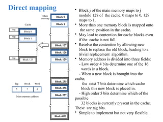
Direct mapping
Main
memory
Block 0
Block1
Block 127
Block 128
Block 129
Block 255
Block 256
Block 257
Block 4095
7 4
Main memory address
Tag Block Word
5
tag
tag
tag
Cache
Block 0
Block 1
Block 127
• Block j of the main memory maps to j
modulo 128 of the cache. 0 maps to 0, 129
maps to 1.
• More than one memory block is mapped onto
the same position in the cache.
• May lead to contention for cache blocks even
if the cache is not full.
• Resolve the contention by allowing new
block to replace the old block, leading to a
trivial replacement algorithm.
• Memory address is divided into three fields:
- Low order 4 bits determine one of the 16
words in a block.
- When a new block is brought into the
cache,
the next 7 bits determine which cache
block this new block is placed in.
- High order 5 bits determine which of the
possible
32 blocks is currently present in the cache.
These are tag bits.
• Simple to implement but not very flexible.
82.
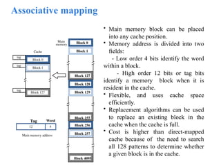
Associative mapping
• Mainmemory block can be placed
into any cache position.
• Memory address is divided into two
fields:
- Low order 4 bits identify the word
within a block.
- High order 12 bits or tag bits
identify a memory block when it is
resident in the cache.
• Flexible, and uses cache space
efficiently.
• Replacement algorithms can be used
to replace an existing block in the
cache when the cache is full.
• Cost is higher than direct-mapped
cache because of the need to search
all 128 patterns to determine whether
a given block is in the cache.
Main
memory Block 0
Block 1
Block 127
Block 128
Block 129
Block 255
Block 256
Block 257
Block 4095
4
Main memory address
Tag Word
12
tag
tag
tag
Cache
Block 0
Block 1
Block 127
83.
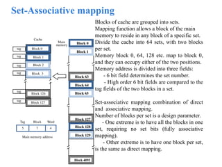
Set-Associative mapping
Blocks ofcache are grouped into sets.
Mapping function allows a block of the main
memory to reside in any block of a specific set.
Divide the cache into 64 sets, with two blocks
per set.
Memory block 0, 64, 128 etc. map to block 0,
and they can occupy either of the two positions.
Memory address is divided into three fields:
- 6 bit field determines the set number.
- High order 6 bit fields are compared to the
tag fields of the two blocks in a set.
Set-associative mapping combination of direct
and associative mapping.
Number of blocks per set is a design parameter.
- One extreme is to have all the blocks in one
set, requiring no set bits (fully associative
mapping).
- Other extreme is to have one block per set,
is the same as direct mapping.
Main
memory Block 0
Block 1
Block 63
Block 64
Block 65
Block 127
Block 128
Block 129
Block 4095
7 4
Main memory address
Tag Block Word
5
tag
tag
tag
Cache
Block 1
Block 2
Block 126
Block 127
Block 3
Block 0
tag
tag
tag