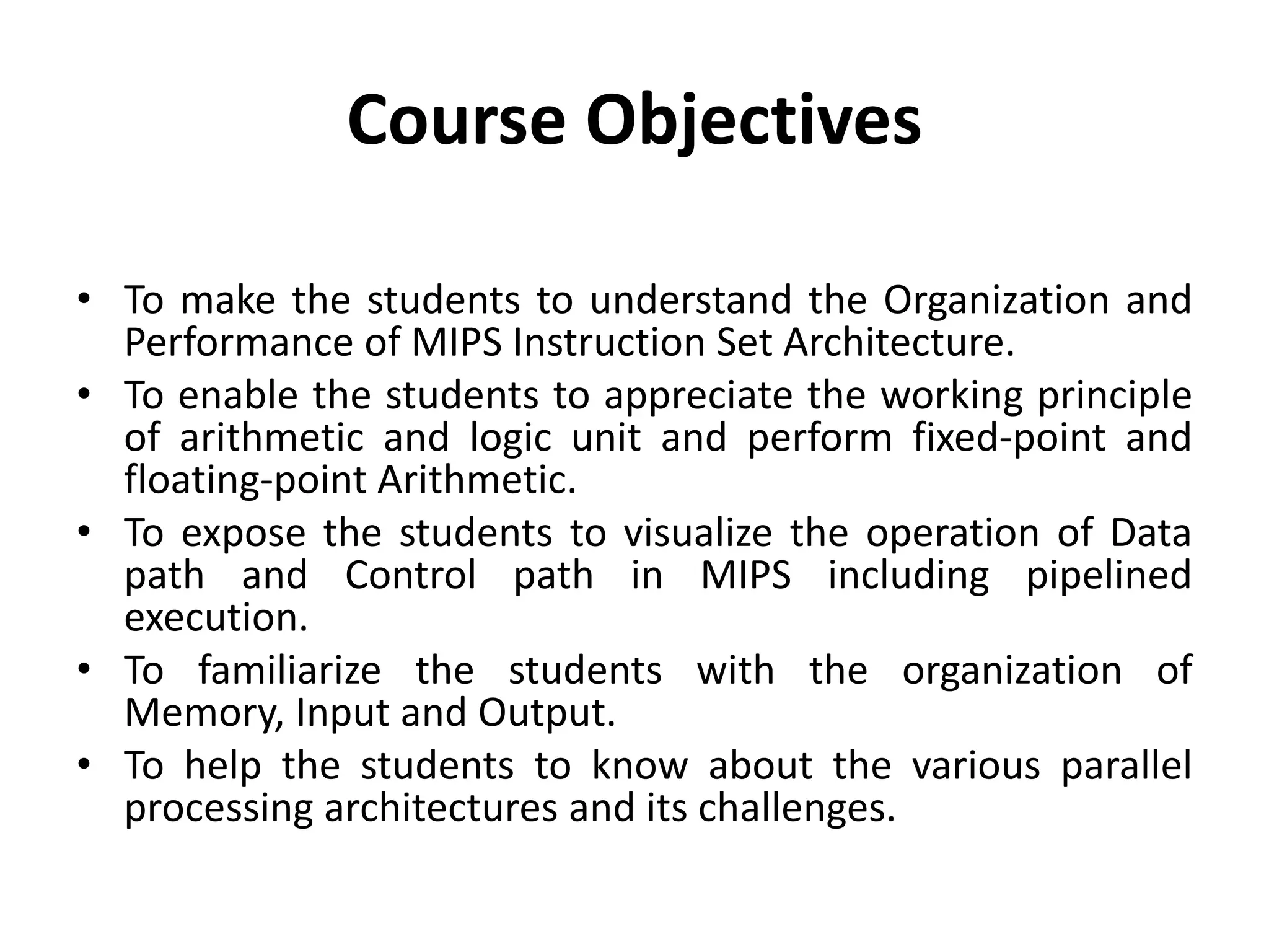
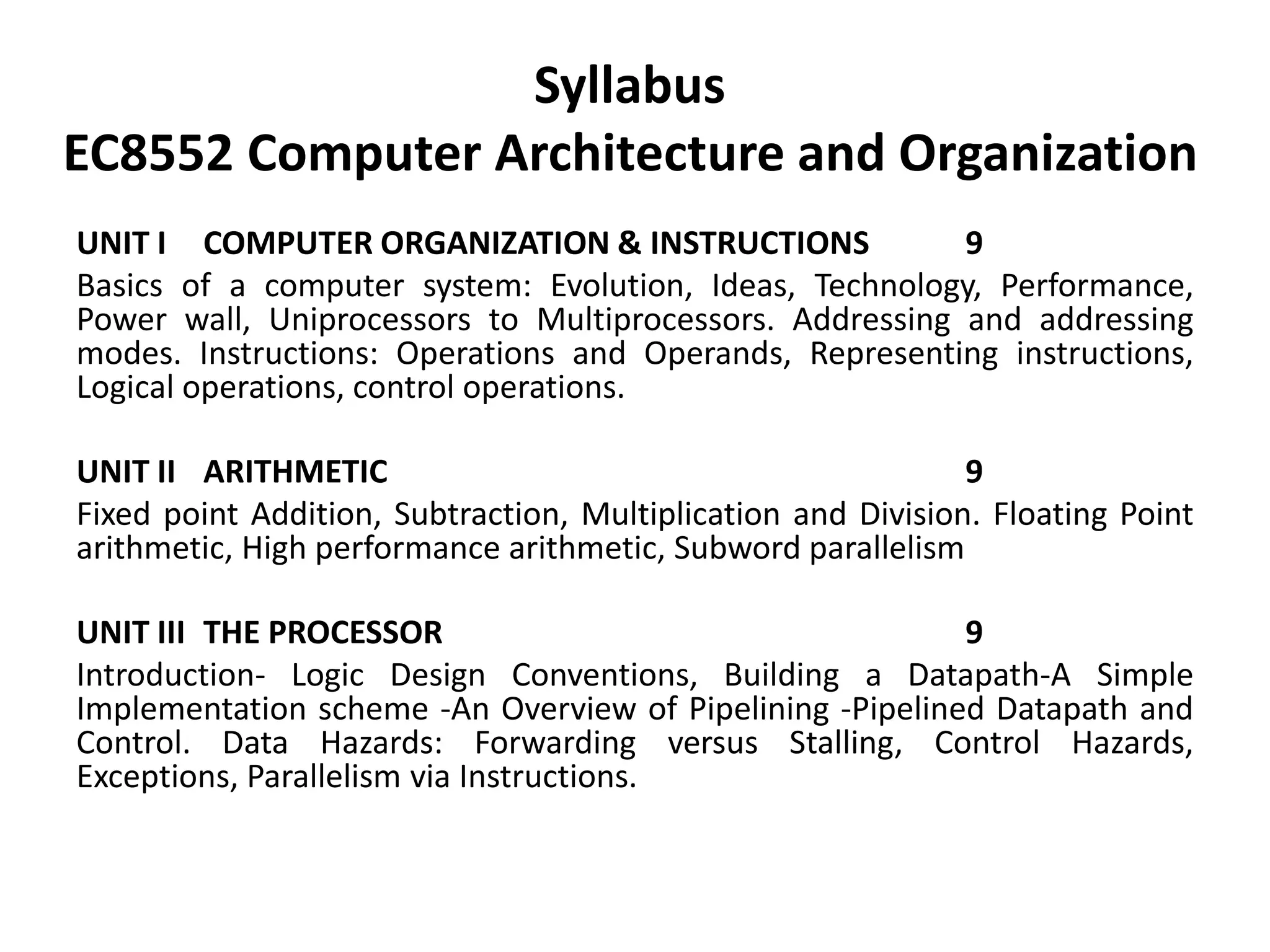
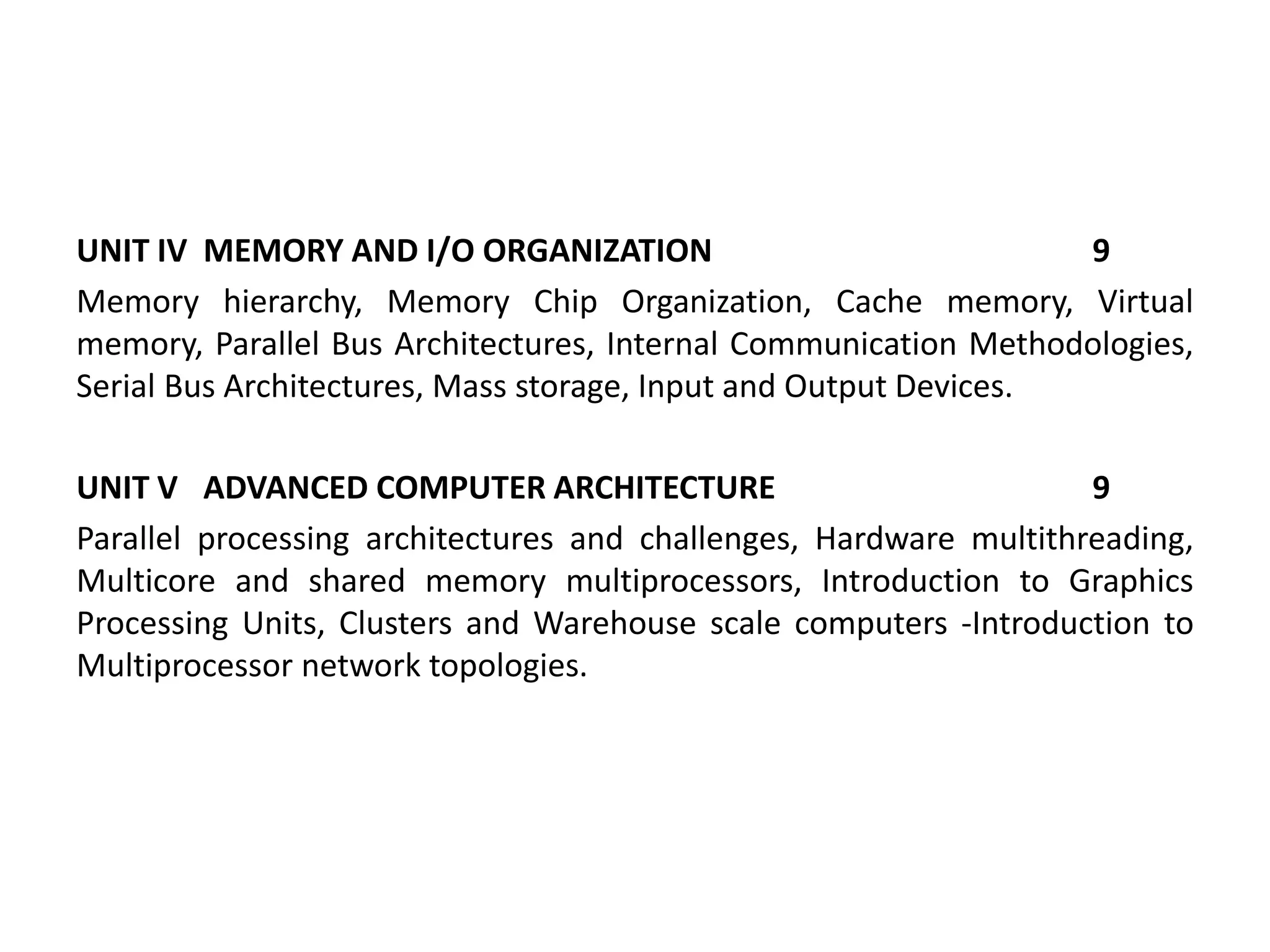
EC8552
Computer Architecture and Organization
Course Objectives
• To make the students to understand the Organization and
Performance of MIPS Instruction Set Architecture.
• To enable the students to appreciate the working principle
of arithmetic and logic unit and perform fixed-point and
floating-point Arithmetic.
• To expose the students to visualize the operation of Data
path and Control path in MIPS including pipelined
execution.
• To familiarize the students with the organization of
Memory, Input and Output.
• To help the students to know about the various parallel
processing architectures and its challenges.
Course Outcomes
After completion of the course, it is expected that the students
will be able to
1. Analyze the performance of the computer system and
understand different instruction formats in MIPS
architecture.
2. Illustrate the Internals of Arithmetic and Logic unit for fixed-
point and floating-point operations.
3. Describe the purposes of data path and control path,
pipelined execution of instructions and its hazards.
4. Explain the various memory organizations with its
performance, Internal Communication methodologies for
I/O devices.
5. Interpret the various parallel processing architectures,
principles and their challenges.
Assessments
Direct Assessments
• Three Internal Assessment Tests
Indirect Assessments
• Five Online Quiz
• Five Assignments
• Six Tutorials
Canvas
https://canvas.instructure.com/courses/1605342
• Course Survey
• Diagnostic Test
Syllabus
EC8552 Computer Architecture and Organization
UNIT I COMPUTER ORGANIZATION & INSTRUCTIONS 9
Basics of a computer system: Evolution, Ideas, Technology, Performance,
Power wall, Uniprocessors to Multiprocessors. Addressing and addressing
modes. Instructions: Operations and Operands, Representing instructions,
Logical operations, control operations.
UNIT II ARITHMETIC 9
Fixed point Addition, Subtraction, Multiplication and Division. Floating Point
arithmetic, High performance arithmetic, Subword parallelism
UNIT III THE PROCESSOR 9
Introduction- Logic Design Conventions, Building a Datapath-A Simple
Implementation scheme -An Overview of Pipelining -Pipelined Datapath and
Control. Data Hazards: Forwarding versus Stalling, Control Hazards,
Exceptions, Parallelism via Instructions.
UNIT IV MEMORY AND I/O ORGANIZATION 9
Memory hierarchy, Memory Chip Organization, Cache memory, Virtual
memory, Parallel Bus Architectures, Internal Communication Methodologies,
Serial Bus Architectures, Mass storage, Input and Output Devices.
UNIT V ADVANCED COMPUTER ARCHITECTURE 9
Parallel processing architectures and challenges, Hardware multithreading,
Multicore and shared memory multiprocessors, Introduction to Graphics
Processing Units, Clusters and Warehouse scale computers -Introduction to
Multiprocessor network topologies.
Computer Architecture - Definition
• Computer architecture is a specification
detailing how a set of software and hardware
technology standards interact to form a
computer system or platform.
• In short, computer architecture refers to how
a computer system is designed and what
technologies it is compatible with.
Computer Architecture and
Organization
• A computer's architecture is its abstract model and is
the programmer's view in terms of instructions,
addressing modes and registers.
• A computer's organization expresses the realization of
the architecture.
• Architecture describes what the computer does and
organization describes how it does it.
• Von Neumann Architecture – Stored Program Concept
• Harvard Architecture
• AC based Architecture
Difference between Architecture and
Organization
• Computer Architecture is the “What”.
• Computer Organization is the “How”.
• CA tells you what the system does. So, knowing
about the architecture is basically knowing what
functionalities will your system display. What you
can expect to get out of it.
• CO tells you how exactly all units in your system
have been arranged and interconnected to help
realize the architectural goals your system claims
to have achieved.
Say you are constructing a house,
Plan, design and all low-level details come under
computer architecture
while building it brick by brick, connecting
together keeping basic architecture in mind
comes under computer organization.
Basic Terminologies - Specifications
• Memory
– Byte, Word – Total memory Size
• Registers
– SPR (PC, MAR, MDR, IR), GPR //digital logic
• Data Format
– IEEE Floating point format, 16 bit, 32 bit
• Instruction Format
– Operand, Opcode (mnemonic)
• Instruction Set
• Addressing Modes
• Input / Output
Parts of Instruction
• Types of Instruction
– Zero Address,1 address, 2 address, 3 address
• Opcode
• Operand
Block Diagram of a Computer –
Program Logic
Memory Hierarchy
• Registers
– Register File (RF)
• Cache
– Level 1 cache, Level 2 cache
• Primary
• Secondary
4-16
Interface to Memory
• How does processing unit get data to/from memory?
• MAR: Memory Address Register
• MDR: Memory Data Register
• To LOAD a location (A):
1. Write the address (A) into the MAR.
2. Send a “read” signal to the memory.
3. Read the data from MDR.
• To STORE a value (X) to a location (A):
1. Write the data (X) to the MDR.
2. Write the address (A) into the MAR.
3. Send a “write” signal to the memory.
MEMORY
MAR MDR
4-17
Processing Unit
• Functional Units
– ALU = Arithmetic and Logic Unit
– could have many functional units.
some of them special-purpose
(multiply, square root, …)
• Registers
– Small, temporary storage
– Operands and results of functional units
• Word Size
– number of bits normally processed by ALU in one
instruction
– also width of registers
PROCESSINGUNIT
ALU TEMP
4-18
Instruction Processing
Decode instruction
Evaluate address
Fetch operands from memory
Execute operation
Store result
Fetch instruction from memory
4-19
Instruction
• The instruction is the fundamental unit of work.
• Specifies two things:
– opcode: operation to be performed
– operands: data/locations to be used for operation
• An instruction is encoded as a sequence of bits.
(Just like data!)
– Often, but not always, instructions have a fixed length,
such as 16 or 32 bits.
– Control unit interprets instruction:
generates sequence of control signals to carry out operation.
– Operation is either executed completely, or not at all.
• A computer’s instructions and their formats is known as
its Instruction Set Architecture (ISA).
CISC and RISC
Machine Clock Rate
one clock period
10 nsec clock cycle => 100 MHz clock rate
5 nsec clock cycle => 200 MHz clock rate
2 nsec clock cycle => 500 MHz clock rate
1 nsec clock cycle => 1 GHz clock rate
500 psec clock cycle => 2 GHz clock rate
250 psec clock cycle => 4 GHz clock rate
200 psec clock cycle => 5 GHz clock rate
Clock
• Clock Cycle Time: Amount of time required to
complete one complete clock cycle (in seconds)
• Example 250 ps
• Clock rate (frequency): No. of cycles completed
per second (in Hz)
• Example 4 GHz
• CC = 1 / CR
• Clock rate (MHz, GHz) is inversely proportional to
clock cycle time
Operation of a Digital Hardware
Governed by Constant Clock Rate
Clock Cycle and Clock rate
• The clock rate of a CPU is normally
determined by the frequency (Hz)
• Clock Cycle is the amount of time required for
one complete cycle (seconds) / Clock Period
• Triggering means making a circuit active
– Input (changes) Output
– Edge Triggered, Level Triggered
– Flip Flops (transistors are made up of FF)
Triggering: This means making a circuit active. Making a circuit active means
allowing the circuit to take input and give output.
Like for example supposed we have a flip-flop. When the circuit is not
triggered, even if you give some input data, it will not change the data stored
inside the flip-flop.
Level Triggering: In level triggering the circuit will become active when the
gating or clock pulse is on a particular level. We can have a negative level
triggering in which the circuit is active when the clock signal is low or a
positive level triggering in which the circuit is active when the clock signal is
high.
Edge Triggering: In edge triggering the circuit becomes active at negative or
positive edge of the clock signal.
For example if the circuit is positive edge triggered, it will take input at
exactly the time in which the clock signal goes from low to high.
Similarly input is taken at exactly the time in which the clock signal goes from
high to low in negative edge triggering.
Prefix
1000m 10n Decimal
English word
name symbol short scale long scale
yotta Y 10008 1024
10000000000
00000000000
000
septillion quadrillion
zetta Z 10007 1021 10000000000
00000000000
sextillion
thousand
trillion
exa E 10006 1018 10000000000
00000000
quintillion trillion
peta P 10005 1015 10000000000
00000
quadrillion
thousand
billion
tera T 10004 1012 10000000000
00
trillion billion
giga G 10003 109 1000000000 billion
thousand
million
mega M 10002 106 1000000 million
kilo k 10001 103 1000 thousand
hecto h 10002/3 102 100 hundred
deca da 10001/3 101 10 ten
10000 100 1 one
deci d 1000−1/3 10−1 0.1 tenth 1795
centi c 1000−2/3 10−2 0.01 hundredth 1795
milli m 1000−1 10−3 0.001 thousandth 1795
micro μ 1000−2 10−6 0.000001 millionth 1960
nano n 1000−3 10−9 0.000000
001
billionth
thousand
millionth
1960
pico p 1000−4 10−12 0.000000
000001
trillionth billionth 1960
femto f 1000−5 10−15
0.000000
00000000
1
quadrillio
nth
thousand
billionth
1964
atto a 1000−6 10−18
0.000000
00000000
0001
quintillio
nth
trillionth 1964
zepto z 1000−7 10−21
0.000000
00000000
0000001
sextilliont
h
thousand
trillionth
1991
yocto y 1000−8 10−24
0.000000
00000000
00000000
01
septilliont
h
quadrillio
nth
1991

Introduction to Computer Architecture and Organization

  • 1.
  • 2.
    Course Objectives • Tomake the students to understand the Organization and Performance of MIPS Instruction Set Architecture. • To enable the students to appreciate the working principle of arithmetic and logic unit and perform fixed-point and floating-point Arithmetic. • To expose the students to visualize the operation of Data path and Control path in MIPS including pipelined execution. • To familiarize the students with the organization of Memory, Input and Output. • To help the students to know about the various parallel processing architectures and its challenges.
  • 3.
    Course Outcomes After completionof the course, it is expected that the students will be able to 1. Analyze the performance of the computer system and understand different instruction formats in MIPS architecture. 2. Illustrate the Internals of Arithmetic and Logic unit for fixed- point and floating-point operations. 3. Describe the purposes of data path and control path, pipelined execution of instructions and its hazards. 4. Explain the various memory organizations with its performance, Internal Communication methodologies for I/O devices. 5. Interpret the various parallel processing architectures, principles and their challenges.
  • 4.
    Assessments Direct Assessments • ThreeInternal Assessment Tests Indirect Assessments • Five Online Quiz • Five Assignments • Six Tutorials
  • 5.
  • 6.
    Syllabus EC8552 Computer Architectureand Organization UNIT I COMPUTER ORGANIZATION & INSTRUCTIONS 9 Basics of a computer system: Evolution, Ideas, Technology, Performance, Power wall, Uniprocessors to Multiprocessors. Addressing and addressing modes. Instructions: Operations and Operands, Representing instructions, Logical operations, control operations. UNIT II ARITHMETIC 9 Fixed point Addition, Subtraction, Multiplication and Division. Floating Point arithmetic, High performance arithmetic, Subword parallelism UNIT III THE PROCESSOR 9 Introduction- Logic Design Conventions, Building a Datapath-A Simple Implementation scheme -An Overview of Pipelining -Pipelined Datapath and Control. Data Hazards: Forwarding versus Stalling, Control Hazards, Exceptions, Parallelism via Instructions.
  • 7.
    UNIT IV MEMORYAND I/O ORGANIZATION 9 Memory hierarchy, Memory Chip Organization, Cache memory, Virtual memory, Parallel Bus Architectures, Internal Communication Methodologies, Serial Bus Architectures, Mass storage, Input and Output Devices. UNIT V ADVANCED COMPUTER ARCHITECTURE 9 Parallel processing architectures and challenges, Hardware multithreading, Multicore and shared memory multiprocessors, Introduction to Graphics Processing Units, Clusters and Warehouse scale computers -Introduction to Multiprocessor network topologies.
  • 8.
    Computer Architecture -Definition • Computer architecture is a specification detailing how a set of software and hardware technology standards interact to form a computer system or platform. • In short, computer architecture refers to how a computer system is designed and what technologies it is compatible with.
  • 9.
    Computer Architecture and Organization •A computer's architecture is its abstract model and is the programmer's view in terms of instructions, addressing modes and registers. • A computer's organization expresses the realization of the architecture. • Architecture describes what the computer does and organization describes how it does it. • Von Neumann Architecture – Stored Program Concept • Harvard Architecture • AC based Architecture
  • 10.
    Difference between Architectureand Organization • Computer Architecture is the “What”. • Computer Organization is the “How”. • CA tells you what the system does. So, knowing about the architecture is basically knowing what functionalities will your system display. What you can expect to get out of it. • CO tells you how exactly all units in your system have been arranged and interconnected to help realize the architectural goals your system claims to have achieved.
  • 11.
    Say you areconstructing a house, Plan, design and all low-level details come under computer architecture while building it brick by brick, connecting together keeping basic architecture in mind comes under computer organization.
  • 12.
    Basic Terminologies -Specifications • Memory – Byte, Word – Total memory Size • Registers – SPR (PC, MAR, MDR, IR), GPR //digital logic • Data Format – IEEE Floating point format, 16 bit, 32 bit • Instruction Format – Operand, Opcode (mnemonic) • Instruction Set • Addressing Modes • Input / Output
  • 13.
    Parts of Instruction •Types of Instruction – Zero Address,1 address, 2 address, 3 address • Opcode • Operand
  • 14.
    Block Diagram ofa Computer – Program Logic
  • 15.
    Memory Hierarchy • Registers –Register File (RF) • Cache – Level 1 cache, Level 2 cache • Primary • Secondary
  • 16.
    4-16 Interface to Memory •How does processing unit get data to/from memory? • MAR: Memory Address Register • MDR: Memory Data Register • To LOAD a location (A): 1. Write the address (A) into the MAR. 2. Send a “read” signal to the memory. 3. Read the data from MDR. • To STORE a value (X) to a location (A): 1. Write the data (X) to the MDR. 2. Write the address (A) into the MAR. 3. Send a “write” signal to the memory. MEMORY MAR MDR
  • 17.
    4-17 Processing Unit • FunctionalUnits – ALU = Arithmetic and Logic Unit – could have many functional units. some of them special-purpose (multiply, square root, …) • Registers – Small, temporary storage – Operands and results of functional units • Word Size – number of bits normally processed by ALU in one instruction – also width of registers PROCESSINGUNIT ALU TEMP
  • 18.
    4-18 Instruction Processing Decode instruction Evaluateaddress Fetch operands from memory Execute operation Store result Fetch instruction from memory
  • 19.
    4-19 Instruction • The instructionis the fundamental unit of work. • Specifies two things: – opcode: operation to be performed – operands: data/locations to be used for operation • An instruction is encoded as a sequence of bits. (Just like data!) – Often, but not always, instructions have a fixed length, such as 16 or 32 bits. – Control unit interprets instruction: generates sequence of control signals to carry out operation. – Operation is either executed completely, or not at all. • A computer’s instructions and their formats is known as its Instruction Set Architecture (ISA).
  • 20.
  • 21.
    Machine Clock Rate oneclock period 10 nsec clock cycle => 100 MHz clock rate 5 nsec clock cycle => 200 MHz clock rate 2 nsec clock cycle => 500 MHz clock rate 1 nsec clock cycle => 1 GHz clock rate 500 psec clock cycle => 2 GHz clock rate 250 psec clock cycle => 4 GHz clock rate 200 psec clock cycle => 5 GHz clock rate
  • 22.
    Clock • Clock CycleTime: Amount of time required to complete one complete clock cycle (in seconds) • Example 250 ps • Clock rate (frequency): No. of cycles completed per second (in Hz) • Example 4 GHz • CC = 1 / CR • Clock rate (MHz, GHz) is inversely proportional to clock cycle time
  • 23.
    Operation of aDigital Hardware Governed by Constant Clock Rate
  • 24.
    Clock Cycle andClock rate • The clock rate of a CPU is normally determined by the frequency (Hz) • Clock Cycle is the amount of time required for one complete cycle (seconds) / Clock Period • Triggering means making a circuit active – Input (changes) Output – Edge Triggered, Level Triggered – Flip Flops (transistors are made up of FF)
  • 25.
    Triggering: This meansmaking a circuit active. Making a circuit active means allowing the circuit to take input and give output. Like for example supposed we have a flip-flop. When the circuit is not triggered, even if you give some input data, it will not change the data stored inside the flip-flop. Level Triggering: In level triggering the circuit will become active when the gating or clock pulse is on a particular level. We can have a negative level triggering in which the circuit is active when the clock signal is low or a positive level triggering in which the circuit is active when the clock signal is high. Edge Triggering: In edge triggering the circuit becomes active at negative or positive edge of the clock signal. For example if the circuit is positive edge triggered, it will take input at exactly the time in which the clock signal goes from low to high. Similarly input is taken at exactly the time in which the clock signal goes from high to low in negative edge triggering.
  • 26.
    Prefix 1000m 10n Decimal Englishword name symbol short scale long scale yotta Y 10008 1024 10000000000 00000000000 000 septillion quadrillion zetta Z 10007 1021 10000000000 00000000000 sextillion thousand trillion exa E 10006 1018 10000000000 00000000 quintillion trillion peta P 10005 1015 10000000000 00000 quadrillion thousand billion tera T 10004 1012 10000000000 00 trillion billion giga G 10003 109 1000000000 billion thousand million mega M 10002 106 1000000 million kilo k 10001 103 1000 thousand hecto h 10002/3 102 100 hundred deca da 10001/3 101 10 ten 10000 100 1 one
  • 27.
    deci d 1000−1/310−1 0.1 tenth 1795 centi c 1000−2/3 10−2 0.01 hundredth 1795 milli m 1000−1 10−3 0.001 thousandth 1795 micro μ 1000−2 10−6 0.000001 millionth 1960 nano n 1000−3 10−9 0.000000 001 billionth thousand millionth 1960 pico p 1000−4 10−12 0.000000 000001 trillionth billionth 1960 femto f 1000−5 10−15 0.000000 00000000 1 quadrillio nth thousand billionth 1964 atto a 1000−6 10−18 0.000000 00000000 0001 quintillio nth trillionth 1964 zepto z 1000−7 10−21 0.000000 00000000 0000001 sextilliont h thousand trillionth 1991 yocto y 1000−8 10−24 0.000000 00000000 00000000 01 septilliont h quadrillio nth 1991