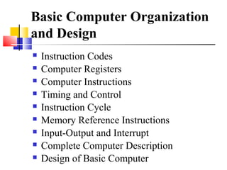
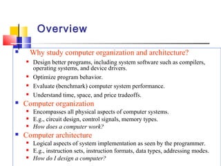
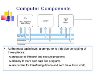
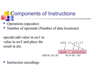
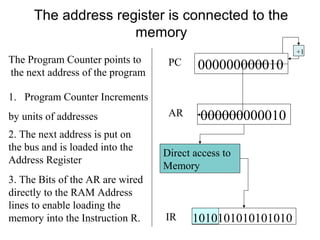
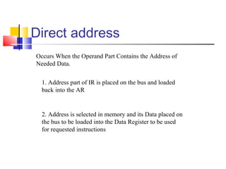
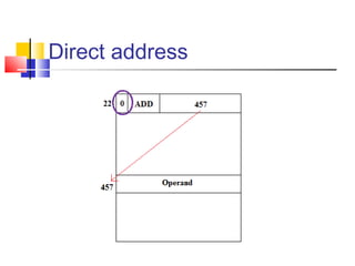
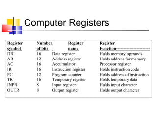
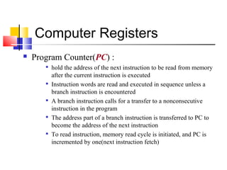
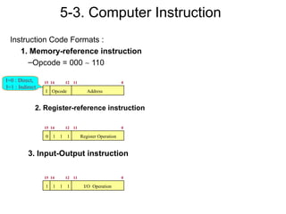
UCS401 Computer System 
Architecture 
Tarunpreet Bhatia 
CSED, Thapar University
Basic Computer Organization 
and Design 
 Instruction Codes 
 Computer Registers 
 Computer Instructions 
 Timing and Control 
 Instruction Cycle 
 Memory Reference Instructions 
 Input-Output and Interrupt 
 Complete Computer Description 
 Design of Basic Computer
Overview 
 Why study computer organization and architecture? 
 Design better programs, including system software such as compilers, 
operating systems, and device drivers. 
 Optimize program behavior. 
 Evaluate (benchmark) computer system performance. 
 Understand time, space, and price tradeoffs. 
 Computer organization 
 Encompasses all physical aspects of computer systems. 
 E.g., circuit design, control signals, memory types. 
 How does a computer work? 
 Computer architecture 
 Logical aspects of system implementation as seen by the programmer. 
 E.g., instruction sets, instruction formats, data types, addressing modes. 
 How do I design a computer?
Computer Components 
• At the most basic level, a computer is a device consisting of 
three pieces: 
A processor to interpret and execute programs 
A memory to store both data and programs 
A mechanism for transferring data to and from the outside world.
Instruction Codes 
A process is controlled by a program 
 A program is a set of instructions that specify 
the operations, data, and the control sequence 
 An instruction is stored in binary code that 
specifies a sequence of microoperations 
 Instruction codes together with data are stored 
in memory (Stored Program Concept).
Program statements and 
computer instructions 
Computer instruction 
Field specifying the 
operation to be executed 
Field specifying the data 
To be operated on
Instruction code format 
 Instruction code format with two parts : Op. 
Code + Address 
 Op. Code : specify 16 possible operations(4 bits) 
 Address : specify the address of an operand(12 bits) 
 If an operation in an instruction code does not need an 
operand from memory, the rest of the bits in the 
instruction(address field) can be used for other purpose 
15 12 11 0 
Op. Code Address 
instruction 
15 12 11 0 
data 
Not an instruction
Components of Instructions 
 Operations (opcodes) 
 Number of operands (Number of data locations) 
opcode:add value in src1 to 
value in src2 and place the 
result in dst. 
ADD R1, R2, R3 R1  R2 + R3 
 Instruction encodings 
add r1,r2,r3 
opcode src1 src2 dst
The address register is connected to the 
memory 
1. Program Counter Increments 
by units of addresses 
PC 0 0 0 0 0 0 0 1 
+1 
000000000010 
2. The next address is put on 
the bus and is loaded into the 
Address Register 
AR 000000000010 
3. The Bits of the AR are wired 
directly to the RAM Address 
lines to enable loading the 
memory into the Instruction R. 
Direct access to 
Memory 
IR 1010101010101010 
The Program Counter points to 
the next address of the program
Direct address 
Occurs When the Operand Part Contains the Address of 
Needed Data. 
1. Address part of IR is placed on the bus and loaded 
back into the AR 
2. Address is selected in memory and its Data placed on 
the bus to be loaded into the Data Register to be used 
for requested instructions
Direct address
Indirect address 
Occurs When the Operand Contains the Address of the Address 
of Needed Data. 
1. Address part of IR is placed on the bus and loaded back 
into the AR 
2. Address is selected in memory and placed on the bus to be 
loaded Back into the AR 
3. New Address is selected in memory and placed on the bus 
to be loaded into the DR to use later
Indirect address
Computer Registers 
Register Number Register Register 
symbol of bits name Function----------------------- 
DR 16 Data register Holds memory operands 
AR 12 Address register Holds address for memory 
AC 16 Accumulator Processor register 
IR 16 Instruction register Holds instruction code 
PC 12 Program counter Holds address of instruction 
TR 16 Temporary register Holds temporary data 
INPR 8 Input register Holds input character 
OUTR 8 Output register Holds output character
Computer Registers 
 Program Counter(PC) : 
 hold the address of the next instruction to be read from memory 
after the current instruction is executed 
 Instruction words are read and executed in sequence unless a 
branch instruction is encountered 
 A branch instruction calls for a transfer to a nonconsecutive 
instruction in the program 
 The address part of a branch instruction is transferred to PC to 
become the address of the next instruction 
 To read instruction, memory read cycle is initiated, and PC is 
incremented by one(next instruction fetch)
5-3. Computer Instruction 
Instruction Code Formats : 
1. Memory-reference instruction 
–Opcode = 000 ~ 110 
I=0 : Direct, 15 14 12 11 0 
I=1 : Indirect 
I Opcode Address 
2. Register-reference instruction 
15 14 12 11 0 
0 1 1 1 Register Operation 
3. Input-Output instruction 
15 14 12 11 0 
1 1 1 1 I/O Operation

Basic computer organization

  • 1.
    UCS401 Computer System Architecture Tarunpreet Bhatia CSED, Thapar University
  • 2.
    Basic Computer Organization and Design  Instruction Codes  Computer Registers  Computer Instructions  Timing and Control  Instruction Cycle  Memory Reference Instructions  Input-Output and Interrupt  Complete Computer Description  Design of Basic Computer
  • 3.
    Overview  Whystudy computer organization and architecture?  Design better programs, including system software such as compilers, operating systems, and device drivers.  Optimize program behavior.  Evaluate (benchmark) computer system performance.  Understand time, space, and price tradeoffs.  Computer organization  Encompasses all physical aspects of computer systems.  E.g., circuit design, control signals, memory types.  How does a computer work?  Computer architecture  Logical aspects of system implementation as seen by the programmer.  E.g., instruction sets, instruction formats, data types, addressing modes.  How do I design a computer?
  • 4.
    Computer Components •At the most basic level, a computer is a device consisting of three pieces: A processor to interpret and execute programs A memory to store both data and programs A mechanism for transferring data to and from the outside world.
  • 5.
    Instruction Codes Aprocess is controlled by a program  A program is a set of instructions that specify the operations, data, and the control sequence  An instruction is stored in binary code that specifies a sequence of microoperations  Instruction codes together with data are stored in memory (Stored Program Concept).
  • 6.
    Program statements and computer instructions Computer instruction Field specifying the operation to be executed Field specifying the data To be operated on
  • 7.
    Instruction code format  Instruction code format with two parts : Op. Code + Address  Op. Code : specify 16 possible operations(4 bits)  Address : specify the address of an operand(12 bits)  If an operation in an instruction code does not need an operand from memory, the rest of the bits in the instruction(address field) can be used for other purpose 15 12 11 0 Op. Code Address instruction 15 12 11 0 data Not an instruction
  • 8.
    Components of Instructions  Operations (opcodes)  Number of operands (Number of data locations) opcode:add value in src1 to value in src2 and place the result in dst. ADD R1, R2, R3 R1  R2 + R3  Instruction encodings add r1,r2,r3 opcode src1 src2 dst
  • 9.
    The address registeris connected to the memory 1. Program Counter Increments by units of addresses PC 0 0 0 0 0 0 0 1 +1 000000000010 2. The next address is put on the bus and is loaded into the Address Register AR 000000000010 3. The Bits of the AR are wired directly to the RAM Address lines to enable loading the memory into the Instruction R. Direct access to Memory IR 1010101010101010 The Program Counter points to the next address of the program
  • 10.
    Direct address OccursWhen the Operand Part Contains the Address of Needed Data. 1. Address part of IR is placed on the bus and loaded back into the AR 2. Address is selected in memory and its Data placed on the bus to be loaded into the Data Register to be used for requested instructions
  • 11.
  • 12.
    Indirect address OccursWhen the Operand Contains the Address of the Address of Needed Data. 1. Address part of IR is placed on the bus and loaded back into the AR 2. Address is selected in memory and placed on the bus to be loaded Back into the AR 3. New Address is selected in memory and placed on the bus to be loaded into the DR to use later
  • 13.
  • 14.
    Computer Registers RegisterNumber Register Register symbol of bits name Function----------------------- DR 16 Data register Holds memory operands AR 12 Address register Holds address for memory AC 16 Accumulator Processor register IR 16 Instruction register Holds instruction code PC 12 Program counter Holds address of instruction TR 16 Temporary register Holds temporary data INPR 8 Input register Holds input character OUTR 8 Output register Holds output character
  • 15.
    Computer Registers Program Counter(PC) :  hold the address of the next instruction to be read from memory after the current instruction is executed  Instruction words are read and executed in sequence unless a branch instruction is encountered  A branch instruction calls for a transfer to a nonconsecutive instruction in the program  The address part of a branch instruction is transferred to PC to become the address of the next instruction  To read instruction, memory read cycle is initiated, and PC is incremented by one(next instruction fetch)
  • 16.
    5-3. Computer Instruction Instruction Code Formats : 1. Memory-reference instruction –Opcode = 000 ~ 110 I=0 : Direct, 15 14 12 11 0 I=1 : Indirect I Opcode Address 2. Register-reference instruction 15 14 12 11 0 0 1 1 1 Register Operation 3. Input-Output instruction 15 14 12 11 0 1 1 1 1 I/O Operation