Downloaded 1,142 times
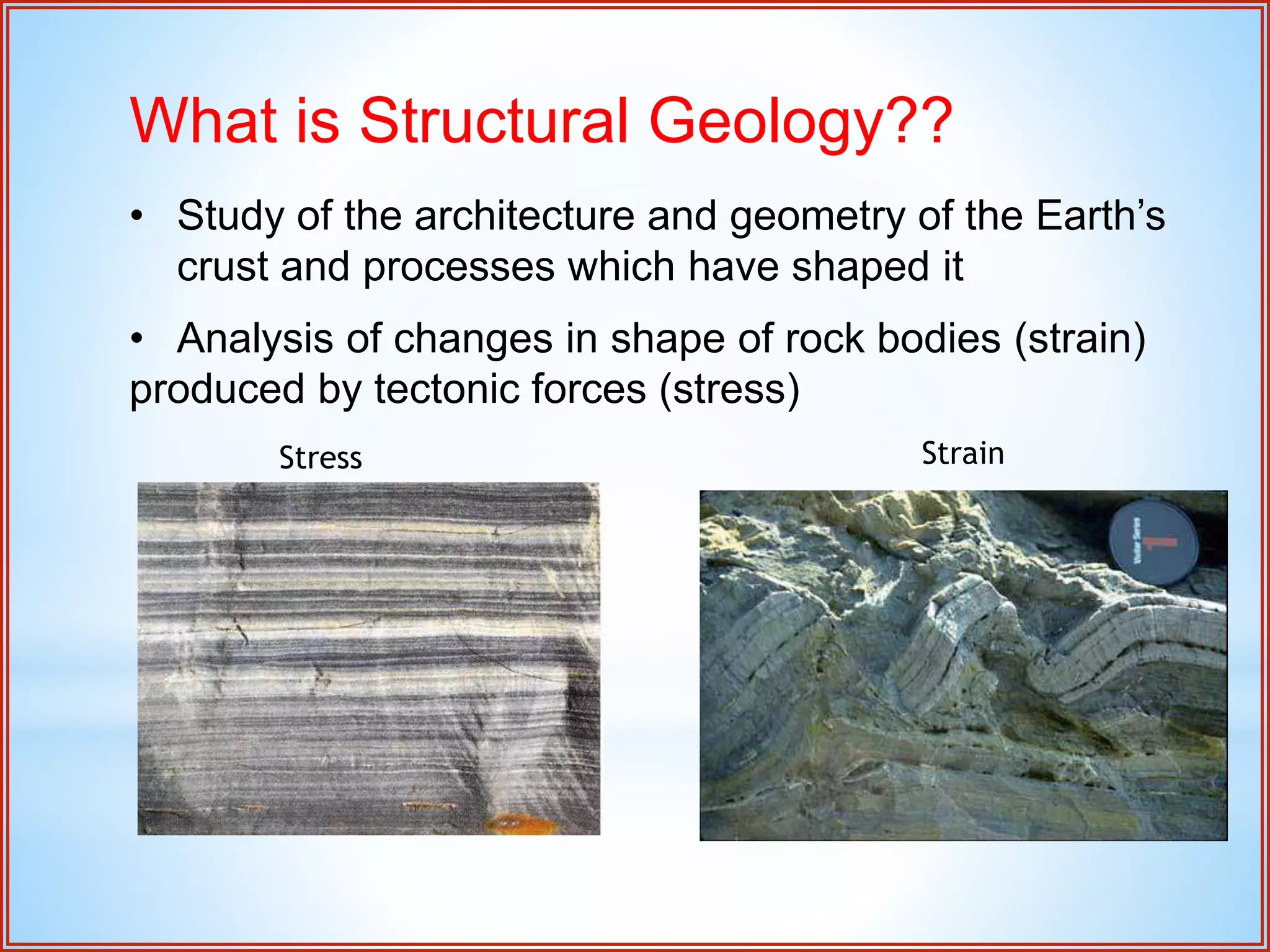
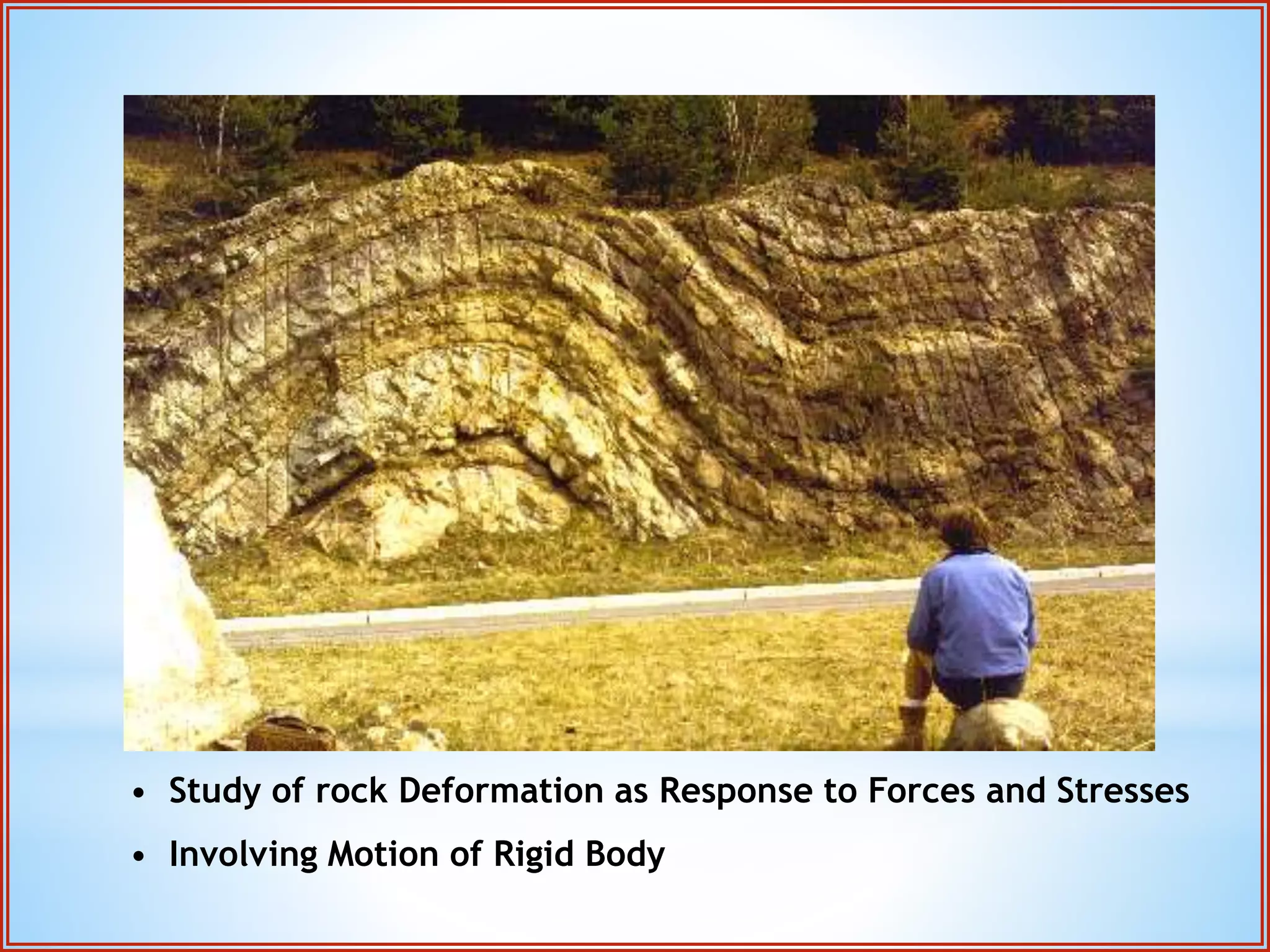
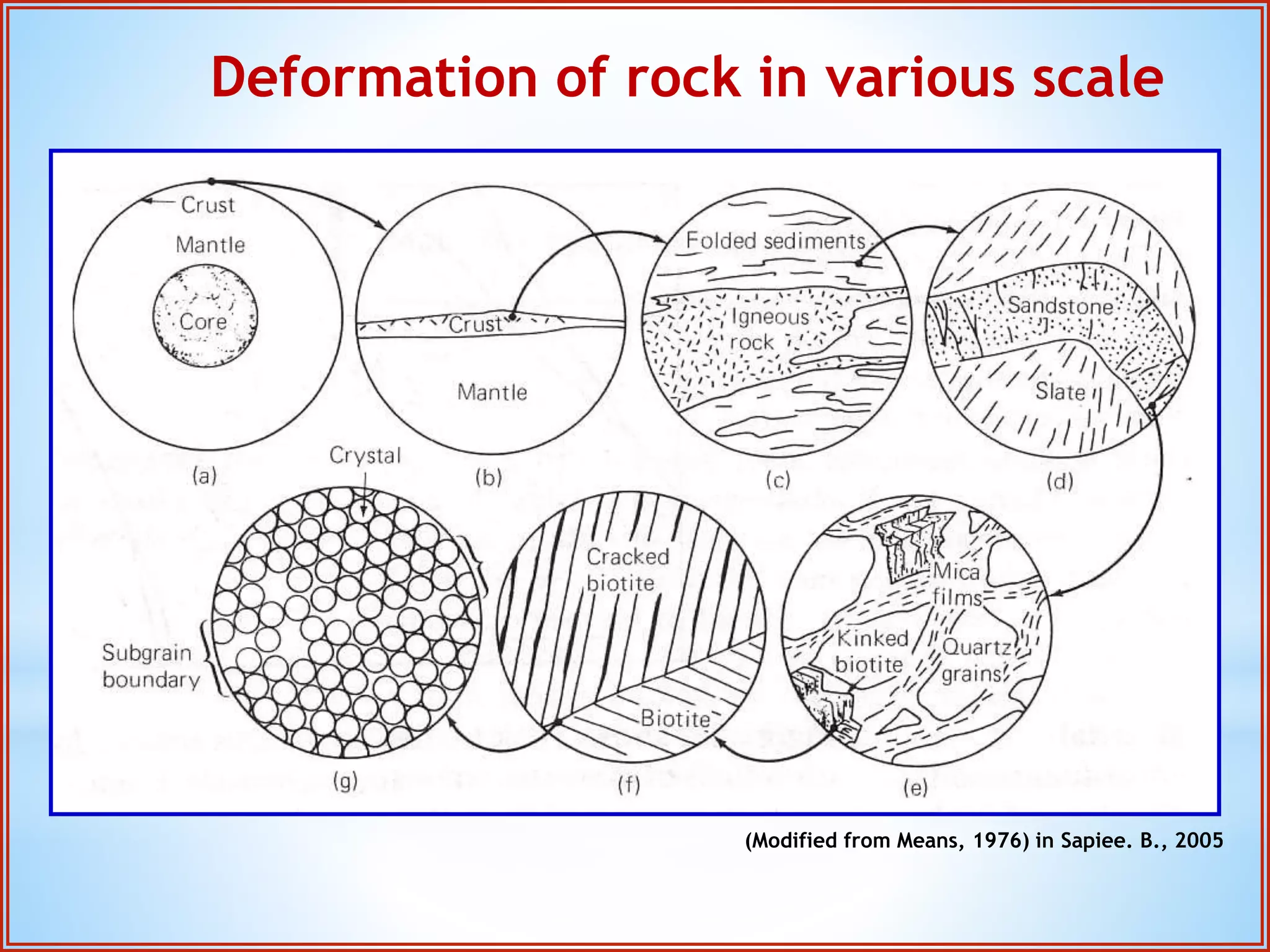
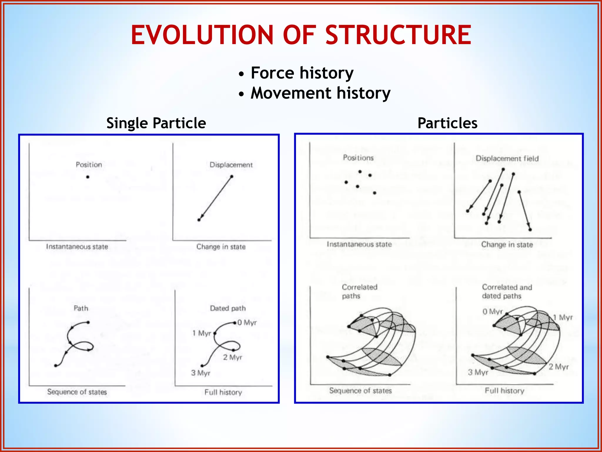
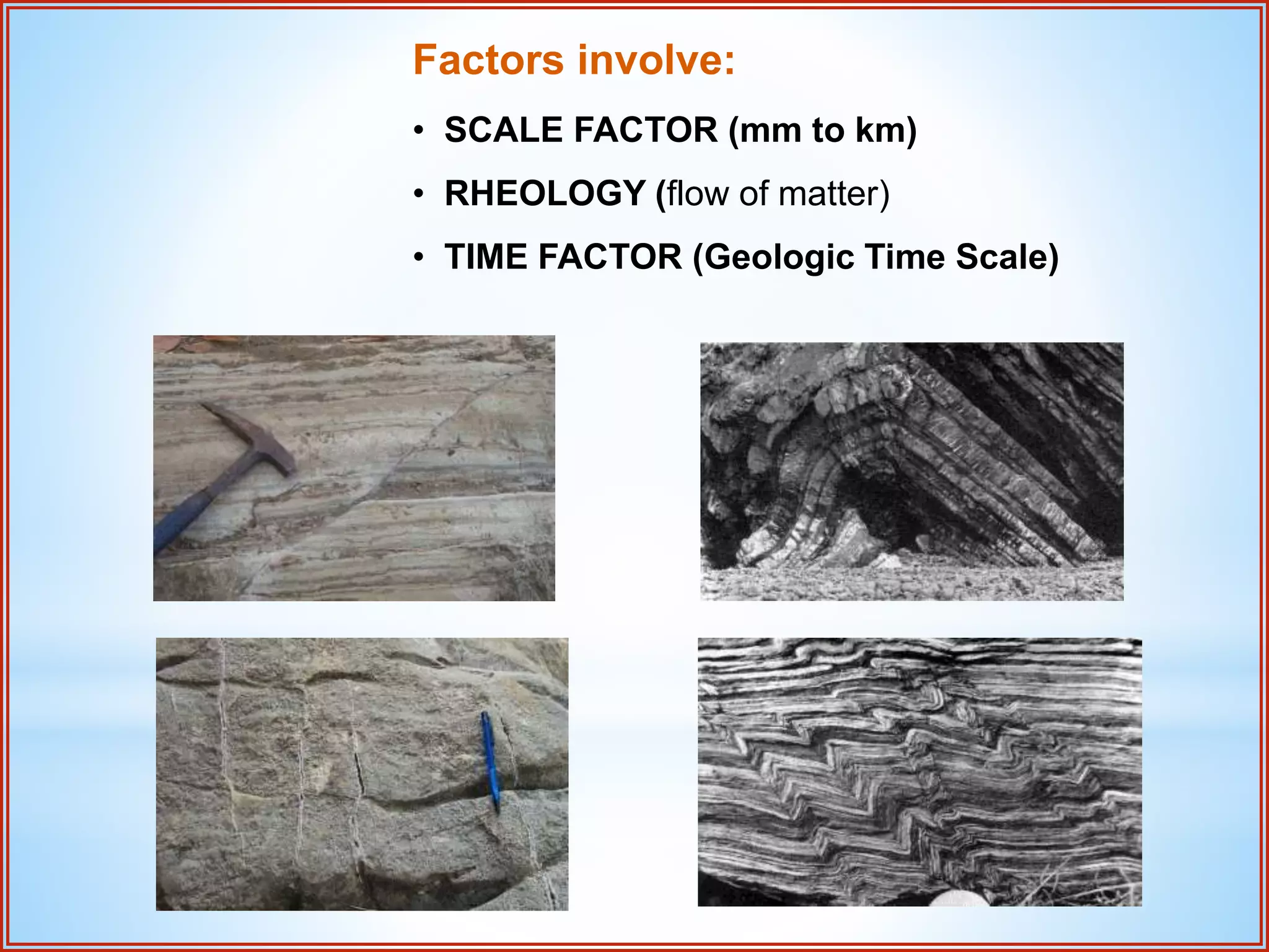
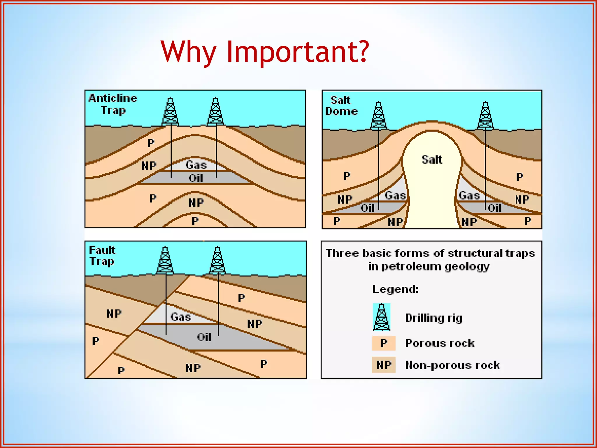
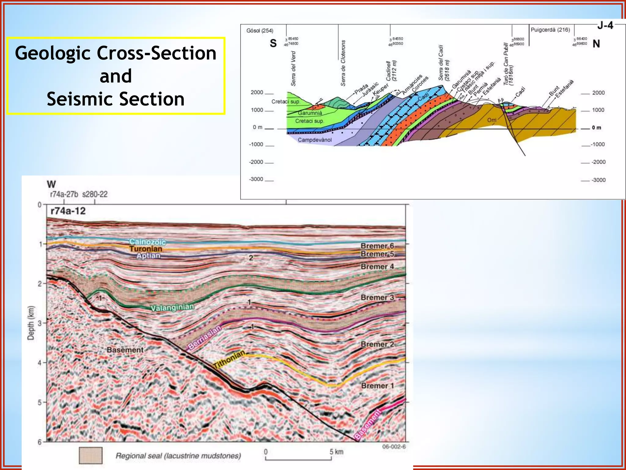
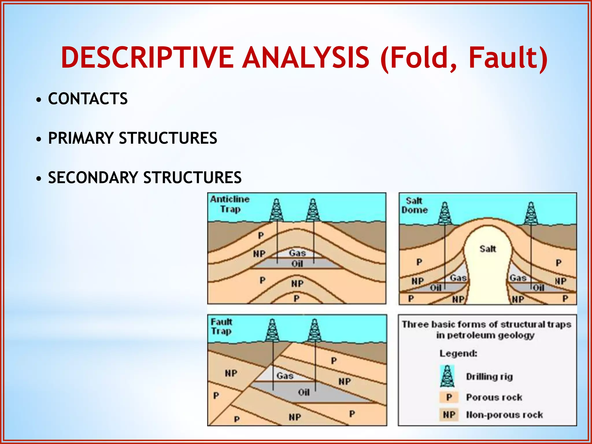
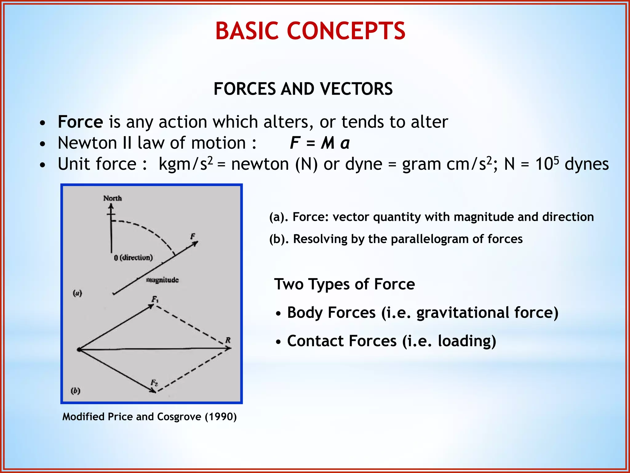
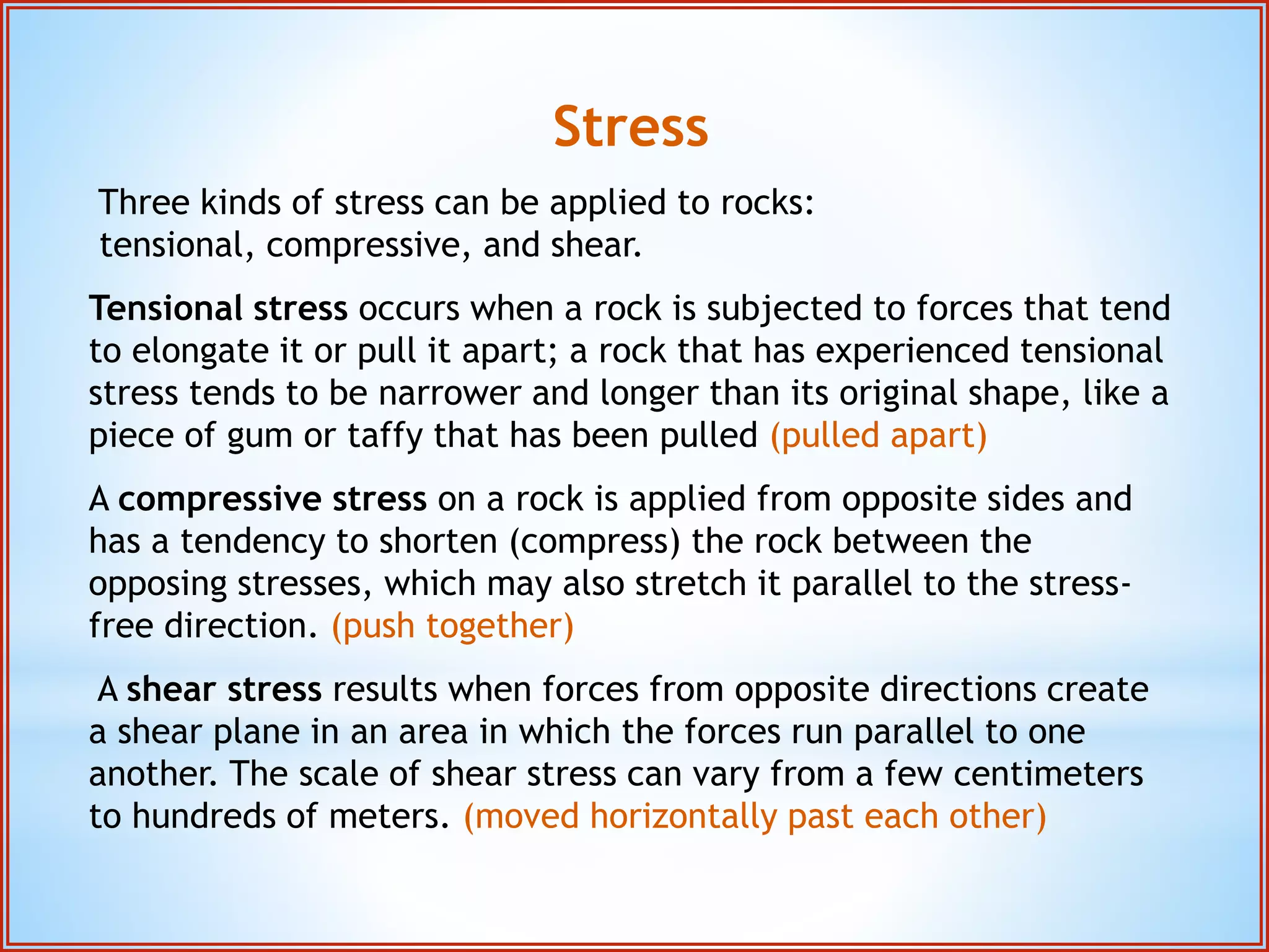
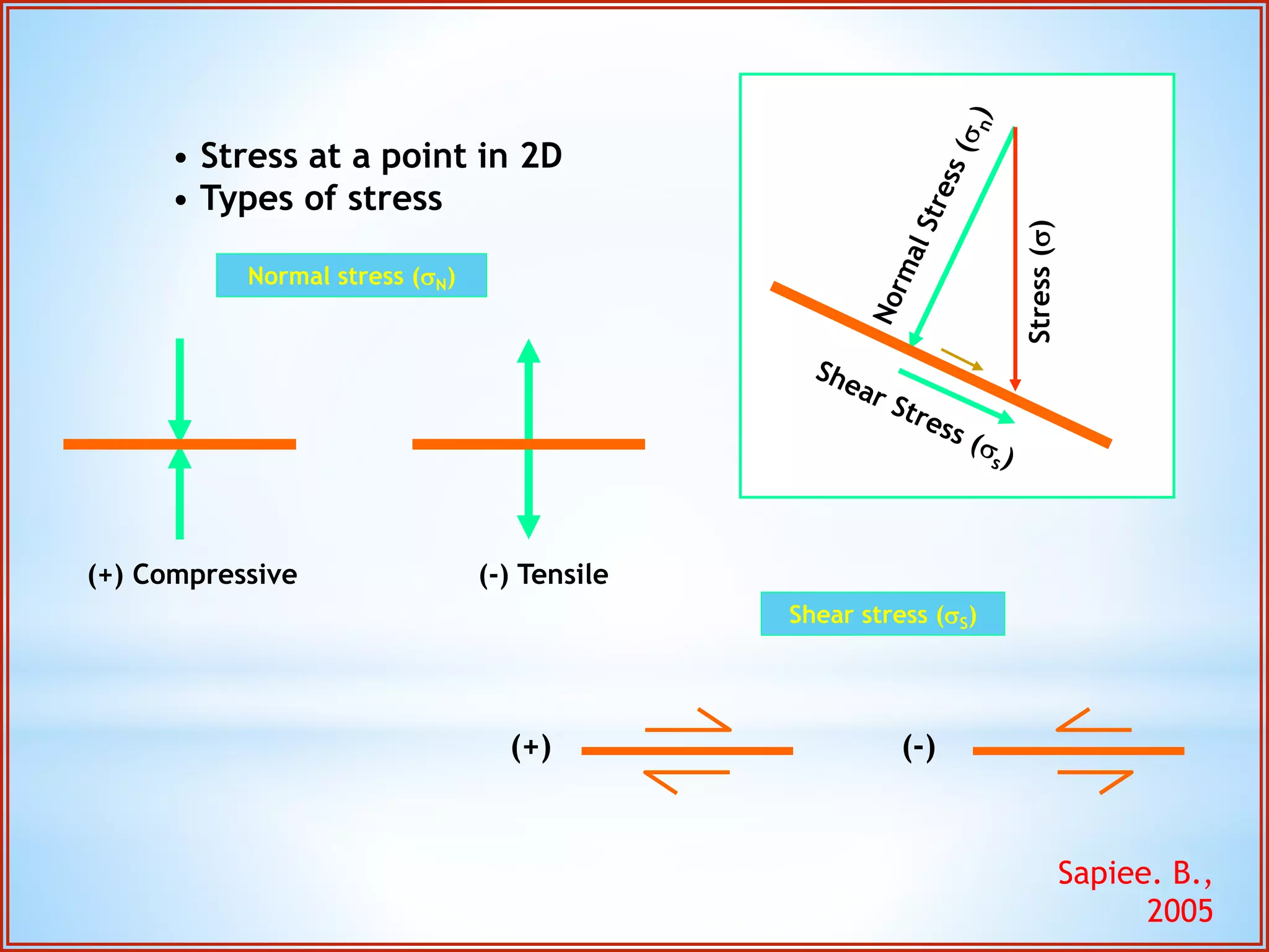
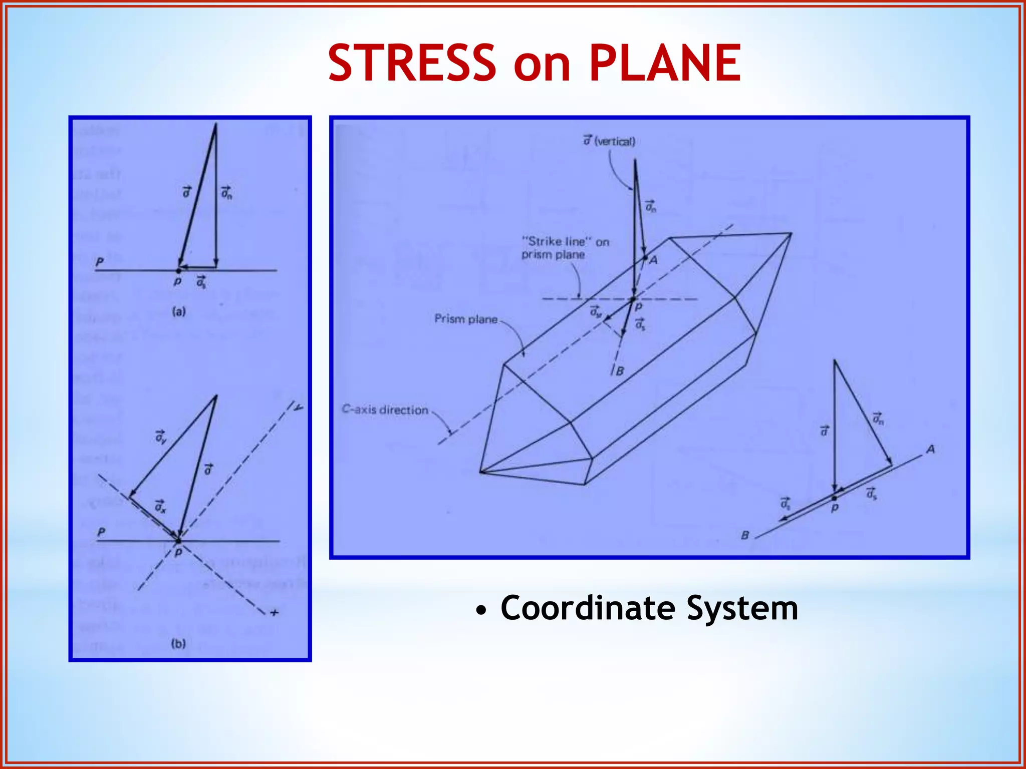
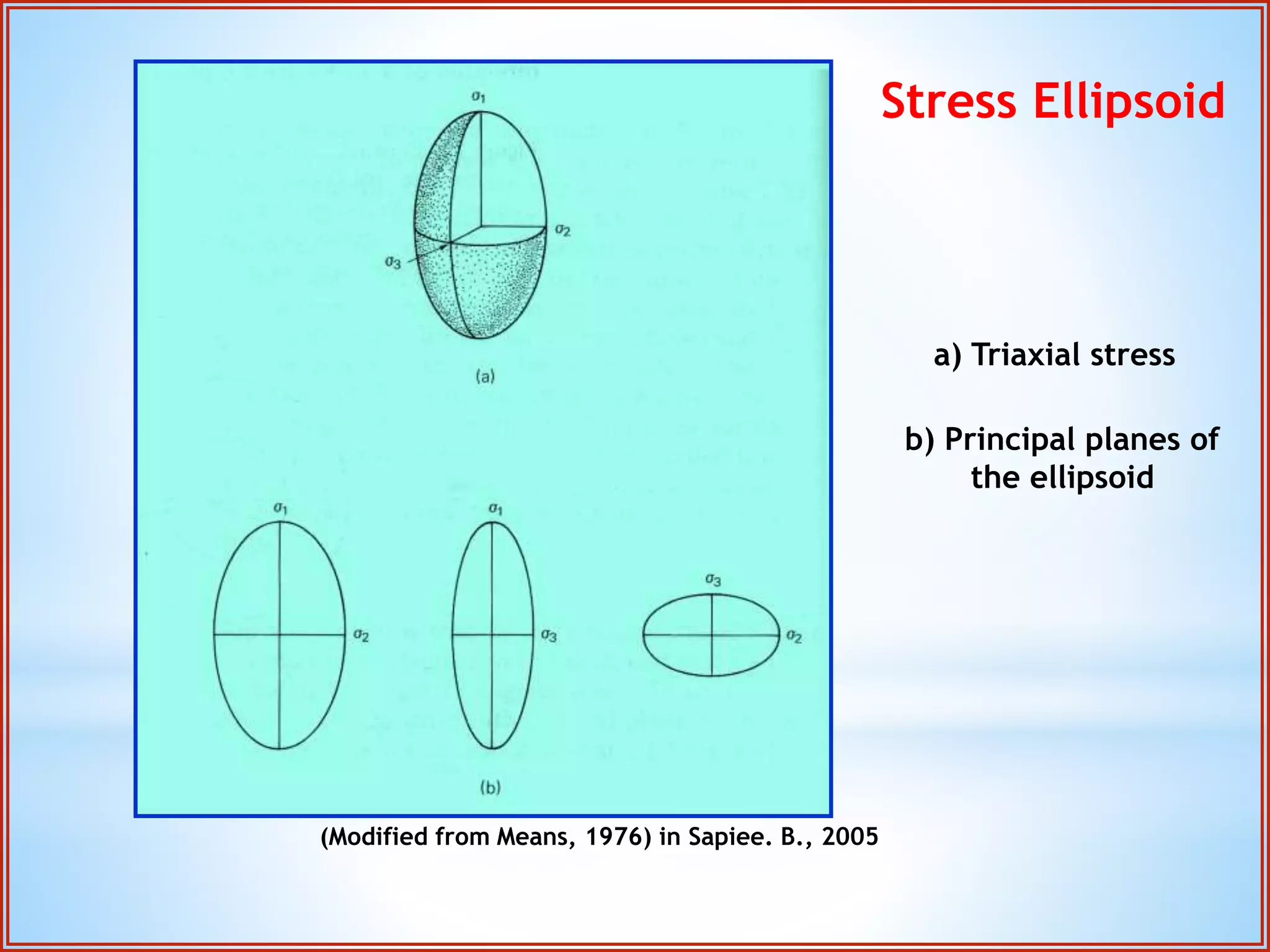
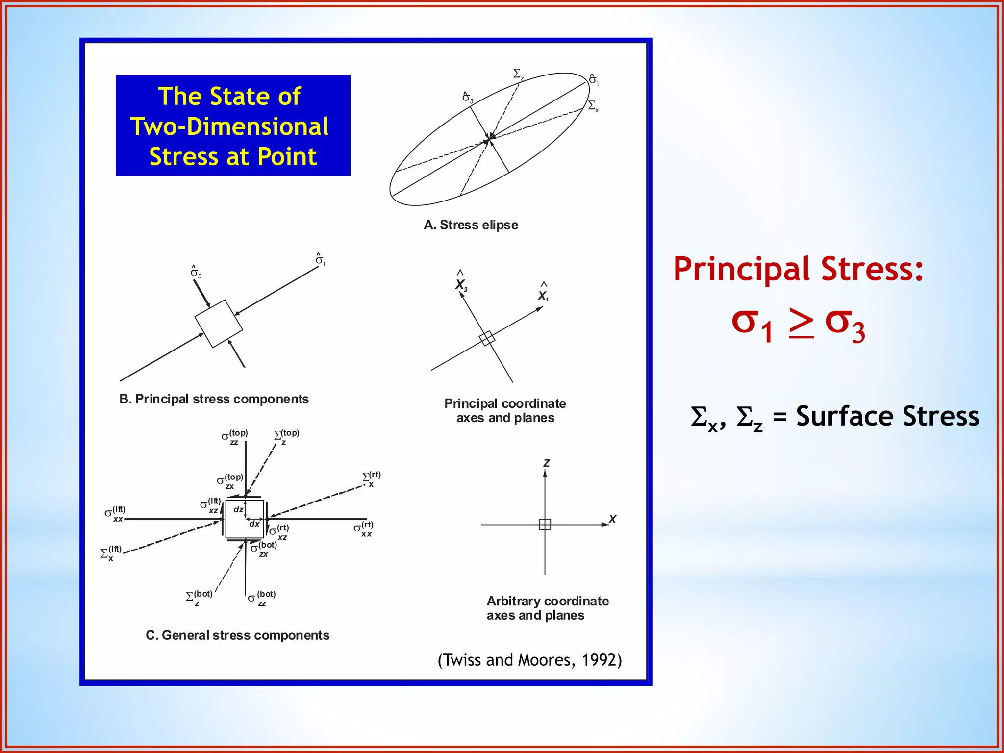
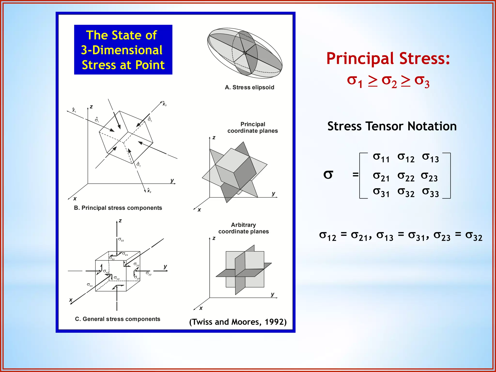
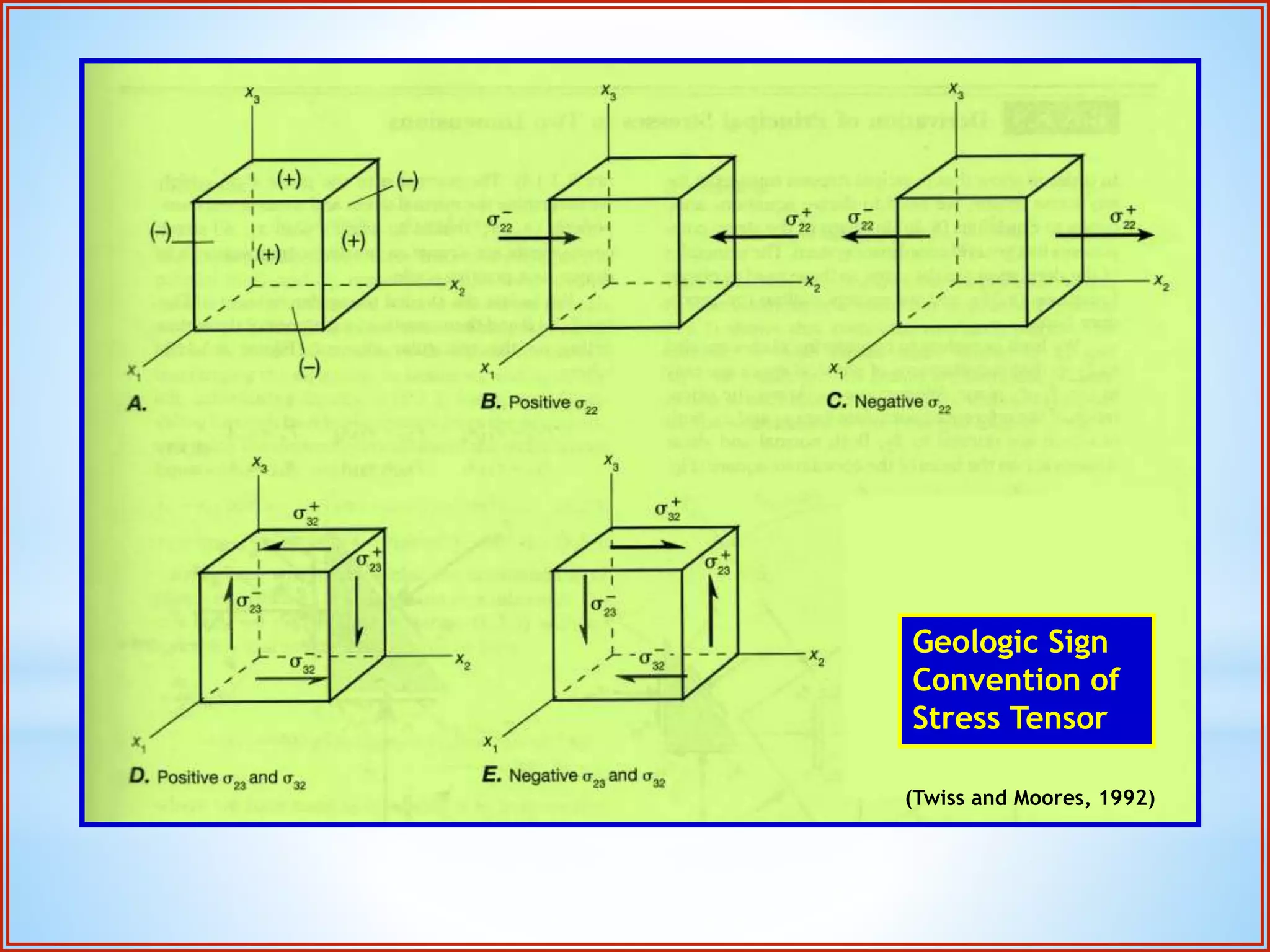
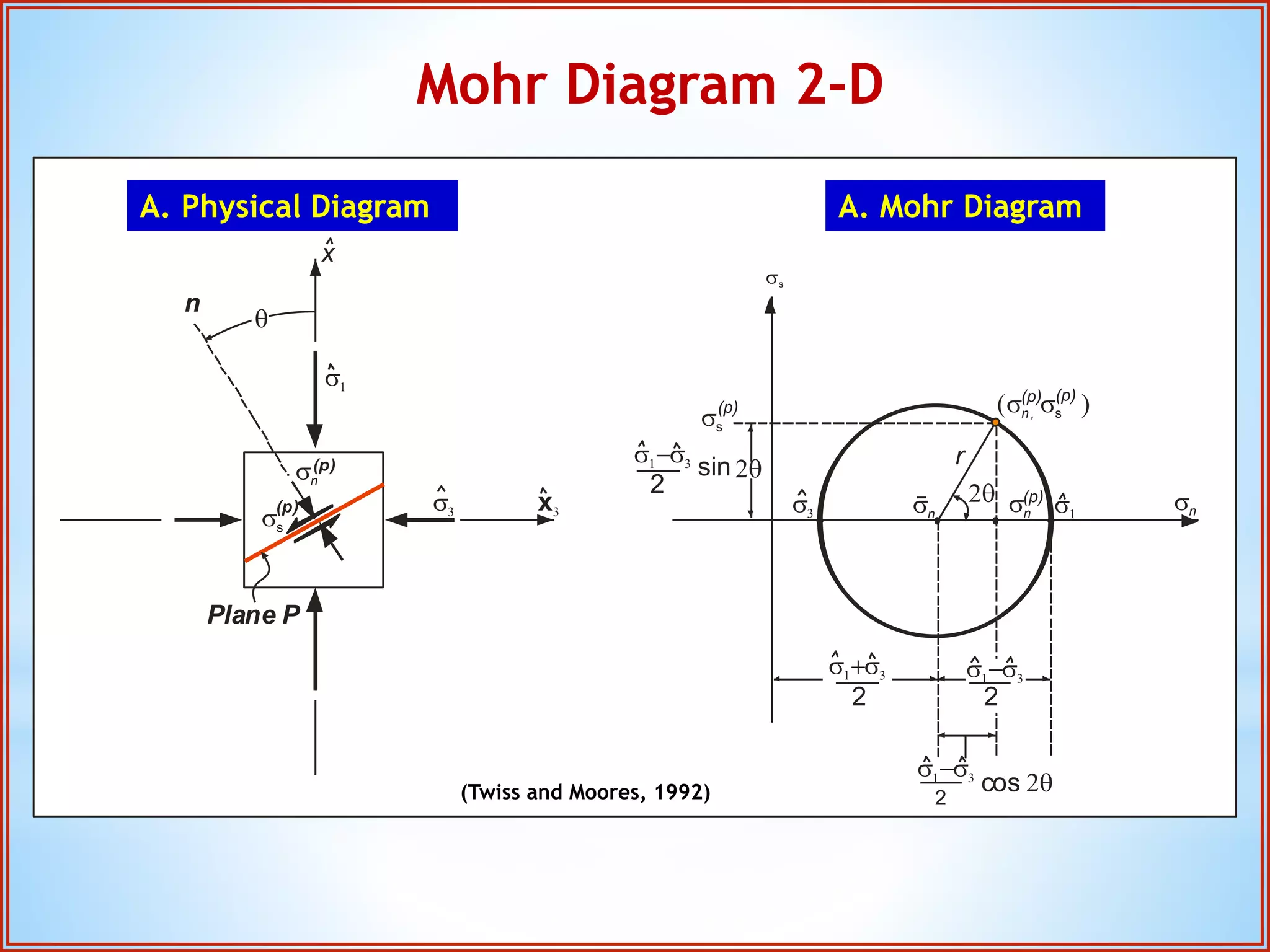
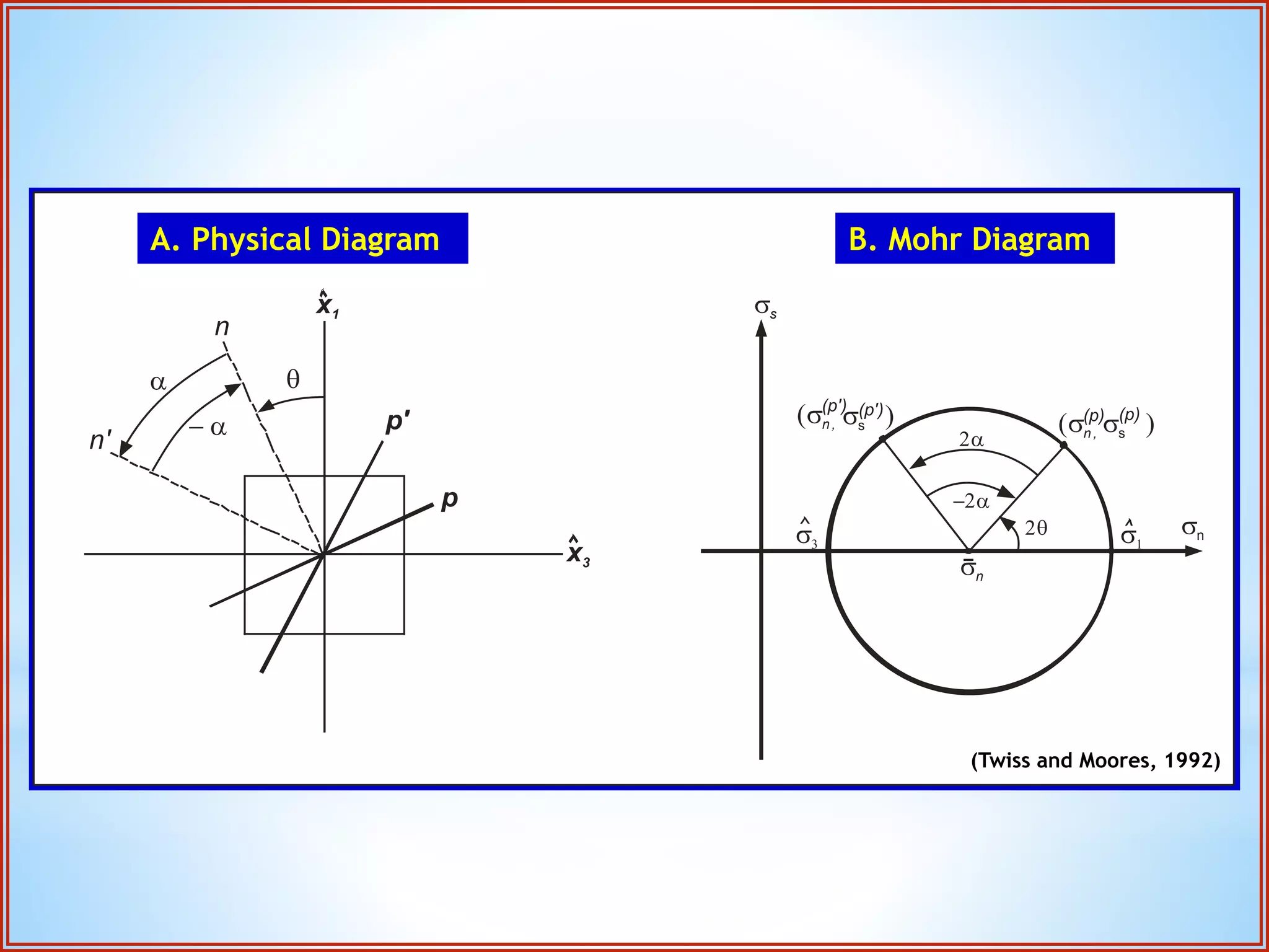
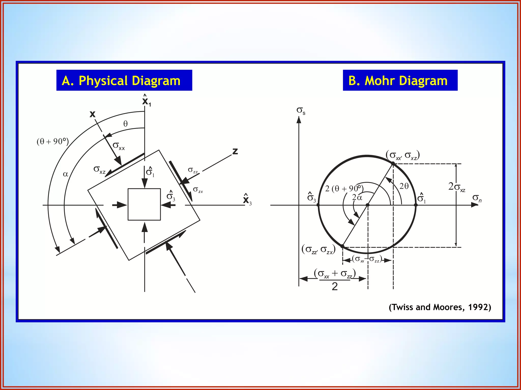
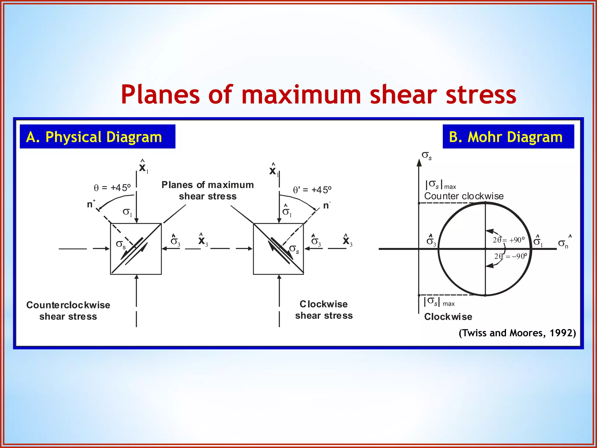
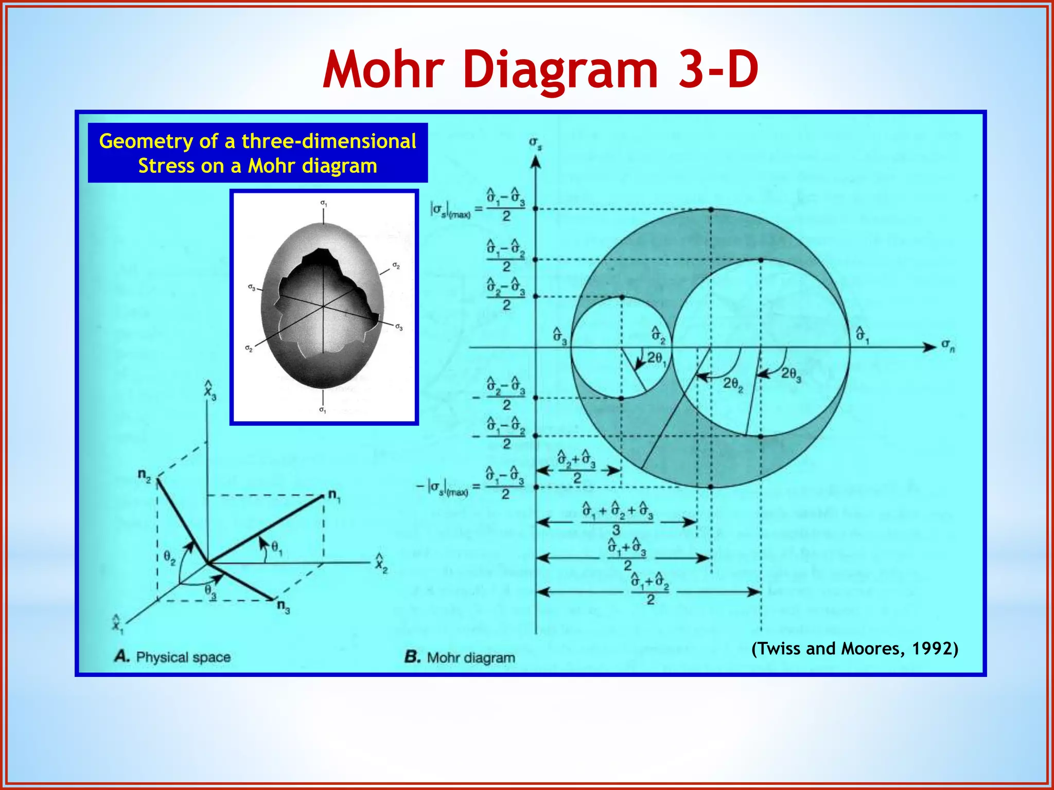
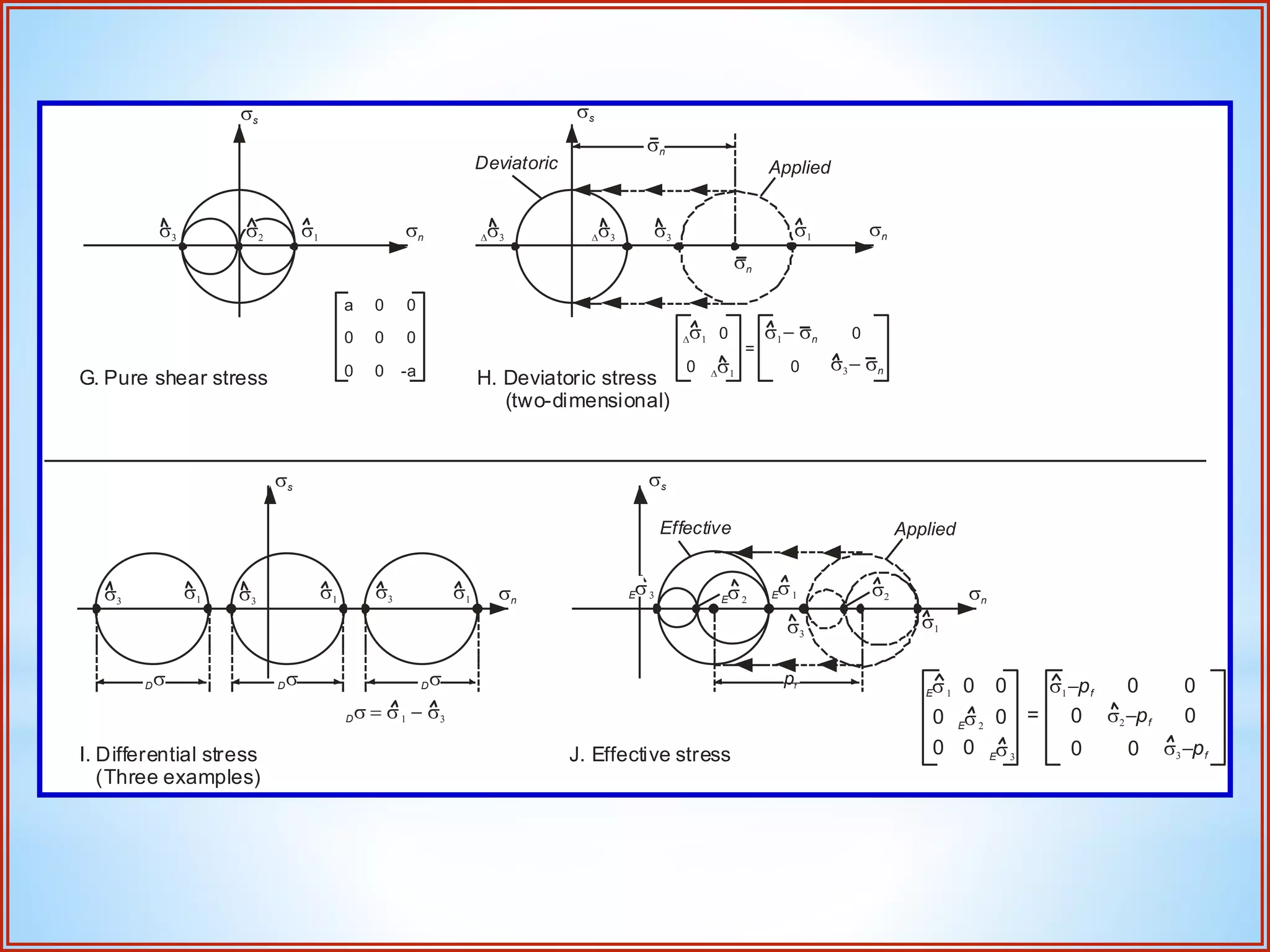
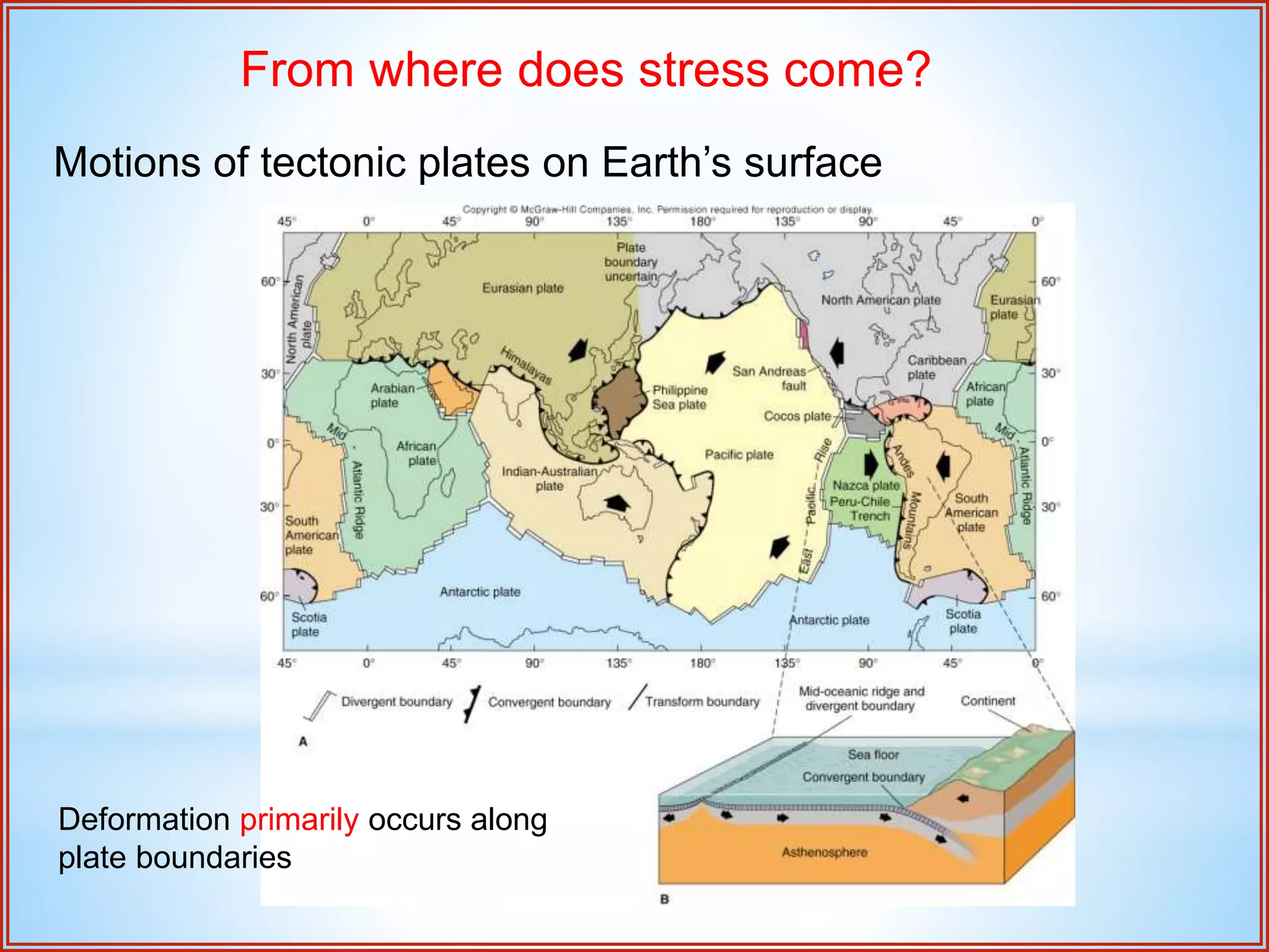
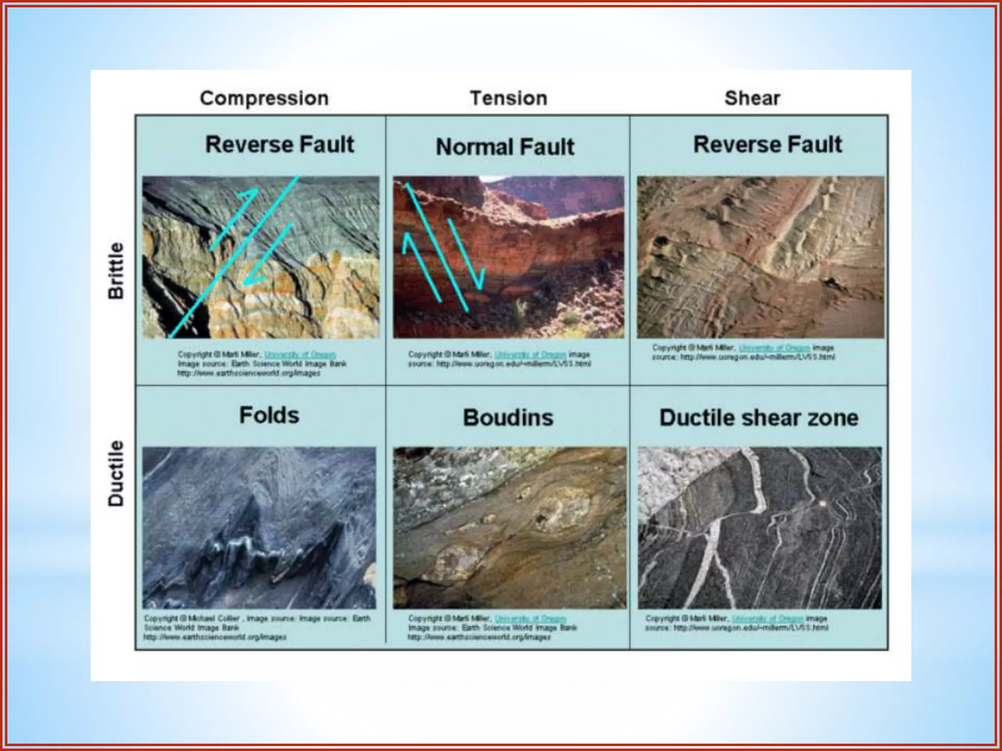
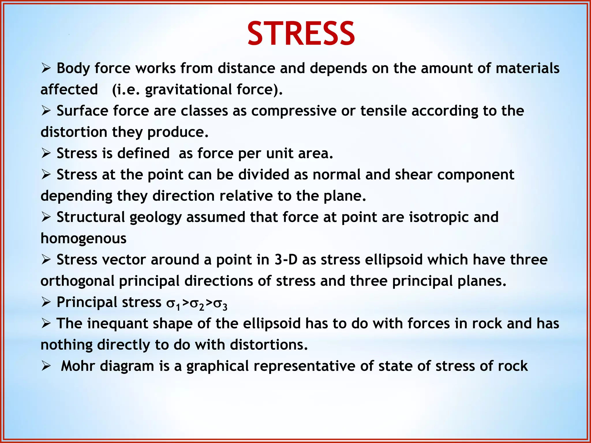


Structural geology is the study of the architecture and geometry of the Earth's crust and the processes that have shaped it. It involves analyzing how rock bodies deform in response to tectonic stresses. Structural analysis generally involves descriptive, kinematic, and dynamic analysis. Descriptive analysis describes rock structures like folds and faults. Kinematic analysis evaluates strain and changes in shape and orientation of rocks. Dynamic analysis reconstructs the stresses that caused rock deformation and failure. Stresses in rocks can be tensile, compressive, or shear stresses. Stress is analyzed using concepts like the stress tensor, Mohr's circle diagrams, and the orientation of maximum shear stresses. The main sources of stress that drive deformation are the motions of tectonic


