Downloaded 188 times
![Typical UTRA-FDD uplink data rates 4 8 16 64 Spreading 15 15 15 15 DPCCH [kbit/s] 960 480 240 60 DPDCH [kbit/s] 384 144 64 12.2 (voice) User data rate [kbit/s]](https://image.slidesharecdn.com/lecture-10-090614085703-phpapp02/85/Lecture-10-24-320.jpg)

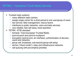
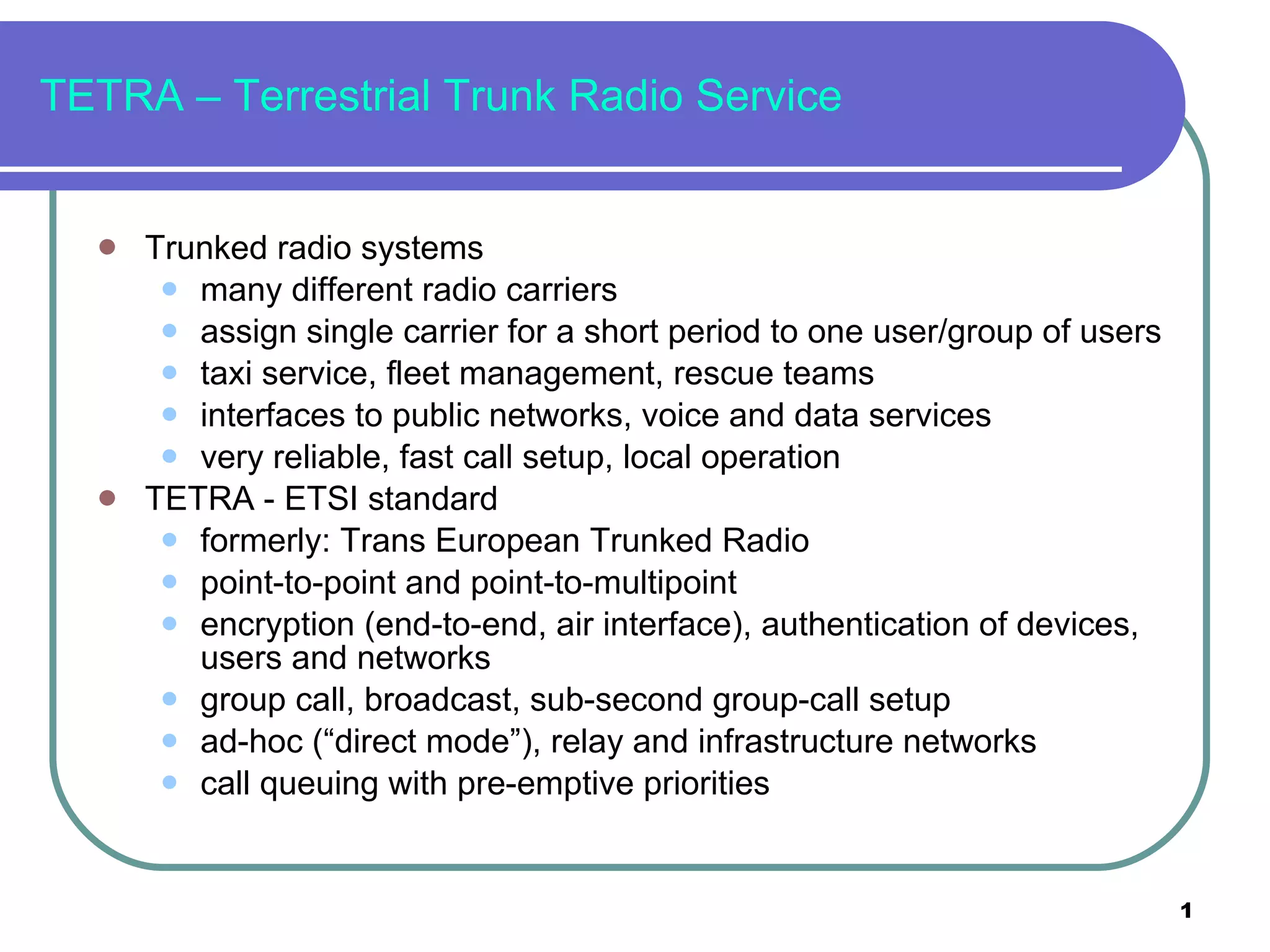
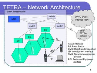
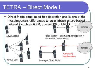
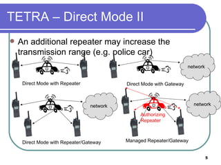
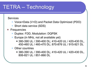
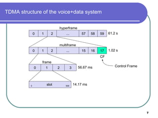
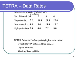
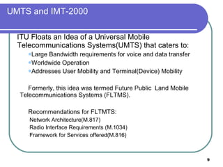
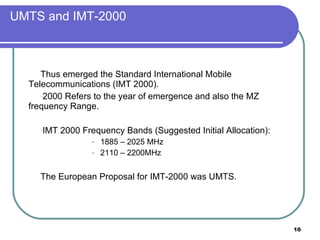
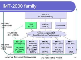
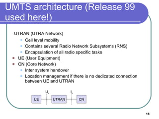
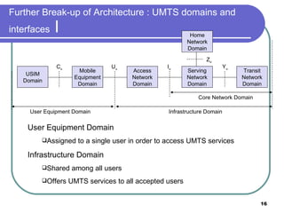
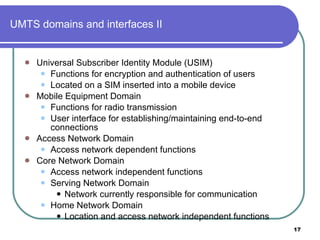
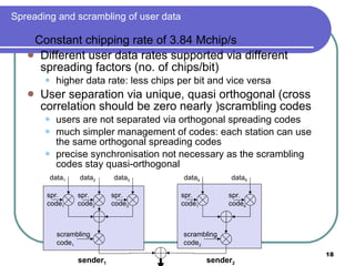
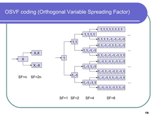
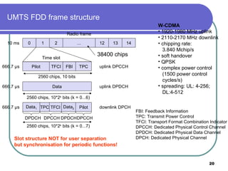
TETRA is a trunked radio standard used in public safety networks. It allows for fast call setup, voice and data services, and operates in both infrastructure and ad-hoc modes. UMTS is the 3G cellular standard developed by ETSI for wide-area mobile communication. It uses W-CDMA technology and supports high data rates through variable spreading factors and orthogonal codes. UMTS has an architecture with domains for the user equipment, access network, core network and home network connected by defined interfaces.