Downloaded 10 times

![2
(GSM900, GSM–railway [GSM–R], GSM1800, GSM1900, and
GSM400), supporting some 250 million of the world’s 450 million cellular subscribers
with international roaming in approximately 140 countries and 400 networks.
2G to 3G: GSM Evolution
Phase 1 of the standardization of GSM900 was completed by the European
Telecommunications Standards Institute (ETSI) in 1990 and included all necessary
definitions for the GSM network operations. Several tele -services and bearer services have
been defined (including data transmission up to 9.6 kbps), but only some very basic
supplementary services were offered. As a result, GSM standards were enhanced in Phase
2 (1995) to incorporate a large variety of supplementary services that were comparable to
digital fixed network integrated services digital network (ISDN) standards. In 1996, ETSI
decided to further enhance GSM in annual Phase 2+ releases that incorporate 3G
capabilities.
GSM Phase 2+ releases have introduced important 3G features such as intelligent network
(IN) services with customized application for mobile enhanced logic (CAMEL), enhanced
speech compression/decompression (CODEC), enhanced full rate (EFR), and adaptive multi-
rate (AMR), high–data rate services and new transmission principles with high-speed circuit-
switched data (HSCSD), general packet radio service (GPRS), and enhanced data rates for
GSM evolution (EDGE). UMTS is a 3G GSM successor standard that is downward-
compatible with GSM, using the GSM Phase 2+ enhanced core network.
1.4.1 IMT–2000
The main characteristics of 3G systems, known collectively as IMT–2000, are a
single family of compatible standards that have the following characteristics:
1. Used worldwide
2. Used for all mobile applications
3. Support both packet-switched (PS) and circuit-switched (CS) data transmission
4. Offer high data rates up to 2 Mbps (depending on mobility/velocity)
5. Offer high spectrum efficiency](https://image.slidesharecdn.com/finalreport-150330082129-conversion-gate01/85/3G-report-file-2-320.jpg)

![4
communication–136 [UWC– 136]/EDGE) as TDMA–based
enhancements to D–AMPS/GSM—all of which are leading
previous standards toward the ultimate goal of IMT–2000.
The figure 2 show the shift from 1G to 3G
igure 2: Evolution from 1G to 3G](https://image.slidesharecdn.com/finalreport-150330082129-conversion-gate01/85/3G-report-file-4-320.jpg)


![12
HN HN
H 2 N =
HN HN Where
HN contains the same but inverted elements of HN .
Rule of Thumb: For generating the matrix is for a given seed repeat it over right once and
below once and invert diagonally as shown in the above example. For the given seed
Therefore, to derive a set of four orthogonal Walsh sequences w0, w1, w2, and
w3, we only need to generate a Hadamard matrix of order 4, or
The four orthogonal sequences in this Walsh code set are taken from the rows of the
matrix H4; that is,
W
0 = [0 0 0 0]
W 1 = [01 0 1]
W
2 = [0 0 1 1]
W
3 = [0 1 1 0]
For DS-SS multiple access, three conditions that must be met by a set of orthogonal
sequences. The three conditions are as follows:
1. The cross-correlation should be zero or very small.
2. Each sequence in the set has an equal number of 1s and -1s, or the number of 1s
differs from the number of -1s by at most one.
3. The scaled dot product of each code should equal to 1.
By changing the 0s to -1s and keeping the 1s as it is in each of the four sequences above,
that is,
W 0 = [−1−1 −1 −1]
W 1 = [+ 1 +1 −1 −1]
W 2 = [− 1−1 +1 +1]
W 3 = [− 1+1 +1 −1]](https://image.slidesharecdn.com/finalreport-150330082129-conversion-gate01/85/3G-report-file-12-320.jpg)

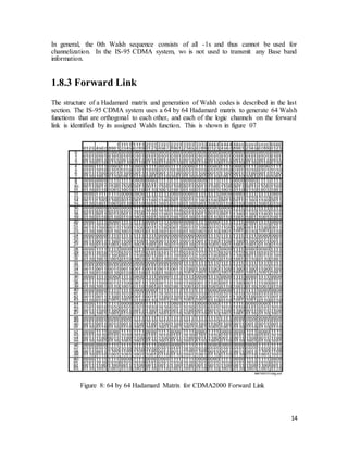

![16
1.8.4 Channelization
Channelization is done in following steps
• Generate Walsh Codes
• Generate Codes for each message
• Transmitted Signal
• Retrieval of message
Suppose that there are three different users, and each user wishes to send a separate
message. The separate messages are:
M 0 = [+1 −1 +1]
M 1 = [+ 1 +1 −1]
M 2 = [− 1 +1 +1]
There respective codes are as follows:
W 0 = [−1 −1 −1 −1]
W 1 = [+ 1 +1 −1 −1]
W 2 = [− 1 −1 +1 +1]
W 3 = [− 1 +1 +1 −1]
The signal to be transmitted is calculated to be m (t) * w (t). This is shown below:
M1 (t) = +1 -1 +1
M1 (t) = +1 +1 +1 +1 -1 -1 -1 -1 +1 +1 +1 +1
M1 (t) = -1 +1 -1 +1 -1 +1 -1 +1 -1 +1 -1 +1
M
1 (t) * W1 (t) = -1 +1 -1 +1 +1 -1 +1 -1 -1 +1 -1 +1
Similarly for the M2 (t) and M3 (t)
M2 (t) * W2 (t) = -1 -1 +1 +1 -1 -1 +1 +1 +1 +1 -1 -1
M3 (t) * W3 (t) = +1 -1 -1 +1 -1 +1 +1 -1 -1 +1 +1 -1
The spread-spectrum signals for all three messages, m1(t)w1(t), m2(t)w2(t), and
m3(t)w3(t), are combined to form a composite signal C(t); that is,
C (t) = M1 (t) * W1 (t) + M2 (t) * W2 (t) + M3 (t) * W3 (t)
The resulting C (t) is
C (t) = -1 -1 -1 +3 -1 -1 +3 -1 -1 +3 -1 -1](https://image.slidesharecdn.com/finalreport-150330082129-conversion-gate01/85/3G-report-file-16-320.jpg)


![21
At the bit level, the sync channel is transmitted in groups of sync channel superframes; each
superframe contains 96 bits and lasts 90 ms, yielding a data rate of (96 bits/90 ms) = 1,200 bps.
Each superframe contains three sync channel frames of equal length and duration (see Figure
10). Each sync channel frame is aligned with the short PN sequence associated with the
transmitting sector. Note that the short PN sequence repeats every 26.67 ms, and each period
of the short PN sequence is synchronized with each sync channel frame. Therefore, once the
mobile acquires synchronization with the pilot channel, the alignment for the sync channel is
immediately known. This is because the sync channel is spread with the same pilot PN
sequence, and because the frame timing of the sync channel is aligned with that of the pilot PN
sequence [1] – see figure 9. Once the mobile achieves alignment with the sync channel, the
mobile can start reading the sync channel message.
Figure 10: Sync Channel
Figure 11: Sync Channel Frame](https://image.slidesharecdn.com/finalreport-150330082129-conversion-gate01/85/3G-report-file-21-320.jpg)


![27
CHAPTER-3
RESEARCH UNDERGOING IN SPECIFIED AREA
3.1 Optical Fiber Communication using CDMA
This is related to the use of CMDA concepts in optical fiber communications. A non-
coherent synchronous optical fiber code-division multiple-access (CDMA) network is
proposed. In this network, sequence-inversion keying (SIK) of intensity modulated
unipolar balanced Walsh code sequences is employed, whereby a code sequence is
transmitted for each data ‘1’ bit while the logical complement of that sequence is
transmitted for each data ‘0’ bit. At the receiver the received optical signal is correlated
with the bipolar form of the reference sequence. Since the code sequences are balanced and
the unipolar-bipolar correlation is implemented the same correlation functions as a bipolar
system can be obtained. Hence, in the proposed synchronous optical fiber CDMA network,
the cross-correlation of the address sequence and the undesired sequences is zero, that is,
the interference is completely eliminated. Therefore, a very large number of users can
transmit at the same time and very high throughput can be achieved. The novel design of
programmable transmitter and receiver for non -coherent synchronous optical fiber CDMA
networks using balanced Walsh codes is also presented. The transmitter and receiver are
designed based on the use of electro-optical switches and optical delay-lines. This idea is
discussed in [1]
3.2 Difference between WCDMA with CDMA2000
With the introduction of the third generation systems (IMT-2000), second generation
capabilities (voice and low/medium rate data) are extended adding multimedia capabilities
to second-generation platforms such as support for high bit rates and introduction of
packet data/IP access. In this paper the technical features of the two IMT-2000 radio
interface proposals, ARIB/ETSI’s WCDMA and TIA’s cdma2000, are discussed and a
comparison is being made regarding their performances.
After the similarities are given briefly, the study is more focused on the differences that
are affecting the performance. Main issues of the differences are examined in detail to
find out the benefits or the drawbacks that those issues bring to each proposal. This is
discussed in details in [2].
Some other research papers are also read during the ES2006 discussed in [3], [4], [5]](https://image.slidesharecdn.com/finalreport-150330082129-conversion-gate01/85/3G-report-file-27-320.jpg)
![28
References
Reference ResearchPapers
[1] “Synchronous Optical Fiber Code Division Multiple Access Networks Using
Walsh Code” by Pham Manh Lam and Keattisak Sripimanwatt – IEEE 7th Int.
Symp. on Spread Spectrum Tech & Appl., Prague, Czech Republic, Sept 2-5,
2002
[2] “Downlink Admission/Congestion Control and Maximal Load in CDMA
Networks” By Fran¸cois Baccelli, Bartłomiej Błaszczyszyn & Florent Tournois -
0018-9545/02$17.00 © 2002 IEEE
[3] “Capacity Reduction of WCDMA Downlink in the Presence of Interference
from Adjacent Narrow-Band System” by Kari Heiska, Harri Posti, Peter
Muszynski, Pauli Aikio, Jussi Numminen, and Miikka Hämäläinen – 0018-
9545/02$17.00 © 2002 IEEE
[4] “A Comparison Study of 3G System Protocols: CDMA2000 VS. WCDMA” by
Emre A. Yavuz and Dr. Victor Leung
[5] “Load Balancing in WCDMA Systems by Adjusting Pilot Power” by Nagaike,
R. Harmen, S. Nokia Res
Reference URLs
1. http://www.radio-
electronics.com/info/cellulartelecomms/cellular_concepts/cellular_concept.php
2. http://www.umtsworld.com/technology/cdma2000.htm
3. http://www.radio-
electronics.com/info/cellulartelecomms/cdma-
sys/cdmaintro/cdmaintro.php
4. http://www.mobiledia.com/glossary/17.html
5. http://www.sss-mag.com/ss.html#tutorial
6. http://www.umtsworld.com/technology/cdma2000.htm
7. http://www.umtsworld.com/technology/wcdma.htm
Reference Books
13. “CDMA RF System Engineering” by Samuel C. Yang
14. “CDMA System Engineering Hand Book” by Jhong Sam Lee and Leonard E.
Miller
15. “Digital Communication over Fading Channels” by Marvin K. Simon and
Mohamed-Slim Alouini
16. “TDD-CDMA for Wireless Communications” by Riaz Esmailzadeh and Masao
Naka- gawa](https://image.slidesharecdn.com/finalreport-150330082129-conversion-gate01/85/3G-report-file-28-320.jpg)

This document provides an overview of 3G mobile communication networks and the evolution from 1G to 3G systems. It discusses the background and early stages of 1G analog cellular networks, the development of 2G digital cellular networks, and the standardization of 3G networks through IMT-2000. It then focuses on CDMA2000, describing it as an evolutionary step from CDMAOne that is compatible with 2G networks and approved as an IMT-2000 3G standard, with data rates up to 2Mbps. Key concepts like forward/reverse links and duplexing methods like time division and frequency division duplex are also introduced.


