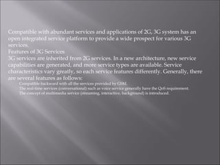
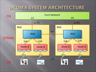
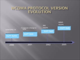
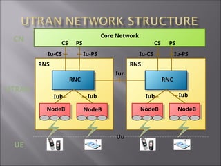
1. CDMA Principle
2. 3G Overview
3. WCDMA Fundamental
Multiple Access Technology
Frequency division multiple access (FDMA)
Time division multiple access (TDMA)
Code division multiple access (CDMA)
frequency
time
power
FDMA
frequency
time
power
TDMA
power
time
CDMA
frequency
1-Frequency Division Multiple Access means dividing the whole available spectrum
into many single radio channels (transmit/receive carrier pair). Each channel can
transmit one-way voice or control information. Analog cellular system is a typical
example of FDMA structure.
2-Time Division Multiple Access means that the wireless carrier of one bandwidth
is divided into multiple time division channels in terms of time (or called timeslot).
Each user occupies a timeslot and receives/transmits signals within this specified
timeslot. Therefore, it is called time division multiple access. This multiple access
mode is adopted in both digital cellular system and GSM.
3-CDMA is a multiple access mode implemented by Spreading Modulation. Unlike
FDMA and TDMA, both of which separate the user information in terms of time
and frequency, CDMA can transmit the information of multiple users on a channel
at the same time. The key is that every information before transmission should be
modulated by different Spreading Code to broadband signal, then all the signals
should be mixed and send. The mixed signal would be demodulated by different
Spreading Code at the different receiver. Because all the Spreading Code is
orthogonal, only the information that was be demodulated by same Spreading Code
can be reverted in mixed signal.
Duplex Technology
Frequency division duplex (FDD)
Time division duplex (TDD)
In third generation mobile communication systems, WCDMA and cdma2000
adopt frequency division duplex (FDD), TD-SCDMA adopts time division
duplex (TDD). WCDMA FDD mode has been consolidated with TD-SCDMA.
Time
Frequency
Power
TDD
USER 2
USER 1
DL
UL
DL
DL
UL
FDD
Time
Frequency
Power
UL DL
USER 2
USER 1
ITU has allocated 230 MHz frequency for the 3G mobile communication system
IMT-2000: 1885 ~ 2025MHz in the uplink and 2110~ 2200 MHz in the downlink.
Of them, the frequency range of 1980 MHz ~ 2010 MHz (uplink) and that of 2170
MHz ~ 2200 MHz (downlink) are used for mobile satellite services. As the uplink
and the downlink bands are asymmetrical, the use of dual-frequency FDD mode
or the single-frequency TDD mode may be considered. This plan was passed in
WRC92 and new additional bands were approved on the basis of the WRC-92 in
the WRC2000 conference in the year 2000: 806 MHz ~ 960 MHz, 1710 MHz ~ 1885
MHz and 2500 MHz ~ 2690 MHz.
Main bands
1920 ~ 1980MHz / 2110 ~ 2170MHz
Supplementary bands: different country maybe different
1850 ~ 1910 MHz / 1930 MHz ~ 1990 MHz (USA)
1710 ~ 1785MHz / 1805 ~ 1880MHz (Japan)
890 ~ 915MHz / 935 ~ 960MHz (Australia)
Frequency channel number = central frequency×5, for
main band:
UL frequency channel number : 9612 ~ 9888
DL frequency channel number : 10562 ~ 10838
The WCDMA system uses the following frequency spectrum (bands other than
those specified by 3GPP may also be used): Uplink 1920 MHz ~ 1980 MHz and
downlink 2110 MHz ~ 2170 MHz Each carrier frequency has the 5M band and
the duplex spacing is 190 MHz In America, the used frequency spectrum is 1850
MHz ~ 1910 MHz in the uplink and 1930 MHz ~ 1990 MHz in the downlink and
the duplex spacing is 80 MHz
Time Delay
BER
background
conversational
streaming
interactive
Compatible with abundant services and applications of 2G, 3G system has an
open integrated service platform to provide a wide prospect for various 3G
services.
Features of 3G Services
3G services are inherited from 2G services. In a new architecture, new service
capabilities are generated, and more service types are available. Service
characteristics vary greatly, so each service features differently. Generally, there
are several features as follows:
Compatible backward with all the services provided by GSM.
The real-time services (conversational) such as voice service generally have the QoS requirement.
The concept of multimedia service (streaming, interactive, background) is introduced.
RNS
RNC
RNS
RNC
Core Network
Node B Node B Node B Node B
Iu-CS Iu-PS
Iur
Iub Iub
Iub Iub
CN
UTRAN
UE
Uu
CS PS
1-WCDMA including the RAN (Radio Access Network) and the CN (Core Network).
The RAN is used to process all the radio-related functions, while the CN is used to
process all voice calls and data connections within the UMTS system, and
implements the function of external network switching and routing.
Logically, the CN is divided into the CS (Circuit Switched) Domain and the PS
(Packet Switched) Domain. UTRAN, CN and UE (User Equipment) together
constitute the whole UMTS system
2-A RNS is composed of one RNC and one or several Node Bs. The Iu interface is
used between RNC and CN while the Iub interface is adopted between RNC and
Node B. Within UTRAN, RNCs connect with one another through the Iur interface.
The Iur interface can connect RNCs via the direct physical connections among them
or connect them through the transport network. RNC is used to allocate and control
the radio resources of the connected or related Node B. However, Node B serves to
convert the data flows between the Iub interface and the Uu interface, and at the
same time, it also participates in part of radio resource management.
3GPP Rel99
3GPP Rel4
3GPP Rel5
2000 2001 2002
GSM/GPRS CN
IMS
HSDPA 3GPP Rel6
MBMS
HSUPA
2005
CS domain change to
NGN
1-The overall structure of the WCDMA network is defined in 3GPP TS 23.002. Now, there
are the following three versions: R99, R4, R5.
3GPP began to formulate 3G specifications at the end of 1998 and beginning of 1999. As
scheduled, the R99 version would be completed at the end of 1999, but in fact it was not
completed until March, 2000. To guarantee the investment benefits of operators, the CS
domain of R99 version do not fundamentally change., so as to support the smooth
transition of GSM/GPRS/3G.
2-After R99, the version was no longer named by the year. At the same time, the functions
of R2000 are implemented by the following two phases: R4 and R5. In the R4 network, MSC
as the CS domain of the CN is divided into the MSC Server and the MGW, at the same time,
a SGW is added, and HLR can be replaced by HSS (not explicitly specified in the
specification).
3-In the R5 network, the end-to-end VOIP is supported and the core network adopts
plentiful new function entities, which have thus changed the original call procedures.
With IMS (IP Multimedia Subsystem), the network can use HSS HOME SUBSCRIBER
SERVER instead of HLR. In the R5 network, HSDPA (High Speed Downlink Packet
Access) is also supported, it can support high speed data service.
In the R6 network, the HSUPA is supported which can provide UL service rate up to
5.76Mbps. And MBMS (Multimedia Broadcast Multicast Service) is also supported.
4-The purpose of the IMS is to transfer various media streams (voice, data, image, and so
on) over the IP network.
Features of R6
MBMS is introduced
HSUPA is introduced to achieve the service rate up to 5.76Mbps
Features of R7
HSPA+ is introduced, which adopts higher order modulation and MIMO
Max DL rate: 28Mbps, Max UL rate:11Mbps
Features of R8
LTE is introduced which adopts OFDMA instead of CDMA (Defined by 3GPP
36.XXX)
Max DL rate: 100Mbps, Max UL rate: 50Mbps (with 20MHz bandwidth)
Source
Coding
Channel
Coding
Spreading Modulation
Source
Decoding
Channel
Decoding
Despreading Demodulatio
n
Transmission
Reception
chip
modulated
signal
bit symbol
Service
Signal
Radio
Channel
Service
Signal
Transmitter
Receiver
Source coding can increase the transmitting efficiency.
Channel coding can make the transmission more reliably.
Spreading can increase the capability of overcoming interference.
Scrambling can make transmission in security.
Through the modulation, the signals will transfer to radio signals from digital
signals.
Bit, Symbol, Chip
Bit : data after source coding
Symbol: data after channel coding and interleaving
Chip: data after spreading
Effect
Enhance the correlation among symbols so as to recover the signal when
interference occurs
Provides better error correction at receiver, but brings increment of the delay
Types
No Coding
Convolutional Coding (1/2, 1/3)
Turbo Coding (1/3)
Code Block
of N Bits
No Coding
1/2 Convolutional
Coding
1/3 Convolutional
Coding
1/3 Turbo Coding
Uncoded N bits
Coded 2N+16 bits
Coded 3N+24 bits
Coded 3N+12 bits
during the transmission, there are many interferences and fading. To guarantee
reliable transmission, system should overcome these influence through the
channel coding which includes convolution and interleaving.
The first is convolution that is used for anti-interference. Through the
technology, many redundant bits will be inserted in original information. When
error code is caused by interference, the redundant bits can be used to recover
the original information.
In WCDMA network, both Convolution code and Turbo code are used.
Convolution code applies to voice service while Turbo code applies to high rate
data service.
Effect
Interleaving is used to reduce the probability of consecutive bits error
Longer interleaving periods have better data protection with more delay
















1
1
1
0
1
...
...
...
...
...
...
...
...
0
0
0
0
1
0
0
0 0 1 0 0 0 0 . . . 1 0 1 1 1
















1
1
1
0
1
...
...
...
...
...
...
...
...
0
0
0
0
0
1
0
0 0 … 0 1 0 … 1 0 0 … 1 0 … 1 1
Inter-column
permutation
Output bits
Input bits
Interleaving periods:
10, 20, 40, or 80 ms
In channel coding , there is another technology named interleaving.
Communications over radio channel are characterized by fast fading that can
cause large numbers of consecutive errors. Most coding schemes perform better
on random data errors than on blocks of errors. By interleaving the data, no two
adjacent bits are transmitted near to each other, and the data errors are
randomized.
Correlation measures similarity between any two arbitrary signals.
Identical and Orthogonal signals:
Correlation = 0
Orthogonal signals
-1 1 -1 1

-1 1 -1 1
1 1 1 1
+1
-1
+1
-1
+1
-1
+1
-1
Correlation = 1
Identical signals
-1 1 -1 1

1 1 1 1
-1 1 -1 1
C1
C2
+1
+1
C1
C2
Correlation is used to measure similarity of any two arbitrary signals. It is
computed by multiplying the two signals and then summing (integrating)
the result over a defined time windows. The two signals of figure (a) are
identical and therefore their correlation is 1 or 100 percent. In figure (b) ,
however, the two signals are uncorrelated, and therefore knowing one of
them does not provide any information on the other.
UE1: + 1 - 1
UE2: - 1 + 1
C1 : - 1 + 1 - 1 + 1 - 1 + 1
- 1 + 1
C2 : + 1 + 1 + 1 + 1 + 1 + 1
+ 1 + 1
UE1×c1 : - 1 + 1 - 1 + 1 + 1 - 1 + 1 - 1
UE2×c2 : - 1 - 1 - 1 - 1 + 1 + 1 + 1 + 1
UE1×c1 + UE2×c2 : - 2 0 - 2 0 + 2 0 + 2
By spreading, each symbol is multiplied with all the chips in the
orthogonal sequence assigned to the user. The resulting sequence is
processed and is then transmitted over the physical channel along with
other spread symbols. In this figure, 4-digit codes are used. The product
of the user symbols and the spreading code is a sequence of digits that
must be transmitted at 4 times the rate of the original encoded binary
signal.
UE1×C1 + UE2×C2: - 2 0 - 2 0 + 2 0 + 2
0
UE1 Dispreading by c1: - 1 + 1 - 1 + 1 - 1 + 1 - 1 + 1
Dispreading result: + 2 0 + 2 0 - 2 0 - 2 0
Integral judgment: + 4 (means + 1) - 4 (means - 1)
UE2 Dispreading by c2: + 1 + 1 + 1 + 1 + 1 + 1 + 1 + 1
Dispreading result: - 2 0 - 2 0 + 2 0 + 2 0
Integral judgment: - 4 (means - 1) + 4 (means
+ 1)
The receiver dispreads the chips by using the same code used in the
transmitter. Notice that under no-noise conditions, the symbols or digits are
completely recovered without any error. In reality, the channel is not noise-
free, but CDMA system employ Forward Error Correction techniques to
combat the effects of noise and enhance the performance of the system.
When the wrong code is used for dispreading, the resulting correlation yields
an average of zero. This is a clear demonstration of the advantage of the
orthogonal property of the codes. Whether the wrong code is mistakenly
used by the target user or other users attempting to decode the received
signal, the resulting correlation is always zero because of the orthogonal
property of codes.
Traditional radio communication systems transmit data using the minimum
bandwidth required to carry it as a narrowband signal. CDMA system mix
their input data with a fast spreading sequence and transmit a wideband
signal. The spreading sequence is independently regenerated at the receiver
and mixed with the incoming wideband signal to recover the original data.
The dispreading gives substantial gain proportional to the bandwidth of the
spread-spectrum signal. The gain can be used to increase system performance
and range, or allow multiple coded users, or both. A digital bit stream sent
over a radio link requires a definite bandwidth to be successfully transmitted
and received.
Spreading consists of 2 steps
Channelization operation, which transforms data symbols into chips
Scrambling operation is applied to the spreading signal
Data bit
OVSF
code
Scrambling
code
Chips after
spreading
Spreading is applied to the physical channels. It consists of two operations.
The first is the channelization operation, which transforms every data symbol
into a number of chips, thus increasing the bandwidth of the signal. The
number of chips per data symbol is called the Spreading Factor (SF). The
second operation is the scrambling operation, where a scrambling code is
applied to the spread signal. Scrambling is used on top of spreading, so it does
not change the signal bandwidth but only makes the signals from different
sources separable from each other. As the chip rate is already achieved in
spreading by the channelization codes, the chip rate is not affected by the
scrambling.
Channelization code is used to distinguish different physical
channels of one transmitter
For downlink, channelization code ( OVSF code ) is used to separate
different physical channels of one cell
For uplink, channelization code ( OVSF code ) is used to separate different
physical channels of one UE
For voice service downlink SF is 128, it means there are 128 voice services
maximum can be supported in one WCDMA carrier;
For Video Phone (64k packet data) service, downlink SF is 32, it means there are
32 voice services maximum can be supported in one WCDMA carrier.
Scrambling code is used to distinguish different
transmitters
For downlink, Scrambling code is used to separate different cells
For uplink, scrambling code is used to separate different UE
In addition to spreading, part of the process in the transmitter is the scrambling
operation. This is needed to separate terminals or base stations from each other.
Downlink Transmission on a Cell Level
Scrambling code
Channelization code 1
Channelization code 2
Channelization code 3
User 1 signal
User 2 signal
User 3 signal
NodeB
OVSF Code (Orthogonal Variable Spreading Factor) is used as
channelization code
SF = 8
SF = 1 SF = 2 SF = 4
Cch,1,0 = (1)
Cch,2,0 = (1,1)
Cch,2,1 = (1, -1)
Cch,4,0 = (1,1,1,1)
Cch,4,1 = (1,1,-1,-1)
Cch,4,2 = (1,-1,1,-1)
Cch,4,3 = (1,-1,-1,1)
Cch,8,0 = (1,1,1,1,1,1,1,1)
Cch,8,1 = (1,1,1,1,-1,-1,-1,-1)
Cch,8,2 = (1,1,-1,-1,1,1,-1,-1)
Cch,8,3 = (1,1,-1,-1,-1,-1,1,1)
Cch,8,4 = (1,-1,1,-1,1,-1,1,-1)
Cch,8,5 = (1,-1,1,-1,-1,1,-1,1)
Cch,8,6 = (1,-1,-1,1,1,-1,-1,1)
Cch,8,7 = (1,-1,-1,1,-1,1,1,-1)
……
Orthogonal codes are easily generated by starting with a seed of 1, repeating the 1
horizontally and vertically, and then complementing the -1 diagonally. This
process is to be continued with the newly generated block until the desired codes
with the proper length are generated. Sequences created in this way are referred
as “Walsh” code.
Spreading code uses OVSF code, for keeping the Orthogonality of different
subscriber physical channels. OVSF can be defined as the code tree illustrated in
the following diagram.
Spreading code is defined as CCh SF, k,, where, SF is the spreading factor of the
code, and k is the sequence of code, 0≤k≤SF-1. Each level definition length of code
tree is SF spreading code, and the left most value of each spreading code
character is corresponding to the chip which is transmitted earliest.
SF = chip rate / bit rate
High data rates → low SF code
Low data rates → high SF code
Radio bearer SF Radio bearer SF
Speech 4.75 UL 128 Speech 4.75 DL 256
Speech 12.2 UL 64 Speech 12.2 DL 128
Data 64 kbps UL 16 Data 64 kbps DL 32
Data 128 kbps UL 8 Data 128 kbps DL 16
Data 144 kbps UL 8 Data 144 kbps DL 16
Data 384 kbps UL 4 Data 384 kbps DL 8
The channelization codes are Orthogonal Variable Spreading Factor (OVSF) codes.
They are used to preserve orthogonality between different physical channels. They
also increase the clock rate to 3.84 Mcps. The OVSF codes are defined using a code
tree.
In the code tree, the channelization codes are individually described by Cch,SF,k, where
SF is the Spreading Factor of the code and k the code number, 0  k  SF-1.
A channelization sequence modulates one user’s bit. Because the chip rate is constant,
the different lengths of codes enable to have different user data rates. Low SFs are
reserved for high rate services while high SFs are for low rate services.
The length of an OVSF code is an even number of chips and the number of codes (for
one SF) is equal to the number of chips and to the SF value.
The generated codes within the same layer constitute a set of orthogonal codes.
Furthermore, any two codes of different layers are orthogonal except when one of the
two codes is a mother code of the other. For example C4,3 is not orthogonal with C1,0
and C2,1, but is orthogonal with C2,0.
Each Sector of each Base Station transmits W-CDMA Downlink Traffic Channels with
up to 512 code channels.
Code tree repacking may be used to optimize the number of available codes in
downlink.
Scrambling code: GOLD sequence.
There are 224
long uplink scrambling codes which are used for
scrambling of the uplink CHs. Uplink scrambling codes are assigned by
higher layers.
For downlink physical channels, 8192 scrambling codes are used.
Uplink scrambling code
All the physical channels in the uplink are scrambled. In uplink, the scrambling
code can be described as either long or short, depending on the way it was
constructed. The scrambling code is always applied to one 10 ms frame. Different
scrambling codes will be allocated to different mobiles.
In UMTS, Gold codes were chosen for their very low peak cross-correlation.
Downlink link scrambling code
The scrambling codes used in downlink are constructed like the long uplink
scrambling codes. They are created with two 18-cell shift registers.
218
-1 = 262,143 different scrambling codes can be formed using this method.
However, not all of them are used. The downlink scrambling codes are divided into
512 sets, of one primary scrambling code and 15 secondary scrambling codes each.
The primary scrambling codes are scrambling codes n=16*i where i=0…511. The 15
secondary scrambling codes associated to one primary scrambling code are n=16*i +
k, where k=1…15. For now 8192 scrambling codes have been defined.
There is a total of 512 primary codes. They are further divided into 64 primary
scrambling code groups of 8 primary scrambling codes each. Each cell is allocated
one and only one primary scrambling code. The group of the primary scrambling
code is found by the mobiles of the cell using the SCH, while the specific primary
scrambling code used is given by the CPICH. The primary CCPCH and the primary
CPICH channels are always scrambled with the primary scrambling code of the cell,
while other channels can be scrambled by either the primary or the secondary
scrambling code.
NRZ
coding
90o
NRZ
coding
QPSK
Q(t)
I(t)
fo
±A
±A ±Acos(ot)
±Acos(ot + /2)

1 1 /4
1 -1 7/4
-1 1 3/4
-1 -1 5/4
)
cos(
2
: 
 
o
A
QPSK
Different modulation methods corresponding to
different transmitting abilities in air interface
HSDPA: adopt 16QAM
R99/R4: adopt QPSK
A mobile communication channel is a multi-path fading channel and any
transmitted signal reaches a receive end by means of multiple transmission paths,
such as direct transmission, reflection, scatter, etc.
Signal at Transmitter
Signal at Receiver
-40
-35
-30
-25
-20
-15
-10
-5
dB
0
0
dBm
-20
-15
-10
-5
5
10
15
20
Fading
Furthermore, with the moving of a mobile station, the signal amplitude, delay and
phase on various transmission paths vary with time and place. Therefore, the levels
of received signals are fluctuating and unstable and these multi-path signals, if
overlaid, will lead to fading. The mid-value field strength of Rayleigh fading has
relatively gentle change and is called “Slow fading”. And it conforms to lognormal
distribution.
Diversity technique is used to obtain
uncorrelated signals for combining
Reduce the effects of fading
Fast fading caused by multi-path
Slow fading caused by shadowing
Improve the reliability of communication
Increase the coverage and capacity
Diversity technology means that after receiving two or more input signals with
mutually uncorrelated fading at the same time, the system demodulates these
signals and adds them up. Thus, the system can receive more useful signals and
overcome fading.
Diversity technology is an effective way to overcome overlaid fading. Because it
can be selected in terms of frequency, time and space, diversity technology
includes frequency diversity, time diversity and space diversity.
Time diversity: block interleaving, error-correction
Frequency diversity: frequency hopping, CDMA is also a kind of frequency
diversity, the signal energy is distributed on the whole bandwidth.
Space diversity: using twin receive antennas, RAKE receivers
During a handover, the mobile station contacts multiple base stations and
searches for the strongest frame, it is called macro diversity.
Time diversity
Channel coding, Block interleaving
Frequency diversity
The user signal is distributed on the whole bandwidth frequency spectrum
Space diversity
Receive space diversity
Transmit space diversity
Polarization diversity
Vertical polarization
Horizontal polarization
A mobile communication channel is a multi-path fading channel and any
transmitted signal reaches a receive end by means of multiple transmission paths,
such as direct transmission, reflection, scatter, etc. Furthermore, with the moving
of a mobile station, the signal amplitude, delay and phase on various
transmission paths vary with time and place. Therefore, the levels of received
signals are fluctuating and unstable and these multi-path signals, if overlaid, will
lead to fading. The mid-value field strength of Rayleigh fading has relatively
gentle change and is called “Slow fading”. And it conforms to lognormal
distribution.
Diversity technology is an effective way to overcome overlaid fading. Because it
can be selected in terms of frequency, time and space, diversity technology
includes frequency diversity, time diversity and space diversity.
Receive set
Correlator 1
Correlator 2
Correlator 3
Searcher correlator Calculate the
time delay and
signal strength
Combiner
The combined
signal
t
t
s(t) s(t)
RAKE receiver help to overcome on the multi-path fading and enhance the receive
performance of the system
The RAKE receiver is a technique which uses several baseband correlators to
individually process multipath signal components. The outputs from the different
correlates are combined to achieve improved reliability and performance.
When WCDMA systems were designed for cellular systems, the inherent wide-
bandwidth signals with their orthogonal Walsh functions were natural for
implementing a RAKE receiver. In WCDMA system, the bandwidth is wider than
the coherence bandwidth of the cellular. Thus, when the multi-path components
are resolved in the receiver, the signals from each tap on the delay line are
uncorrelated with each other. The receiver can then combine them using any of the
combining schemes. The WCDMA system then uses the multi-path characteristics
of the channel to its advantage to improve the operation of the system.
Part Two
1. Physical Layer Overview
2. Physical Channels
3. Physical Layer Procedure
RNS
RNC
RNS
RNC
Core Network
NodeB NodeB NodeB NodeB
Iu-CS Iu-PS
Iur
Iub Iub
Iub Iub
CN
UTRAN
UE
Uu
CS PS
Iu-CS
Iu-PS
CS
PS
UTRAN: UMTS Terrestrial Radio Access Network.
The UTRAN consists of a set of Radio Network Subsystems connected to the
Core Network through the Iu interface.
A RNS consists of a Radio Network Controller and one or more NodeBs. A
NodeB is connected to the RNC through the Iub interface.
Inside the UTRAN, the RNCs of the RNS can be interconnected together
through the Iur. Iu(s) and Iur are logical interfaces. Iur can be conveyed over
direct physical connection between RNCs or virtual networks using any
suitable transport network.
2. Physical Channels
2.1 Physical Channel Structure and Functions
2.2 Channel Mapping
Page62
 Logical Channel = information container
 Defined by <What type of information> is transferred
 Transport Channel = characteristics of
transmission
 Described by <How> and with <What characteristics>
data is transmitted over the radio interface
 Physical Channel = specification of the
information global content
 providing the real transmission resource, maybe a
frequency , a specific set of codes and phase
In terms of protocol layer, the WCDMA radio interface has three types of
channels: physical channel, transport channel and logical channel.
Logical channel: Carrying user services directly. According to the types of the
carried services, it is divided into two types: control channel and service channel.
Transport channel: It is the interface between radio interface layer 2 and layer 1,
and it is the service provided for MAC layer by the physical layer. According to
whether the information transported is dedicated information for a user or
common information for all users, it is divided into dedicated channel and
common channel.
Physical channel: It is the ultimate embodiment of all kinds of information when
they are transmitted on radio interface. Each channel which uses dedicated
carrier frequency, code (spreading code and scramble) and carrier phase (I or Q)
can be regarded as a physical channel.
Page64
Control channel
Traffic channel
Dedicated traffic channel (DTCH)
Common traffic channel (CTCH)
Broadcast control channel
(BCCH)
Paging control channel (PCCH)
Dedicate control channel (DCCH)
Common control channel (CCCH)
As in GSM, UMTS uses the concept of logical channels.
A logical channel is characterized by the type of information that is transferred.
As in GSM, logical channels can be divided into two groups: control channels for
control plane information and traffic channel for user plane information.
The traffic channels are:
Dedicated Traffic Channel (DTCH): a point-to-point bi-directional channel,
that transmits dedicated user information between a UE and the network. That
information can be speech, circuit switched data or packet switched data. The
payload bits on this channel come from a higher layer application Control bits
Can added by the RLC (protocol information) in case of a non transparent
transfer. The MAC sub-layer will also add a header to the RLC PDU.
Common Traffic Channel (CTCH): a point-to-multipoint downlink channel
for transfer of dedicated user information for all or a group of specified UEs.
This channel is used to broadcast BMC messages. These messages can either be
cell broadcast data from higher layers or schedule messages for support of
Discontinuous Reception (DRX) of cell broadcast data at the UE. Cell broadcast
messages are services offered by the operator, like indication of weather, traffic,
location or rate information.
In order to carry logical channels, several transport channels are defined. They are:
Broadcast Channel (BCH): a downlink channel used for broadcast of system
information into the entire cell.
Paging Channel (PCH): a downlink channel used for broadcast of control
information into the entire cell, such as paging.
Random Access Channel (RACH): a contention based uplink channel used for
initial access or for transmission of relatively small amounts of data (non real-
time dedicated control or traffic data).
Forward Access Channel (FACH): a common downlink channel used for
dedicated signaling (answer to a RACH typically), or for transmission of
relatively small amounts of data.
Dedicated Channel (DCH): a channel dedicated to one UE used in uplink or
downlink.
Page67
 A physical channel is defined by a specific carrier frequency,
code (scrambling code, spreading code) and relative phase.
 In UMTS system, the different code (scrambling code or
spreading code) can distinguish the channels.
 Most channels consist of radio frames and time slots, and each
radio frame consists of 15 time slots.
 Two types of physical channel: UL and DL
Physical Channel
Frequency, Code, Phase
Now we will begin to discuss the physical channel. Physical channel is the most
important and complex channel, and a physical channel is defined by a specific
carrier frequency, code and relative phase. In CDMA system, the different code
(scrambling code or spreading code) can distinguish the channel. Most channels
consist of radio frames and time slots, and each radio frame consists of 15 time
slots. There are two types of physical channel: UL and DL.
Page69
 Downlink Dedicated Physical Channel (DL DPCH)
 Downlink Common Physical Channel

Primary Common Control Physical Channel (P-CCPCH)

Secondary Common Control Physical Channel (S-CCPCH)

Synchronization Channel (SCH)

Paging Indicator Channel (PICH)

Acquisition Indicator Channel (AICH)

Common Pilot Channel (CPICH)

High-Speed Physical Downlink Shared Channel (HS-PDSCH)

High-Speed Shared Control Channel (HS-SCCH)
The different physical channels are:
Synchronization Channel (SCH): used for cell search procedure. There is the
primary and the secondary SCHs.
Common Control Physical Channel (CCPCH): used to carry common control
information such as the scrambling code used in DL (there is a primary CCPCH
and additional secondary CCPCH).
Common Pilot Channels (P-CPICH and S-CPICH): used for coherent detection
of common channels. They indicate the phase reference.
Dedicated Physical Data Channel (DPDCH): used to carry dedicated data
coming from DCH.
Dedicated Physical Control Channel (DPCCH): used to carry dedicated control
information generated such as pilot, TPC and TFCI bits.
Page Indicator Channel (PICH): carries indication to inform the UE that paging
information is available on the S-CCPCH.
Acquisition Indicator Channel (AICH): it is used to inform a UE that the
network has received its access request.
High Speed Physical Downlink Shared Channel (HS-PDSCH): it is used to
carry subscribers service data
High Speed Shared Control Channel (HS-SCCH): it is used to carry control
message to HS-PDSCH such as modulation scheme, UE ID etc.
Page71
 Uplink Dedicated Physical Channel
 Uplink Dedicated Physical Data Channel (Uplink DPDCH)
 Uplink Dedicated Physical Control Channel (Uplink DPCCH)
 High-Speed Dedicated Physical Channel (HS-DPCCH)
 Uplink Common Physical Channel
 Physical Random Access Channel (PRACH)
The different physical channels are:
Dedicated Physical Data Channel (DPDCH): used to carry dedicated data
coming from layer 2 and above (coming from DCH).
Dedicated Physical Control Channel (DPCCH): used to carry dedicated
control information generated in layer 1 (such as pilot, TPC and TFCI bits).
Physical Random Access Channel (PRACH): used to carry random access
information when a UE wants to access the network.
High Speed Dedicated Physical Control Channel (HS-DPCCH): it is used
to carry feedback message to HS-PDSCH such CQI,ACK/NACK.
Page73
 Used for cell search
 Two sub channels: P-SCH and S-SCH
 SCH is transmitted at the first 256
chips of every time slot
 Primary synchronization code is
transmitted repeatedly in each time
slot
 Secondary synchronization code
specifies the scrambling code groups
of the cell
Primary
SCH
Secondary
SCH
Slot #0 Slot #1 Slot #14
acs
i,0
p
ac p
ac p
ac
acs
i,1
acs
i,14
256 chips
2560 chips
One 10 ms SCH radio frame
When a UE is turned on, the first thing it does is to scan the UMTS spectrum and find
a UMTS cell. After that, it has to find the primary scrambling code used by that cell
in order to be able to decode the BCCH (for system information). This is done with
the help of the Synchronization Channel.
Each cell of a NodeB has its own SCH timing, so that there is no overlapping.
The SCH is a pure downlink physical channel broadcasted over the entire cell. It is
transmitted unscrambled during the first 256 chips of each time slot, in time
multiplex with the P-CCPCH. It is the only channel that is not spread over the entire
radio frame. The SCH provides the primary scrambling code group (one out of 64
groups), as well as the radio frame and time slot synchronization.
The SCH consists of two sub-channels, the primary and secondary SCH. These sub-
channels are sent in parallel using code division during the first 256 chips of each
time slot. P-SCH always transmits primary synchronization code. S-SCH transmits
secondary synchronization codes.
The primary synchronization code is repeated at the beginning of each time slot. The
same code is used by all the cells and enables the mobiles to detect the existence of
the UMTS cell and to synchronize itself on the time slot boundaries. This is normally
done with a single matched filter or any similar device. The slot timing of the cell is
obtained by detecting peaks in the matched filter output.
This is the first step of the cell search procedure. The second step is done using the
Page75
slot number
Scrambling
Code Group #0 #1 #2 #3 #4 #5 #6 #7 #8 #9 #10 #11 #12 #13 #14
Group 0 1 1 2 8 9 10 15 8 10 16 2 7 15 7 16
Group 1 1 1 5 16 7 3 14 16 3 10 5 12 14 12 10
Group 2 1 2 1 15 5 5 12 16 6 11 2 16 11 15 12
Group 3 1 2 3 1 8 6 5 2 5 8 4 4 6 3 7
Group 4 1 2 16 6 6 11 15 5 12 1 15 12 16 11 2
…
Group 61 9 10 13 10 11 15 15 9 16 12 14 13 16 14 11
Group 62 9 11 12 15 12 9 13 13 11 14 10 16 15 14 16
Group 63 9 12 10 15 13 14 9 14 15 11 11 13 12 16 10
……..
acp
Slot # ?
P-SCH acp
Slot #?
16 6
S-SCH
acp
Slot #?
11 Group 2
Slot 7, 8, 9
256 chips
The S-SCH also consists of a code, the Secondary Synchronization Code (SSC)
that indicates which of the 64 scrambling code groups the cell’s downlink
scrambling code belongs to. 16 different SSCs are defined. Each SSC is a 256 chip
long sequence.
There is one specific SSC transmitted in each time slot, giving us a sequence of 15
SSCs. There is a total of 64 different sequences of 15 SSCs, corresponding to the 64
primary scrambling code groups. These 64 sequences are constructed so that one
sequence is different from any other one, and different from any rotated version of
any sequence. The UE correlates the received signal with the 16 SSCs and identifies
the maximum correlation value.
The S-SCH provides the information required to find the frame boundaries and the
downlink scrambling code group (one out of 64 groups). The scrambling code (one
out of 8) can be determined afterwards by decoding the P-CPICH. The mobile will
then be able to decode the BCH.
Page77
 Primary PCPICH
 Carrying pre-defined sequence
 Fixed channel code: Cch, 256, 0, Fixed rate 30Kbps
 Scrambled by the primary scrambling code
 Broadcast over the entire cell
 A phase reference for SCH, Primary CCPCH, AICH, PICH and
downlink DPCH, Only one PCPICH per cell
Pre-defined symbol sequence
Slot #0 Slot #1 Slot # i Slot #14
Tslot = 2560 chips , 20 bits
1 radio frame: Tr = 10 ms
The Common Pilot Channel (CPICH) is a pure physical control channel
broadcasted over the entire cell. It is not linked to any transport channel. It consists
of a sequence of known bits that are transmitted in parallel with the primary and
secondary CCPCH.
The PCPICH is used by the mobile to determine which of the 8 possible primary
scrambling codes is used by the cell, and to provide the phase reference for common
channels.
Finding the primary scrambling code is done during the cell search procedure
through a symbol-by-symbol correlation with all the codes within the code group.
After the primary scrambling code has been identified, the UE can decode system
information on the P-CCPCH.
The P-CPICH is the phase reference for the SCH, P-CCPCH, AICH and PICH. It is
broadcasted over the entire cell. The channelization code used to spread the P-
CPICH is always Cch,256,0 (all ones). Thus, the P-CPICH is a fixed rate channel.
Also, it is always scrambled with the primary scrambling code of the cell.
Page79
 Carrying BCH transport channel
 Fixed rate, fixed OVSF code (30kbps , Cch, 256, 1)
 The PCCPCH is not transmitted during the first 256 chips of
each time slot
PCCPCH Data
18 bits
Slot #0
1 radio frame: T
f
= 10 ms
Slot #1 Slot #i
256 chips
Slot #14
T
slot
= 2560 chips,20 bits
SCH
The Primary Common Control Physical Channel (P-CCPCH) is a fixed rate
(SF=256) downlink physical channel used to carry the BCH transport channel. It
is broadcasted continuously over the entire cell like the P-CPICH.
The figure above shows the frame structure of the P-CCPCH. The frame structure
is special because it does not contain any layer 1 control bits. The P-CCPCH only
has one fix predefined transport format combination, and the only bits
transmitted are data bits from the BCH transport channel. It is important to note
that the P-CCPCH is not transmitted during the first 256 chips of the slot. In fact,
another physical channel (SCH) is transmitted during that period of time. Thus,
the SCH and the P-CCPCH are time multiplexed on every time slot.
Channelization code Cch,256,1 is always used to spread the P-CCPCH.
Page81
 Carrying Paging Indicators (PI)
 Fixed rate (30kbps), SF = 256
 N paging indicators {PI0, …, PIN-1} in each PICH frame, N=18,
36, 72, or 144
One radio frame (10 ms)
b1
b0
288 bits for paging
indication
12 bits (undefined)
b287 b288 b299
The Page Indicator Channel (PICH) is a fixed rate (30kbps, SF=256) physical
channel used by the NodeB to inform a UE (or a group of UEs) that a paging
information will soon be transmitted on the PCH. Thus, the mobile only decodes the
S-CCPCH when it is informed to do so by the PICH. This enables to do other
processing and to save the mobiles’ battery.
The PICH carries Paging Indicators (PI), which are user specific and calculated by
higher layers. It is always associated with the S-CCPCH to which the PCH is
mapped.
The frame structure of the PICH is illustrated above. It is 10 ms long, and always
contains 300 bits (SF=256). 288 of these bits are used to carry paging indicators, while
the remaining 12 are not formally part of the PICH and shall not be transmitted.
That part of the frame (last 12 bits) is reserved for possible future use.
In order not to waste radio resources, several PIs are multiplexed in time on the
PICH. Depending on the configuration of the cell, 18, 36, 72 or 144 paging indicators
can be multiplexed on one PICH radio frame. Thus, the number of bits reserved for
each PI depends of the number of PIs per radio frame. For example, if there is 72 PIs
in one radio frame, there will be 4 (288/72) consecutive bits for each PI. These bits
are all identical. If the PI in a certain frame is “1”, it is an indication that the UE
associated with that PI should read the corresponding frame of the S-CCPCH.
Page83
 Carrying FACH and PCH, SF = 256 - 4
 Pilot: used for demodulation
 TFCI: Transport Format Control Indication, used for describe data
format
Data
N bits
Slot #0 Slot #1 Slot #i Slot #14
1 radio frame: T f = 10 ms
T slot = 2560 chips,
Data
Pilot
N bits
Pilot
N bits
TFCI
TFCI
20*2 k
bits (k=0..6)
The Secondary Common Control Physical Channel (S-CCPCH) is used to carry the
FACH and PCH transport channels. Unlike the P-CCPCH, it is not broadcasted
continuously. It is only transmitted when there is a PCH or FACH information to
transmit. At the mobile side, the mobile only decodes the S-CCPCH when it expects
a useful message on the PCH or FACH.
A UE will expect a message on the PCH after indication from the PICH (page
indicator channel), and it will expect a message on the FACH after it has
transmitted something on the RACH.
The FACH and the PCH can be mapped on the same or on separate S-CCPCHs. If
they are mapped on the same S-CCPCH, TFCI bits have to be sent to support
multiple transport formats
The figure above shows the frame structure of the S-CCPCH. There are 18 different
slot formats determining the exact number of data, pilot and TFCI bits. The data bits
correspond to the PCH and/or FACH bits coming from the transport sub-layer.
Pilot bit are typically used when beamforming techniques are used.
The SF ranges from 4 to 256. The channelization code is assigned by the RRC layer
as is the scrambling code, and they are fixed during the communication. They are
sent on the BCCH so that every UE can decode the channel.
As said before, FACH can be used to carry user data. The difference with the
dedicated channel is that it cannot use fast power control, nor soft handover. The
advantage is that it is a fast access channel.
Page85
 Carrying uplink signaling and data, consist of
two parts:
 One or several preambles: 16 kinds of available
preambles
 10 or 20ms message part
Message part
Preamble
4096 chips
10 ms (one radio frame)
Preamble Preamble
Message part
Preamble
4096 chips 20 ms (two radio frames)
Preamble Preamble
The Physical Random Access Channel (PRACH) is used by the UE to access the
network and to carry small data packets. It carries the RACH transport channel.
The PRACH is an open loop power control channel, with contention resolution
mechanisms (ALOHA approach) to enable a random access from several users.
The PRACH is composed of two different parts: the preamble part and the message
part that carries the RACH message. The preamble is an identifier which consists of
256 repetitions of a 16 chip long signature (total of 4096 chips). There are 16
possible signatures, basically, the UE randomly selects one of the 16 possible
preambles and transmits it at increasing power until it gets a response from the
network (on the AICH). That preamble is scrambled before being sent. That is a
sign that the power level is high enough and that the UE is authorized to transmit,
which it will do after acknowledgment from the network. If the UE doesn’t get a
response from the network, it has to select a new signature to transmit.
The message part is 10 or 20 ms long (split into 15 or 30 time slots) and is made of
the RACH data and the layer 1 control information.
Page87
Pilot
N bits
Slot # 0 Slot # 1 Slot # i Slot # 14
Message part radio frame
T = 10 ms
Tslot = 2560 chips, 10*2
Pilot
TFCI
N bits
TFCI
Data
Ndata
bits
Data
Control
kbits (k=0..3)
The data and control bits of the message part are processed in parallel. The SF of
the data part can be 32, 64, 128 or 256 while the SF of the control part is always 256.
The control part consists of 8 pilot bits for channel estimation and 2 TFCI bits to
indicate the transport format of the RACH (transport channel), for a total of 10 bits
per slot.
The OVSF codes to use (one for RACH data and one for control) depend on the
signature that was used for the preamble (for signatures s=0 to s=15: OVSFcontrol=
Cch,256,m, where m=16s + 15; OVSFdata= Cch,SF,m, where m=SF*s/16.
Page89
#1 #2 #3 #4 #5 #6 #7 #8 #9 #10 #11 #12 #13 #14
5120 chips
radio frame: 10 ms radio frame: 10 ms
Access slot #0
Random Access Transmission
Access slot #1
Access slot #7
Access slot #14
Random Access Transmission
Access slot #8
The PRACH transmission is based on the access frame structure. The access
frame is access of 15 access slots and lasts 20 ms (2 radio frames).
To avoid too many collisions and to limit interference, a UE must wait at least
3 or 4 access slots between two consecutive preambles.
The PRACH resources (access slots and preamble signatures) can be divided
between different Access Service Classes (ASC) in order to provide different
priorities of RACH usage. The ASC number ranges from 0 (highest priority) to
7 (lowest priority).
Page91
 Carrying the Acquisition Indicators (AI), SF =
256
 There are 16 kinds of Signature to generate AI
AS #14 AS #0 AS #1 AS #i AS #14 AS #0
a1 a2
a0 a31 a32
a30 a33 a38 a39
AI part Unused part
20 ms
The Acquisition Indicator Channel (AICH) is a common downlink channel used to
control the uplink random accesses. It carries the Acquisition Indicators (AI), each
corresponding to a signature on the PRACH (uplink). When the NodeB receives
the random access from a mobile, it sends back the signature of the mobile to grant
its access. If the NodeB receives multiple signatures, it can sent all these signatures
back by adding the together. At reception, the UE can apply its signature to check if
the NodeB sent an acknowledgement (taking advantage of the orthogonality of the
signatures).
The AICH consists of a burst of data transmitted regularly every access slot frame.
One access slot frame is formed of 15 access slots, and lasts 2 radio frames (20 ms).
Each access slot consists of two parts, an acquisition indicator part of 32 real-valued
symbols and a long part during which nothing is transmitted to avoid overlapping
due to propagation delays.
s (with values 0, +1 and -1, corresponding to the answer from the network to a
specific user) and the 32 chip long sequence <bs,j> is given by a predefined table.
There are 16 sequences <bs,j>, each corresponding to one PRACH signatures. A
maximum of 16 AIs can be sent in each access slot. The user can multiply the
received multi-level signal by the signature it used to know if its access was
granted.
The SF used is always 256 and the OVSF code used by the cell is indicated in
system information type 5.
Page93
 Uplink DPDCH and DPCCH are I/Q code
division multiplexed (CDM) within each
radio frame
 DPDCH carries data generated at Layer 2
and higher layer, the OVSF code is Cch,SF,SF/4,
where SF is from 256 to 4
There are two kinds of uplink dedicated physical channels, the Dedicated
Physical Data Channel (DPDCH) and the Dedicated Physical Control
Channel (DPCCH). The DPDCH is used to carry the DCH transport channel.
The DPCCH is used to carry the physical sub-layer control bits.
Each DPCCH time slot consists of Pilot, TFCI , FBI , TPC
Pilot is used to help demodulation
TFCI: transport format control indicator
FBI:used for the FBTD. (feedback TX diversity)
TPC: used to transport power control command.
Page95
 Frame Structure of Uplink DPDCH/DPCCH
Pilot
Npilot bits
TPC
NTPC bits
Data
Ndata bits
Slot #0 Slot #1 Slot #i Slot #14
Tslot = 2560 chips, 10*2k
bits
(k=0..6)
1 radio frame: Tf = 10 ms
DPDCH
DPCCH FBI
NFBI bits
TFCI
NTFCI bits
On the figure above, we can see the DPDCH and DPCCH time slot constitution.
The parameter k determines the number of symbols per slot. It is related to the
spreading factor (SF) of the DPDCH by this simple equation: SF=256/2k
. The
DPDCH SF ranges from 4 to 256. The SF for the uplink DPCCH is always 256,
which gives us 10 bits per slot. The exact number of pilot, TFCI, TPC and FBI
bits is configured by higher layers. This configuration is chosen from 12 possible
slot formats. It is important to note that symbols are transmitted during all slots
for the DPDCH
Page97
 Downlink DPDCH and DPCCH is time
division multiplexing (TDM).
 DPDCH carries data generated at Layer 2
and higher layer
 DPCCH carries control information
generated at Layer 1
 SF of downlink DPCH is from 512 to 4
The uplink DPDCH and DPCCH are I/Q code multiplexed. But the downlink
DPDCH and DPCCH is time multiplexed. This is main difference.
Basically, there are two types of downlink DPCH. They are distinguished by the
use or non use of the TFCI field. TFCI bits are not used for fixed rate services or
when the TFC doesn’t change.
 Frame Structure of Downlink DPCH
(DPDCH+DPCCH)
One radio frame, Tf = 10 ms
Slot #0 Slot #1 Slot #i Slot #14
Tslot = 2560 chips, 20*2k
bits
(k=-1..6)
Data2
Ndata2 bits
DPDCH
TFCI
NTFCI bits
Pilot
Npilot bits
Data1
Ndata1 bits
DPDCH DPCCH DPCCH
TPC
NTPC bits
We have known that the uplink DPDCH and DPCCH are I/Q code multiplexed.
But the downlink DPDCH and DPCCH is time multiplexed. This is main
difference. The parameter k in the figure above determines the total number of
bits per time slot. It is related to the SF, which ranges from 4 to 512. The chips of
one slot is also 2560.
Downlink physical channels are used to carry user specific information like
speech, data or signaling, as well as layer 1 control bits. Like it was mentioned
before, the payload from the DPDCH and the control bits from the DPCCH are
time multiplexed on every time slot. The figure above shows how these two
channels are multiplexed. There is only one DPCCH in downlink for one user.
Page101
 Bearing service data and layer 2 overhead bits mapped from
the transport channel
 SF=16, can be configured several channels to increase data
service
Slot #0 Slot#1 Slot #2
Tslot = 2560 chips, M*10*2k
bits (k=4)
Data
Ndata1 bits
1 subframe: Tf = 2 ms
HS-PDSCH is a downlink physical channel that carries user data and layer 2
overhead bits mapped from the transport channel: HS-DSCH.
The user data and layer 2 overhead bits from HS-DSCH is mapped onto one or
several HS-PDSCH and transferred in 2ms subframe using one or several
channelization code with fixed SF=16.
Page103
 Carries physical layer signalling to a single UE ,such as modulation
scheme (1 bit) ,channelization code set (7 bit), transport block size
(6bit),HARQ process number (3bit), redundancy version (3bit), new data
indicator (1bit), UE identity (16bit)
 HS-SCCH is a fixed rate (60 kbps, SF=128) downlink physical channel
used to carry downlink signalling related to HS-DSCH transmission
Slot #0 Slot#1 Slot #2
Tslot = 2560 chips, 40 bits
Data
Ndata1 bits
1 subframe: Tf = 2 ms
HS-SCCH uses a SF=128 and has q time structure based on a sub-frame of length 2
ms, i.e. the same length as the HS-DSCH TTI. The timing of HS-SCCH starts two
slot prior to the start of the HS-PDSCH subframe.
The following information is carried on the HS-SCCH (7 items)
Modulation scheme(1bit) QPSK or 16QAM
Channelization code set (7bits)
Transport block size ( 6bits)
HARQ process number (3bits)
Redundancy version (3bits)
New Data Indicator (1bit)
UE identity (16 bits)
In each 2 ms interval corresponding to one HS-DSCH TTI , one HS-SCCH carries
physical-layer signalling to a single UE. As there should be a possibility for HS-
DSCH transmission to multiple users in parallel (code multiplex), multiplex HS-
SCCH may be needed in a cell. The specification allows for up to four HS-SCCHs
as seen from a UE point of view .i.e. UE must be able to decode four HS-SCCH.
Page105
 Carrying information to acknowledge downlink transport
blocks and feedback information to the system for scheduling
and link adaptation of transport block
 CQI and ACK/NACK
 Physical Channel, Uplink, SF=256
Subframe #0 Subframe #i Subframe #n
One HS-DPCCH subframe ( 2ms )
ACK/NACK
1 radio frame: Tf = 10 ms
CQI
Tslot = 2560 chips 2 Tslot = 5120 chips
The uplink HS-DPCCH consists of:
Acknowledgements for HARQ
Channel Quality Indicator (CQI)
As the HS-DPCCH uses SF=256, there are a total of 30 channel bits per 2 ms sub
frame (3 time slot). The HS-DPCCH information is divided in such a way that the
HARQ acknowledgement is transmitted in the first slot of the subframe while the
channel quality indication is transmitted in the rest slot.
Page107
2. Physical Channels
2.1 Physical Channel Structure and Functions
2.2 Channel Mapping
Page108
Logical channels Transport channels Physical channels
BCCH BCH P-CCPCH
FACH S-CCPCH
PCCH PCH S-CCPCH
CCCH RACH PRACH
FACH S-CCPCH
CTCH FACH S-CCPCH
DCCH, DTCH DCH DPDCH
HS-DSCH HS-PDSCH
RACH, FACH PRACH, S-CCPCH
This page indicates how the mapping can be done between logical, transport and
physical channels. Not all physical channels are represented because not all physical
channels correspond to a transport channel.
The mapping between logical channels and transport channels is done by the MAC
sub-layer.
Different connections can be made between logical and transport channels:
BCCH is connected to BCH and may also be connected to FACH;
DTCH can be connected to either RACH and FACH, to RACH and DSCH, to
DCH and DSCH, to a DCH or a CPCH;
CTCH is connected to FACH;
DCCH can be connected to either RACH and FACH, to RACH and DSCH, to
DCH and DSCH, to a DCH or a CPCH;
PCCH is connected to PCH;
CCCH is connected to RACH and FACH.
These connections depend on the type of information on the logical channels.
Page110
1. Physical Layer Overview
2. Physical Channels
3. Physical Layer Procedure
Page111
Frame synchronization
& Code Group
Identification
Scrambling Code
Identification
UE uses SSC to find frame
synchronization and identify the
code group of the cell found in the
first step
UE determines the primary scrambling
code through correlation over the
PCPICH with all codes within the
identified group, and then detects the
P-CCPCH and reads BCH information 。
Slot
Synchronization
UE uses PSC to acquire slot
synchronization to a cell
The purpose of the Cell Search Procedure is to give the UE the possibility of finding a cell and of
determining the downlink scrambling code and frame synchronization of that cell. This is
typically performed in 3 steps:
PSCH (Slot synchronization): The UE uses the SCH’s primary synchronization code to
acquire slot synchronization to a cell. The primary synchronization code is used by the UE
to detect the existence of a cell and to synchronize the mobile on the TS boundaries. This is
typically done with a single filter (or any similar device) matched to the primary
synchronization code which is common to all cells. The slot timing of the cell can be
obtained by detecting peaks in the matched filter output.
SSCH (Frame synchronization and code-group identification): The secondary
synchronization codes provide the information required to find the frame boundaries and
the group number. Each group number corresponds to a unique set of 8 primary
scrambling codes. The frame boundary and the group number are provided indirectly by
selecting a suite of 15 secondary codes. 16 secondary codes have been defined C1, C2,
….C16. 64 possible suites have been defined, each suite corresponds to one of the 64
groups. Each suite of secondary codes is composed of 15 secondary codes (chosen in the
set of 16), each one of them will be transmitted in one time slot. When the received codes
matches one of the possible suites, the UE has both determined the frame boundary and
the group number.
PCPICH (Scrambling-code identification): The UE determines the exact primary
scrambling code used by the found cell. The primary scrambling code is typically
identified through symbol-by-symbol correlation over the PCPICH with all the codes
within the code group identified in the second step. After the primary scrambling code has
been identified, the Primary CCPCH can be detected and the system- and cell specific BCH
information can be read.
 Application of Tx diversity modes on
downlink physical channel
Physical channel type Open loop mode Closed loop mode
TSTD STTD Mode 1 Mode 2
P-CCPCH – applied – –
SCH applied – – –
S-CCPCH – applied – –
DPCH – applied applied Applied
PICH – applied – –
HS-PDSCH – applied applied –
HS-SCCH – applied – –
AICH – applied – –
Transmitter-antenna diversity can be used to generate multi-path diversity in
places where it would not otherwise exist. Multi-path diversity is a useful
phenomenon, especially if it can be controlled. It can protect the UE against fading
and shadowing. TX diversity is designed for downlink usage. Transmitter diversity
needs two antennas, which would be an expensive solution for the UEs.
The UTRA specifications divide the transmitter diversity modes into two
categories: (1) open-loop mode and (2) closed-loop mode. In the open-loop mode
no feedback information from the UE to the NodeB is available. Thus the UTRAN
has to determine by itself the appropriate parameters for the TX diversity. In the
closed-loop mode the UE sends feedback information up to the NodeB in order to
optimize the transmissions from the diversity antennas.
Thus it is quite natural that the open-loop mode is used for the common channels,
as they typically do not provide an uplink return channel for the feedback
information. Even if there was a feedback channel, the NodeB cannot really
optimize its common channel transmissions according to measurements made by
one particular UE. Common channels are common for everyone; what is good for
one UE may be bad for another. The closed-loop mode is used for dedicated
physical channels, as they have an existing uplink channel for feedback
information. Note that shared channels can also employ closed loop power control,
as they are allocated for only one user at a time, and they also have a return
channel in the uplink. There are two specified methods to achieve the transmission
diversity in the open-loop mode and two methods in closed-loop mode
Page115
 Space time block coding based transmit
antenna diversity (STTD)
 4 consecutive bits b0, b1, b2, b3 using STTD coding
b0 b1 b2 b3 Antenna 1
Antenna 2
Channel bits
STTD encoded channel bits
for antenna 1 and antenna 2.
b0 b1 b2 b3
-b2 b3 b0 -b1
The TX diversity methods in the open-loop mode are
space time-block coding-based transmit-antenna diversity (STTD)
time-switched transmit diversity (TSTD).
In STTD the data to be transmitted is divided between two transmission antennas at
the base station site and transmitted simultaneously. The channel-coded data is
processed in blocks of four bits. The bits are time reversed and complex conjugated,
as shown in above slide. The STTD method, in fact, provides two brands of
diversity. The physical separation of the antennas provides the space diversity, and
the time difference derived from the bit-reversing process provides the time
diversity.
These features together make the decoding process in the receiver more reliable. In
addition to data signals, pilot signals are also transmitted via both antennas. The
normal pilot is sent via the first antenna and the diversity pilot via the second
antenna.
The two pilot sequences are orthogonal, which enables the receiving UE to extract
the phase information for both antennas.
The STTD encoding is optional in the UTRAN, but its support is mandatory for the
UE’s receiver.
Page117
 Time switching transmit diversity (TSTD) is
used only on SCH channel
Antenna 1
Antenna 2
i,0
i,1
acs
i,14
Slot #0 Slot #1 Slot #14
i,2
acp
Slot #2
(Tx
OFF)
(Tx
OFF)
(Tx
OFF)
(Tx
OFF)
(Tx
OFF)
(Tx
OFF)
(Tx
OFF)
acp acp
acs
acs
acp
acs
(Tx
OFF)
Time-switched transmit diversity (TSTD) can be applied to the SCH. Just like
STTD, the support of TSTD is optional in the UTRAN, but mandatory in the UE.
The principle of TSTD is to transmit the synchronization channels via the two base
station antennas in turn. In even-numbered time slots the SCHs are transmitted via
antenna 1, and in odd-numbered slots via antenna 2. This is depicted in above
Figure. Note that SCH channels only use the first 256 chips of each time slot (i.e.,
one-tenth of each slot).
Part 3
Page 120
Iu-BC
RNC
RNC
NodeB
NodeB
NodeB
CS
PS
UE
UTRAN CN
Uu Iu
Iu-CS
Iu-PS
Iur
Iub
Iub
Iub
Transmission Mode Transport type
IP E1/T1
UTP/ Fiber [ETH]
Fiber [STM1]
ATM E1/T1
Fiber [STM1]
Page 121
END

Simple research and presentation about UMTS

  • 2.
    1. CDMA Principle 2.3G Overview 3. WCDMA Fundamental
  • 3.
    Multiple Access Technology Frequencydivision multiple access (FDMA) Time division multiple access (TDMA) Code division multiple access (CDMA)
  • 4.
  • 5.
    1-Frequency Division MultipleAccess means dividing the whole available spectrum into many single radio channels (transmit/receive carrier pair). Each channel can transmit one-way voice or control information. Analog cellular system is a typical example of FDMA structure. 2-Time Division Multiple Access means that the wireless carrier of one bandwidth is divided into multiple time division channels in terms of time (or called timeslot). Each user occupies a timeslot and receives/transmits signals within this specified timeslot. Therefore, it is called time division multiple access. This multiple access mode is adopted in both digital cellular system and GSM. 3-CDMA is a multiple access mode implemented by Spreading Modulation. Unlike FDMA and TDMA, both of which separate the user information in terms of time and frequency, CDMA can transmit the information of multiple users on a channel at the same time. The key is that every information before transmission should be modulated by different Spreading Code to broadband signal, then all the signals should be mixed and send. The mixed signal would be demodulated by different Spreading Code at the different receiver. Because all the Spreading Code is orthogonal, only the information that was be demodulated by same Spreading Code can be reverted in mixed signal.
  • 6.
    Duplex Technology Frequency divisionduplex (FDD) Time division duplex (TDD) In third generation mobile communication systems, WCDMA and cdma2000 adopt frequency division duplex (FDD), TD-SCDMA adopts time division duplex (TDD). WCDMA FDD mode has been consolidated with TD-SCDMA.
  • 7.
  • 9.
    ITU has allocated230 MHz frequency for the 3G mobile communication system IMT-2000: 1885 ~ 2025MHz in the uplink and 2110~ 2200 MHz in the downlink. Of them, the frequency range of 1980 MHz ~ 2010 MHz (uplink) and that of 2170 MHz ~ 2200 MHz (downlink) are used for mobile satellite services. As the uplink and the downlink bands are asymmetrical, the use of dual-frequency FDD mode or the single-frequency TDD mode may be considered. This plan was passed in WRC92 and new additional bands were approved on the basis of the WRC-92 in the WRC2000 conference in the year 2000: 806 MHz ~ 960 MHz, 1710 MHz ~ 1885 MHz and 2500 MHz ~ 2690 MHz.
  • 10.
    Main bands 1920 ~1980MHz / 2110 ~ 2170MHz Supplementary bands: different country maybe different 1850 ~ 1910 MHz / 1930 MHz ~ 1990 MHz (USA) 1710 ~ 1785MHz / 1805 ~ 1880MHz (Japan) 890 ~ 915MHz / 935 ~ 960MHz (Australia) Frequency channel number = central frequency×5, for main band: UL frequency channel number : 9612 ~ 9888 DL frequency channel number : 10562 ~ 10838
  • 11.
    The WCDMA systemuses the following frequency spectrum (bands other than those specified by 3GPP may also be used): Uplink 1920 MHz ~ 1980 MHz and downlink 2110 MHz ~ 2170 MHz Each carrier frequency has the 5M band and the duplex spacing is 190 MHz In America, the used frequency spectrum is 1850 MHz ~ 1910 MHz in the uplink and 1930 MHz ~ 1990 MHz in the downlink and the duplex spacing is 80 MHz
  • 12.
  • 13.
    Compatible with abundantservices and applications of 2G, 3G system has an open integrated service platform to provide a wide prospect for various 3G services. Features of 3G Services 3G services are inherited from 2G services. In a new architecture, new service capabilities are generated, and more service types are available. Service characteristics vary greatly, so each service features differently. Generally, there are several features as follows: Compatible backward with all the services provided by GSM. The real-time services (conversational) such as voice service generally have the QoS requirement. The concept of multimedia service (streaming, interactive, background) is introduced.
  • 14.
    RNS RNC RNS RNC Core Network Node BNode B Node B Node B Iu-CS Iu-PS Iur Iub Iub Iub Iub CN UTRAN UE Uu CS PS
  • 15.
    1-WCDMA including theRAN (Radio Access Network) and the CN (Core Network). The RAN is used to process all the radio-related functions, while the CN is used to process all voice calls and data connections within the UMTS system, and implements the function of external network switching and routing. Logically, the CN is divided into the CS (Circuit Switched) Domain and the PS (Packet Switched) Domain. UTRAN, CN and UE (User Equipment) together constitute the whole UMTS system 2-A RNS is composed of one RNC and one or several Node Bs. The Iu interface is used between RNC and CN while the Iub interface is adopted between RNC and Node B. Within UTRAN, RNCs connect with one another through the Iur interface. The Iur interface can connect RNCs via the direct physical connections among them or connect them through the transport network. RNC is used to allocate and control the radio resources of the connected or related Node B. However, Node B serves to convert the data flows between the Iub interface and the Uu interface, and at the same time, it also participates in part of radio resource management.
  • 16.
    3GPP Rel99 3GPP Rel4 3GPPRel5 2000 2001 2002 GSM/GPRS CN IMS HSDPA 3GPP Rel6 MBMS HSUPA 2005 CS domain change to NGN
  • 17.
    1-The overall structureof the WCDMA network is defined in 3GPP TS 23.002. Now, there are the following three versions: R99, R4, R5. 3GPP began to formulate 3G specifications at the end of 1998 and beginning of 1999. As scheduled, the R99 version would be completed at the end of 1999, but in fact it was not completed until March, 2000. To guarantee the investment benefits of operators, the CS domain of R99 version do not fundamentally change., so as to support the smooth transition of GSM/GPRS/3G. 2-After R99, the version was no longer named by the year. At the same time, the functions of R2000 are implemented by the following two phases: R4 and R5. In the R4 network, MSC as the CS domain of the CN is divided into the MSC Server and the MGW, at the same time, a SGW is added, and HLR can be replaced by HSS (not explicitly specified in the specification). 3-In the R5 network, the end-to-end VOIP is supported and the core network adopts plentiful new function entities, which have thus changed the original call procedures. With IMS (IP Multimedia Subsystem), the network can use HSS HOME SUBSCRIBER SERVER instead of HLR. In the R5 network, HSDPA (High Speed Downlink Packet Access) is also supported, it can support high speed data service. In the R6 network, the HSUPA is supported which can provide UL service rate up to 5.76Mbps. And MBMS (Multimedia Broadcast Multicast Service) is also supported. 4-The purpose of the IMS is to transfer various media streams (voice, data, image, and so on) over the IP network.
  • 18.
    Features of R6 MBMSis introduced HSUPA is introduced to achieve the service rate up to 5.76Mbps Features of R7 HSPA+ is introduced, which adopts higher order modulation and MIMO Max DL rate: 28Mbps, Max UL rate:11Mbps Features of R8 LTE is introduced which adopts OFDMA instead of CDMA (Defined by 3GPP 36.XXX) Max DL rate: 100Mbps, Max UL rate: 50Mbps (with 20MHz bandwidth)
  • 19.
  • 20.
    Source coding canincrease the transmitting efficiency. Channel coding can make the transmission more reliably. Spreading can increase the capability of overcoming interference. Scrambling can make transmission in security. Through the modulation, the signals will transfer to radio signals from digital signals. Bit, Symbol, Chip Bit : data after source coding Symbol: data after channel coding and interleaving Chip: data after spreading
  • 21.
    Effect Enhance the correlationamong symbols so as to recover the signal when interference occurs Provides better error correction at receiver, but brings increment of the delay Types No Coding Convolutional Coding (1/2, 1/3) Turbo Coding (1/3) Code Block of N Bits No Coding 1/2 Convolutional Coding 1/3 Convolutional Coding 1/3 Turbo Coding Uncoded N bits Coded 2N+16 bits Coded 3N+24 bits Coded 3N+12 bits
  • 22.
    during the transmission,there are many interferences and fading. To guarantee reliable transmission, system should overcome these influence through the channel coding which includes convolution and interleaving. The first is convolution that is used for anti-interference. Through the technology, many redundant bits will be inserted in original information. When error code is caused by interference, the redundant bits can be used to recover the original information. In WCDMA network, both Convolution code and Turbo code are used. Convolution code applies to voice service while Turbo code applies to high rate data service.
  • 23.
    Effect Interleaving is usedto reduce the probability of consecutive bits error Longer interleaving periods have better data protection with more delay                 1 1 1 0 1 ... ... ... ... ... ... ... ... 0 0 0 0 1 0 0 0 0 1 0 0 0 0 . . . 1 0 1 1 1                 1 1 1 0 1 ... ... ... ... ... ... ... ... 0 0 0 0 0 1 0 0 0 … 0 1 0 … 1 0 0 … 1 0 … 1 1 Inter-column permutation Output bits Input bits Interleaving periods: 10, 20, 40, or 80 ms
  • 24.
    In channel coding, there is another technology named interleaving. Communications over radio channel are characterized by fast fading that can cause large numbers of consecutive errors. Most coding schemes perform better on random data errors than on blocks of errors. By interleaving the data, no two adjacent bits are transmitted near to each other, and the data errors are randomized.
  • 25.
    Correlation measures similaritybetween any two arbitrary signals. Identical and Orthogonal signals: Correlation = 0 Orthogonal signals -1 1 -1 1  -1 1 -1 1 1 1 1 1 +1 -1 +1 -1 +1 -1 +1 -1 Correlation = 1 Identical signals -1 1 -1 1  1 1 1 1 -1 1 -1 1 C1 C2 +1 +1 C1 C2
  • 26.
    Correlation is usedto measure similarity of any two arbitrary signals. It is computed by multiplying the two signals and then summing (integrating) the result over a defined time windows. The two signals of figure (a) are identical and therefore their correlation is 1 or 100 percent. In figure (b) , however, the two signals are uncorrelated, and therefore knowing one of them does not provide any information on the other.
  • 27.
    UE1: + 1- 1 UE2: - 1 + 1 C1 : - 1 + 1 - 1 + 1 - 1 + 1 - 1 + 1 C2 : + 1 + 1 + 1 + 1 + 1 + 1 + 1 + 1 UE1×c1 : - 1 + 1 - 1 + 1 + 1 - 1 + 1 - 1 UE2×c2 : - 1 - 1 - 1 - 1 + 1 + 1 + 1 + 1 UE1×c1 + UE2×c2 : - 2 0 - 2 0 + 2 0 + 2
  • 28.
    By spreading, eachsymbol is multiplied with all the chips in the orthogonal sequence assigned to the user. The resulting sequence is processed and is then transmitted over the physical channel along with other spread symbols. In this figure, 4-digit codes are used. The product of the user symbols and the spreading code is a sequence of digits that must be transmitted at 4 times the rate of the original encoded binary signal.
  • 29.
    UE1×C1 + UE2×C2:- 2 0 - 2 0 + 2 0 + 2 0 UE1 Dispreading by c1: - 1 + 1 - 1 + 1 - 1 + 1 - 1 + 1 Dispreading result: + 2 0 + 2 0 - 2 0 - 2 0 Integral judgment: + 4 (means + 1) - 4 (means - 1) UE2 Dispreading by c2: + 1 + 1 + 1 + 1 + 1 + 1 + 1 + 1 Dispreading result: - 2 0 - 2 0 + 2 0 + 2 0 Integral judgment: - 4 (means - 1) + 4 (means + 1)
  • 30.
    The receiver dispreadsthe chips by using the same code used in the transmitter. Notice that under no-noise conditions, the symbols or digits are completely recovered without any error. In reality, the channel is not noise- free, but CDMA system employ Forward Error Correction techniques to combat the effects of noise and enhance the performance of the system. When the wrong code is used for dispreading, the resulting correlation yields an average of zero. This is a clear demonstration of the advantage of the orthogonal property of the codes. Whether the wrong code is mistakenly used by the target user or other users attempting to decode the received signal, the resulting correlation is always zero because of the orthogonal property of codes.
  • 32.
    Traditional radio communicationsystems transmit data using the minimum bandwidth required to carry it as a narrowband signal. CDMA system mix their input data with a fast spreading sequence and transmit a wideband signal. The spreading sequence is independently regenerated at the receiver and mixed with the incoming wideband signal to recover the original data. The dispreading gives substantial gain proportional to the bandwidth of the spread-spectrum signal. The gain can be used to increase system performance and range, or allow multiple coded users, or both. A digital bit stream sent over a radio link requires a definite bandwidth to be successfully transmitted and received.
  • 34.
    Spreading consists of2 steps Channelization operation, which transforms data symbols into chips Scrambling operation is applied to the spreading signal Data bit OVSF code Scrambling code Chips after spreading
  • 35.
    Spreading is appliedto the physical channels. It consists of two operations. The first is the channelization operation, which transforms every data symbol into a number of chips, thus increasing the bandwidth of the signal. The number of chips per data symbol is called the Spreading Factor (SF). The second operation is the scrambling operation, where a scrambling code is applied to the spread signal. Scrambling is used on top of spreading, so it does not change the signal bandwidth but only makes the signals from different sources separable from each other. As the chip rate is already achieved in spreading by the channelization codes, the chip rate is not affected by the scrambling.
  • 36.
    Channelization code isused to distinguish different physical channels of one transmitter For downlink, channelization code ( OVSF code ) is used to separate different physical channels of one cell For uplink, channelization code ( OVSF code ) is used to separate different physical channels of one UE For voice service downlink SF is 128, it means there are 128 voice services maximum can be supported in one WCDMA carrier; For Video Phone (64k packet data) service, downlink SF is 32, it means there are 32 voice services maximum can be supported in one WCDMA carrier.
  • 37.
    Scrambling code isused to distinguish different transmitters For downlink, Scrambling code is used to separate different cells For uplink, scrambling code is used to separate different UE In addition to spreading, part of the process in the transmitter is the scrambling operation. This is needed to separate terminals or base stations from each other.
  • 38.
    Downlink Transmission ona Cell Level Scrambling code Channelization code 1 Channelization code 2 Channelization code 3 User 1 signal User 2 signal User 3 signal NodeB
  • 39.
    OVSF Code (OrthogonalVariable Spreading Factor) is used as channelization code SF = 8 SF = 1 SF = 2 SF = 4 Cch,1,0 = (1) Cch,2,0 = (1,1) Cch,2,1 = (1, -1) Cch,4,0 = (1,1,1,1) Cch,4,1 = (1,1,-1,-1) Cch,4,2 = (1,-1,1,-1) Cch,4,3 = (1,-1,-1,1) Cch,8,0 = (1,1,1,1,1,1,1,1) Cch,8,1 = (1,1,1,1,-1,-1,-1,-1) Cch,8,2 = (1,1,-1,-1,1,1,-1,-1) Cch,8,3 = (1,1,-1,-1,-1,-1,1,1) Cch,8,4 = (1,-1,1,-1,1,-1,1,-1) Cch,8,5 = (1,-1,1,-1,-1,1,-1,1) Cch,8,6 = (1,-1,-1,1,1,-1,-1,1) Cch,8,7 = (1,-1,-1,1,-1,1,1,-1) ……
  • 40.
    Orthogonal codes areeasily generated by starting with a seed of 1, repeating the 1 horizontally and vertically, and then complementing the -1 diagonally. This process is to be continued with the newly generated block until the desired codes with the proper length are generated. Sequences created in this way are referred as “Walsh” code. Spreading code uses OVSF code, for keeping the Orthogonality of different subscriber physical channels. OVSF can be defined as the code tree illustrated in the following diagram. Spreading code is defined as CCh SF, k,, where, SF is the spreading factor of the code, and k is the sequence of code, 0≤k≤SF-1. Each level definition length of code tree is SF spreading code, and the left most value of each spreading code character is corresponding to the chip which is transmitted earliest.
  • 41.
    SF = chiprate / bit rate High data rates → low SF code Low data rates → high SF code Radio bearer SF Radio bearer SF Speech 4.75 UL 128 Speech 4.75 DL 256 Speech 12.2 UL 64 Speech 12.2 DL 128 Data 64 kbps UL 16 Data 64 kbps DL 32 Data 128 kbps UL 8 Data 128 kbps DL 16 Data 144 kbps UL 8 Data 144 kbps DL 16 Data 384 kbps UL 4 Data 384 kbps DL 8
  • 42.
    The channelization codesare Orthogonal Variable Spreading Factor (OVSF) codes. They are used to preserve orthogonality between different physical channels. They also increase the clock rate to 3.84 Mcps. The OVSF codes are defined using a code tree. In the code tree, the channelization codes are individually described by Cch,SF,k, where SF is the Spreading Factor of the code and k the code number, 0  k  SF-1. A channelization sequence modulates one user’s bit. Because the chip rate is constant, the different lengths of codes enable to have different user data rates. Low SFs are reserved for high rate services while high SFs are for low rate services. The length of an OVSF code is an even number of chips and the number of codes (for one SF) is equal to the number of chips and to the SF value. The generated codes within the same layer constitute a set of orthogonal codes. Furthermore, any two codes of different layers are orthogonal except when one of the two codes is a mother code of the other. For example C4,3 is not orthogonal with C1,0 and C2,1, but is orthogonal with C2,0. Each Sector of each Base Station transmits W-CDMA Downlink Traffic Channels with up to 512 code channels. Code tree repacking may be used to optimize the number of available codes in downlink.
  • 43.
    Scrambling code: GOLDsequence. There are 224 long uplink scrambling codes which are used for scrambling of the uplink CHs. Uplink scrambling codes are assigned by higher layers. For downlink physical channels, 8192 scrambling codes are used. Uplink scrambling code All the physical channels in the uplink are scrambled. In uplink, the scrambling code can be described as either long or short, depending on the way it was constructed. The scrambling code is always applied to one 10 ms frame. Different scrambling codes will be allocated to different mobiles. In UMTS, Gold codes were chosen for their very low peak cross-correlation.
  • 45.
    Downlink link scramblingcode The scrambling codes used in downlink are constructed like the long uplink scrambling codes. They are created with two 18-cell shift registers. 218 -1 = 262,143 different scrambling codes can be formed using this method. However, not all of them are used. The downlink scrambling codes are divided into 512 sets, of one primary scrambling code and 15 secondary scrambling codes each. The primary scrambling codes are scrambling codes n=16*i where i=0…511. The 15 secondary scrambling codes associated to one primary scrambling code are n=16*i + k, where k=1…15. For now 8192 scrambling codes have been defined. There is a total of 512 primary codes. They are further divided into 64 primary scrambling code groups of 8 primary scrambling codes each. Each cell is allocated one and only one primary scrambling code. The group of the primary scrambling code is found by the mobiles of the cell using the SCH, while the specific primary scrambling code used is given by the CPICH. The primary CCPCH and the primary CPICH channels are always scrambled with the primary scrambling code of the cell, while other channels can be scrambled by either the primary or the secondary scrambling code.
  • 46.
    NRZ coding 90o NRZ coding QPSK Q(t) I(t) fo ±A ±A ±Acos(ot) ±Acos(ot +/2)  1 1 /4 1 -1 7/4 -1 1 3/4 -1 -1 5/4 ) cos( 2 :    o A QPSK
  • 47.
    Different modulation methodscorresponding to different transmitting abilities in air interface HSDPA: adopt 16QAM R99/R4: adopt QPSK
  • 48.
    A mobile communicationchannel is a multi-path fading channel and any transmitted signal reaches a receive end by means of multiple transmission paths, such as direct transmission, reflection, scatter, etc.
  • 49.
    Signal at Transmitter Signalat Receiver -40 -35 -30 -25 -20 -15 -10 -5 dB 0 0 dBm -20 -15 -10 -5 5 10 15 20 Fading
  • 50.
    Furthermore, with themoving of a mobile station, the signal amplitude, delay and phase on various transmission paths vary with time and place. Therefore, the levels of received signals are fluctuating and unstable and these multi-path signals, if overlaid, will lead to fading. The mid-value field strength of Rayleigh fading has relatively gentle change and is called “Slow fading”. And it conforms to lognormal distribution.
  • 51.
    Diversity technique isused to obtain uncorrelated signals for combining Reduce the effects of fading Fast fading caused by multi-path Slow fading caused by shadowing Improve the reliability of communication Increase the coverage and capacity
  • 52.
    Diversity technology meansthat after receiving two or more input signals with mutually uncorrelated fading at the same time, the system demodulates these signals and adds them up. Thus, the system can receive more useful signals and overcome fading. Diversity technology is an effective way to overcome overlaid fading. Because it can be selected in terms of frequency, time and space, diversity technology includes frequency diversity, time diversity and space diversity. Time diversity: block interleaving, error-correction Frequency diversity: frequency hopping, CDMA is also a kind of frequency diversity, the signal energy is distributed on the whole bandwidth. Space diversity: using twin receive antennas, RAKE receivers During a handover, the mobile station contacts multiple base stations and searches for the strongest frame, it is called macro diversity.
  • 53.
    Time diversity Channel coding,Block interleaving Frequency diversity The user signal is distributed on the whole bandwidth frequency spectrum Space diversity Receive space diversity Transmit space diversity Polarization diversity Vertical polarization Horizontal polarization
  • 54.
    A mobile communicationchannel is a multi-path fading channel and any transmitted signal reaches a receive end by means of multiple transmission paths, such as direct transmission, reflection, scatter, etc. Furthermore, with the moving of a mobile station, the signal amplitude, delay and phase on various transmission paths vary with time and place. Therefore, the levels of received signals are fluctuating and unstable and these multi-path signals, if overlaid, will lead to fading. The mid-value field strength of Rayleigh fading has relatively gentle change and is called “Slow fading”. And it conforms to lognormal distribution. Diversity technology is an effective way to overcome overlaid fading. Because it can be selected in terms of frequency, time and space, diversity technology includes frequency diversity, time diversity and space diversity.
  • 55.
    Receive set Correlator 1 Correlator2 Correlator 3 Searcher correlator Calculate the time delay and signal strength Combiner The combined signal t t s(t) s(t) RAKE receiver help to overcome on the multi-path fading and enhance the receive performance of the system
  • 56.
    The RAKE receiveris a technique which uses several baseband correlators to individually process multipath signal components. The outputs from the different correlates are combined to achieve improved reliability and performance. When WCDMA systems were designed for cellular systems, the inherent wide- bandwidth signals with their orthogonal Walsh functions were natural for implementing a RAKE receiver. In WCDMA system, the bandwidth is wider than the coherence bandwidth of the cellular. Thus, when the multi-path components are resolved in the receiver, the signals from each tap on the delay line are uncorrelated with each other. The receiver can then combine them using any of the combining schemes. The WCDMA system then uses the multi-path characteristics of the channel to its advantage to improve the operation of the system.
  • 57.
  • 58.
    1. Physical LayerOverview 2. Physical Channels 3. Physical Layer Procedure
  • 59.
    RNS RNC RNS RNC Core Network NodeB NodeBNodeB NodeB Iu-CS Iu-PS Iur Iub Iub Iub Iub CN UTRAN UE Uu CS PS Iu-CS Iu-PS CS PS
  • 60.
    UTRAN: UMTS TerrestrialRadio Access Network. The UTRAN consists of a set of Radio Network Subsystems connected to the Core Network through the Iu interface. A RNS consists of a Radio Network Controller and one or more NodeBs. A NodeB is connected to the RNC through the Iub interface. Inside the UTRAN, the RNCs of the RNS can be interconnected together through the Iur. Iu(s) and Iur are logical interfaces. Iur can be conveyed over direct physical connection between RNCs or virtual networks using any suitable transport network.
  • 61.
    2. Physical Channels 2.1Physical Channel Structure and Functions 2.2 Channel Mapping
  • 62.
    Page62  Logical Channel= information container  Defined by <What type of information> is transferred  Transport Channel = characteristics of transmission  Described by <How> and with <What characteristics> data is transmitted over the radio interface  Physical Channel = specification of the information global content  providing the real transmission resource, maybe a frequency , a specific set of codes and phase
  • 63.
    In terms ofprotocol layer, the WCDMA radio interface has three types of channels: physical channel, transport channel and logical channel. Logical channel: Carrying user services directly. According to the types of the carried services, it is divided into two types: control channel and service channel. Transport channel: It is the interface between radio interface layer 2 and layer 1, and it is the service provided for MAC layer by the physical layer. According to whether the information transported is dedicated information for a user or common information for all users, it is divided into dedicated channel and common channel. Physical channel: It is the ultimate embodiment of all kinds of information when they are transmitted on radio interface. Each channel which uses dedicated carrier frequency, code (spreading code and scramble) and carrier phase (I or Q) can be regarded as a physical channel.
  • 64.
    Page64 Control channel Traffic channel Dedicatedtraffic channel (DTCH) Common traffic channel (CTCH) Broadcast control channel (BCCH) Paging control channel (PCCH) Dedicate control channel (DCCH) Common control channel (CCCH)
  • 65.
    As in GSM,UMTS uses the concept of logical channels. A logical channel is characterized by the type of information that is transferred. As in GSM, logical channels can be divided into two groups: control channels for control plane information and traffic channel for user plane information. The traffic channels are: Dedicated Traffic Channel (DTCH): a point-to-point bi-directional channel, that transmits dedicated user information between a UE and the network. That information can be speech, circuit switched data or packet switched data. The payload bits on this channel come from a higher layer application Control bits Can added by the RLC (protocol information) in case of a non transparent transfer. The MAC sub-layer will also add a header to the RLC PDU. Common Traffic Channel (CTCH): a point-to-multipoint downlink channel for transfer of dedicated user information for all or a group of specified UEs. This channel is used to broadcast BMC messages. These messages can either be cell broadcast data from higher layers or schedule messages for support of Discontinuous Reception (DRX) of cell broadcast data at the UE. Cell broadcast messages are services offered by the operator, like indication of weather, traffic, location or rate information.
  • 66.
    In order tocarry logical channels, several transport channels are defined. They are: Broadcast Channel (BCH): a downlink channel used for broadcast of system information into the entire cell. Paging Channel (PCH): a downlink channel used for broadcast of control information into the entire cell, such as paging. Random Access Channel (RACH): a contention based uplink channel used for initial access or for transmission of relatively small amounts of data (non real- time dedicated control or traffic data). Forward Access Channel (FACH): a common downlink channel used for dedicated signaling (answer to a RACH typically), or for transmission of relatively small amounts of data. Dedicated Channel (DCH): a channel dedicated to one UE used in uplink or downlink.
  • 67.
    Page67  A physicalchannel is defined by a specific carrier frequency, code (scrambling code, spreading code) and relative phase.  In UMTS system, the different code (scrambling code or spreading code) can distinguish the channels.  Most channels consist of radio frames and time slots, and each radio frame consists of 15 time slots.  Two types of physical channel: UL and DL Physical Channel Frequency, Code, Phase
  • 68.
    Now we willbegin to discuss the physical channel. Physical channel is the most important and complex channel, and a physical channel is defined by a specific carrier frequency, code and relative phase. In CDMA system, the different code (scrambling code or spreading code) can distinguish the channel. Most channels consist of radio frames and time slots, and each radio frame consists of 15 time slots. There are two types of physical channel: UL and DL.
  • 69.
    Page69  Downlink DedicatedPhysical Channel (DL DPCH)  Downlink Common Physical Channel  Primary Common Control Physical Channel (P-CCPCH)  Secondary Common Control Physical Channel (S-CCPCH)  Synchronization Channel (SCH)  Paging Indicator Channel (PICH)  Acquisition Indicator Channel (AICH)  Common Pilot Channel (CPICH)  High-Speed Physical Downlink Shared Channel (HS-PDSCH)  High-Speed Shared Control Channel (HS-SCCH)
  • 70.
    The different physicalchannels are: Synchronization Channel (SCH): used for cell search procedure. There is the primary and the secondary SCHs. Common Control Physical Channel (CCPCH): used to carry common control information such as the scrambling code used in DL (there is a primary CCPCH and additional secondary CCPCH). Common Pilot Channels (P-CPICH and S-CPICH): used for coherent detection of common channels. They indicate the phase reference. Dedicated Physical Data Channel (DPDCH): used to carry dedicated data coming from DCH. Dedicated Physical Control Channel (DPCCH): used to carry dedicated control information generated such as pilot, TPC and TFCI bits. Page Indicator Channel (PICH): carries indication to inform the UE that paging information is available on the S-CCPCH. Acquisition Indicator Channel (AICH): it is used to inform a UE that the network has received its access request. High Speed Physical Downlink Shared Channel (HS-PDSCH): it is used to carry subscribers service data High Speed Shared Control Channel (HS-SCCH): it is used to carry control message to HS-PDSCH such as modulation scheme, UE ID etc.
  • 71.
    Page71  Uplink DedicatedPhysical Channel  Uplink Dedicated Physical Data Channel (Uplink DPDCH)  Uplink Dedicated Physical Control Channel (Uplink DPCCH)  High-Speed Dedicated Physical Channel (HS-DPCCH)  Uplink Common Physical Channel  Physical Random Access Channel (PRACH)
  • 72.
    The different physicalchannels are: Dedicated Physical Data Channel (DPDCH): used to carry dedicated data coming from layer 2 and above (coming from DCH). Dedicated Physical Control Channel (DPCCH): used to carry dedicated control information generated in layer 1 (such as pilot, TPC and TFCI bits). Physical Random Access Channel (PRACH): used to carry random access information when a UE wants to access the network. High Speed Dedicated Physical Control Channel (HS-DPCCH): it is used to carry feedback message to HS-PDSCH such CQI,ACK/NACK.
  • 73.
    Page73  Used forcell search  Two sub channels: P-SCH and S-SCH  SCH is transmitted at the first 256 chips of every time slot  Primary synchronization code is transmitted repeatedly in each time slot  Secondary synchronization code specifies the scrambling code groups of the cell Primary SCH Secondary SCH Slot #0 Slot #1 Slot #14 acs i,0 p ac p ac p ac acs i,1 acs i,14 256 chips 2560 chips One 10 ms SCH radio frame
  • 74.
    When a UEis turned on, the first thing it does is to scan the UMTS spectrum and find a UMTS cell. After that, it has to find the primary scrambling code used by that cell in order to be able to decode the BCCH (for system information). This is done with the help of the Synchronization Channel. Each cell of a NodeB has its own SCH timing, so that there is no overlapping. The SCH is a pure downlink physical channel broadcasted over the entire cell. It is transmitted unscrambled during the first 256 chips of each time slot, in time multiplex with the P-CCPCH. It is the only channel that is not spread over the entire radio frame. The SCH provides the primary scrambling code group (one out of 64 groups), as well as the radio frame and time slot synchronization. The SCH consists of two sub-channels, the primary and secondary SCH. These sub- channels are sent in parallel using code division during the first 256 chips of each time slot. P-SCH always transmits primary synchronization code. S-SCH transmits secondary synchronization codes. The primary synchronization code is repeated at the beginning of each time slot. The same code is used by all the cells and enables the mobiles to detect the existence of the UMTS cell and to synchronize itself on the time slot boundaries. This is normally done with a single matched filter or any similar device. The slot timing of the cell is obtained by detecting peaks in the matched filter output. This is the first step of the cell search procedure. The second step is done using the
  • 75.
    Page75 slot number Scrambling Code Group#0 #1 #2 #3 #4 #5 #6 #7 #8 #9 #10 #11 #12 #13 #14 Group 0 1 1 2 8 9 10 15 8 10 16 2 7 15 7 16 Group 1 1 1 5 16 7 3 14 16 3 10 5 12 14 12 10 Group 2 1 2 1 15 5 5 12 16 6 11 2 16 11 15 12 Group 3 1 2 3 1 8 6 5 2 5 8 4 4 6 3 7 Group 4 1 2 16 6 6 11 15 5 12 1 15 12 16 11 2 … Group 61 9 10 13 10 11 15 15 9 16 12 14 13 16 14 11 Group 62 9 11 12 15 12 9 13 13 11 14 10 16 15 14 16 Group 63 9 12 10 15 13 14 9 14 15 11 11 13 12 16 10 …….. acp Slot # ? P-SCH acp Slot #? 16 6 S-SCH acp Slot #? 11 Group 2 Slot 7, 8, 9 256 chips
  • 76.
    The S-SCH alsoconsists of a code, the Secondary Synchronization Code (SSC) that indicates which of the 64 scrambling code groups the cell’s downlink scrambling code belongs to. 16 different SSCs are defined. Each SSC is a 256 chip long sequence. There is one specific SSC transmitted in each time slot, giving us a sequence of 15 SSCs. There is a total of 64 different sequences of 15 SSCs, corresponding to the 64 primary scrambling code groups. These 64 sequences are constructed so that one sequence is different from any other one, and different from any rotated version of any sequence. The UE correlates the received signal with the 16 SSCs and identifies the maximum correlation value. The S-SCH provides the information required to find the frame boundaries and the downlink scrambling code group (one out of 64 groups). The scrambling code (one out of 8) can be determined afterwards by decoding the P-CPICH. The mobile will then be able to decode the BCH.
  • 77.
    Page77  Primary PCPICH Carrying pre-defined sequence  Fixed channel code: Cch, 256, 0, Fixed rate 30Kbps  Scrambled by the primary scrambling code  Broadcast over the entire cell  A phase reference for SCH, Primary CCPCH, AICH, PICH and downlink DPCH, Only one PCPICH per cell Pre-defined symbol sequence Slot #0 Slot #1 Slot # i Slot #14 Tslot = 2560 chips , 20 bits 1 radio frame: Tr = 10 ms
  • 78.
    The Common PilotChannel (CPICH) is a pure physical control channel broadcasted over the entire cell. It is not linked to any transport channel. It consists of a sequence of known bits that are transmitted in parallel with the primary and secondary CCPCH. The PCPICH is used by the mobile to determine which of the 8 possible primary scrambling codes is used by the cell, and to provide the phase reference for common channels. Finding the primary scrambling code is done during the cell search procedure through a symbol-by-symbol correlation with all the codes within the code group. After the primary scrambling code has been identified, the UE can decode system information on the P-CCPCH. The P-CPICH is the phase reference for the SCH, P-CCPCH, AICH and PICH. It is broadcasted over the entire cell. The channelization code used to spread the P- CPICH is always Cch,256,0 (all ones). Thus, the P-CPICH is a fixed rate channel. Also, it is always scrambled with the primary scrambling code of the cell.
  • 79.
    Page79  Carrying BCHtransport channel  Fixed rate, fixed OVSF code (30kbps , Cch, 256, 1)  The PCCPCH is not transmitted during the first 256 chips of each time slot PCCPCH Data 18 bits Slot #0 1 radio frame: T f = 10 ms Slot #1 Slot #i 256 chips Slot #14 T slot = 2560 chips,20 bits SCH
  • 80.
    The Primary CommonControl Physical Channel (P-CCPCH) is a fixed rate (SF=256) downlink physical channel used to carry the BCH transport channel. It is broadcasted continuously over the entire cell like the P-CPICH. The figure above shows the frame structure of the P-CCPCH. The frame structure is special because it does not contain any layer 1 control bits. The P-CCPCH only has one fix predefined transport format combination, and the only bits transmitted are data bits from the BCH transport channel. It is important to note that the P-CCPCH is not transmitted during the first 256 chips of the slot. In fact, another physical channel (SCH) is transmitted during that period of time. Thus, the SCH and the P-CCPCH are time multiplexed on every time slot. Channelization code Cch,256,1 is always used to spread the P-CCPCH.
  • 81.
    Page81  Carrying PagingIndicators (PI)  Fixed rate (30kbps), SF = 256  N paging indicators {PI0, …, PIN-1} in each PICH frame, N=18, 36, 72, or 144 One radio frame (10 ms) b1 b0 288 bits for paging indication 12 bits (undefined) b287 b288 b299
  • 82.
    The Page IndicatorChannel (PICH) is a fixed rate (30kbps, SF=256) physical channel used by the NodeB to inform a UE (or a group of UEs) that a paging information will soon be transmitted on the PCH. Thus, the mobile only decodes the S-CCPCH when it is informed to do so by the PICH. This enables to do other processing and to save the mobiles’ battery. The PICH carries Paging Indicators (PI), which are user specific and calculated by higher layers. It is always associated with the S-CCPCH to which the PCH is mapped. The frame structure of the PICH is illustrated above. It is 10 ms long, and always contains 300 bits (SF=256). 288 of these bits are used to carry paging indicators, while the remaining 12 are not formally part of the PICH and shall not be transmitted. That part of the frame (last 12 bits) is reserved for possible future use. In order not to waste radio resources, several PIs are multiplexed in time on the PICH. Depending on the configuration of the cell, 18, 36, 72 or 144 paging indicators can be multiplexed on one PICH radio frame. Thus, the number of bits reserved for each PI depends of the number of PIs per radio frame. For example, if there is 72 PIs in one radio frame, there will be 4 (288/72) consecutive bits for each PI. These bits are all identical. If the PI in a certain frame is “1”, it is an indication that the UE associated with that PI should read the corresponding frame of the S-CCPCH.
  • 83.
    Page83  Carrying FACHand PCH, SF = 256 - 4  Pilot: used for demodulation  TFCI: Transport Format Control Indication, used for describe data format Data N bits Slot #0 Slot #1 Slot #i Slot #14 1 radio frame: T f = 10 ms T slot = 2560 chips, Data Pilot N bits Pilot N bits TFCI TFCI 20*2 k bits (k=0..6)
  • 84.
    The Secondary CommonControl Physical Channel (S-CCPCH) is used to carry the FACH and PCH transport channels. Unlike the P-CCPCH, it is not broadcasted continuously. It is only transmitted when there is a PCH or FACH information to transmit. At the mobile side, the mobile only decodes the S-CCPCH when it expects a useful message on the PCH or FACH. A UE will expect a message on the PCH after indication from the PICH (page indicator channel), and it will expect a message on the FACH after it has transmitted something on the RACH. The FACH and the PCH can be mapped on the same or on separate S-CCPCHs. If they are mapped on the same S-CCPCH, TFCI bits have to be sent to support multiple transport formats The figure above shows the frame structure of the S-CCPCH. There are 18 different slot formats determining the exact number of data, pilot and TFCI bits. The data bits correspond to the PCH and/or FACH bits coming from the transport sub-layer. Pilot bit are typically used when beamforming techniques are used. The SF ranges from 4 to 256. The channelization code is assigned by the RRC layer as is the scrambling code, and they are fixed during the communication. They are sent on the BCCH so that every UE can decode the channel. As said before, FACH can be used to carry user data. The difference with the dedicated channel is that it cannot use fast power control, nor soft handover. The advantage is that it is a fast access channel.
  • 85.
    Page85  Carrying uplinksignaling and data, consist of two parts:  One or several preambles: 16 kinds of available preambles  10 or 20ms message part Message part Preamble 4096 chips 10 ms (one radio frame) Preamble Preamble Message part Preamble 4096 chips 20 ms (two radio frames) Preamble Preamble
  • 86.
    The Physical RandomAccess Channel (PRACH) is used by the UE to access the network and to carry small data packets. It carries the RACH transport channel. The PRACH is an open loop power control channel, with contention resolution mechanisms (ALOHA approach) to enable a random access from several users. The PRACH is composed of two different parts: the preamble part and the message part that carries the RACH message. The preamble is an identifier which consists of 256 repetitions of a 16 chip long signature (total of 4096 chips). There are 16 possible signatures, basically, the UE randomly selects one of the 16 possible preambles and transmits it at increasing power until it gets a response from the network (on the AICH). That preamble is scrambled before being sent. That is a sign that the power level is high enough and that the UE is authorized to transmit, which it will do after acknowledgment from the network. If the UE doesn’t get a response from the network, it has to select a new signature to transmit. The message part is 10 or 20 ms long (split into 15 or 30 time slots) and is made of the RACH data and the layer 1 control information.
  • 87.
    Page87 Pilot N bits Slot #0 Slot # 1 Slot # i Slot # 14 Message part radio frame T = 10 ms Tslot = 2560 chips, 10*2 Pilot TFCI N bits TFCI Data Ndata bits Data Control kbits (k=0..3)
  • 88.
    The data andcontrol bits of the message part are processed in parallel. The SF of the data part can be 32, 64, 128 or 256 while the SF of the control part is always 256. The control part consists of 8 pilot bits for channel estimation and 2 TFCI bits to indicate the transport format of the RACH (transport channel), for a total of 10 bits per slot. The OVSF codes to use (one for RACH data and one for control) depend on the signature that was used for the preamble (for signatures s=0 to s=15: OVSFcontrol= Cch,256,m, where m=16s + 15; OVSFdata= Cch,SF,m, where m=SF*s/16.
  • 89.
    Page89 #1 #2 #3#4 #5 #6 #7 #8 #9 #10 #11 #12 #13 #14 5120 chips radio frame: 10 ms radio frame: 10 ms Access slot #0 Random Access Transmission Access slot #1 Access slot #7 Access slot #14 Random Access Transmission Random Access Transmission Random Access Transmission Access slot #8
  • 90.
    The PRACH transmissionis based on the access frame structure. The access frame is access of 15 access slots and lasts 20 ms (2 radio frames). To avoid too many collisions and to limit interference, a UE must wait at least 3 or 4 access slots between two consecutive preambles. The PRACH resources (access slots and preamble signatures) can be divided between different Access Service Classes (ASC) in order to provide different priorities of RACH usage. The ASC number ranges from 0 (highest priority) to 7 (lowest priority).
  • 91.
    Page91  Carrying theAcquisition Indicators (AI), SF = 256  There are 16 kinds of Signature to generate AI AS #14 AS #0 AS #1 AS #i AS #14 AS #0 a1 a2 a0 a31 a32 a30 a33 a38 a39 AI part Unused part 20 ms
  • 92.
    The Acquisition IndicatorChannel (AICH) is a common downlink channel used to control the uplink random accesses. It carries the Acquisition Indicators (AI), each corresponding to a signature on the PRACH (uplink). When the NodeB receives the random access from a mobile, it sends back the signature of the mobile to grant its access. If the NodeB receives multiple signatures, it can sent all these signatures back by adding the together. At reception, the UE can apply its signature to check if the NodeB sent an acknowledgement (taking advantage of the orthogonality of the signatures). The AICH consists of a burst of data transmitted regularly every access slot frame. One access slot frame is formed of 15 access slots, and lasts 2 radio frames (20 ms). Each access slot consists of two parts, an acquisition indicator part of 32 real-valued symbols and a long part during which nothing is transmitted to avoid overlapping due to propagation delays. s (with values 0, +1 and -1, corresponding to the answer from the network to a specific user) and the 32 chip long sequence <bs,j> is given by a predefined table. There are 16 sequences <bs,j>, each corresponding to one PRACH signatures. A maximum of 16 AIs can be sent in each access slot. The user can multiply the received multi-level signal by the signature it used to know if its access was granted. The SF used is always 256 and the OVSF code used by the cell is indicated in system information type 5.
  • 93.
    Page93  Uplink DPDCHand DPCCH are I/Q code division multiplexed (CDM) within each radio frame  DPDCH carries data generated at Layer 2 and higher layer, the OVSF code is Cch,SF,SF/4, where SF is from 256 to 4
  • 94.
    There are twokinds of uplink dedicated physical channels, the Dedicated Physical Data Channel (DPDCH) and the Dedicated Physical Control Channel (DPCCH). The DPDCH is used to carry the DCH transport channel. The DPCCH is used to carry the physical sub-layer control bits. Each DPCCH time slot consists of Pilot, TFCI , FBI , TPC Pilot is used to help demodulation TFCI: transport format control indicator FBI:used for the FBTD. (feedback TX diversity) TPC: used to transport power control command.
  • 95.
    Page95  Frame Structureof Uplink DPDCH/DPCCH Pilot Npilot bits TPC NTPC bits Data Ndata bits Slot #0 Slot #1 Slot #i Slot #14 Tslot = 2560 chips, 10*2k bits (k=0..6) 1 radio frame: Tf = 10 ms DPDCH DPCCH FBI NFBI bits TFCI NTFCI bits
  • 96.
    On the figureabove, we can see the DPDCH and DPCCH time slot constitution. The parameter k determines the number of symbols per slot. It is related to the spreading factor (SF) of the DPDCH by this simple equation: SF=256/2k . The DPDCH SF ranges from 4 to 256. The SF for the uplink DPCCH is always 256, which gives us 10 bits per slot. The exact number of pilot, TFCI, TPC and FBI bits is configured by higher layers. This configuration is chosen from 12 possible slot formats. It is important to note that symbols are transmitted during all slots for the DPDCH
  • 97.
    Page97  Downlink DPDCHand DPCCH is time division multiplexing (TDM).  DPDCH carries data generated at Layer 2 and higher layer  DPCCH carries control information generated at Layer 1  SF of downlink DPCH is from 512 to 4
  • 98.
    The uplink DPDCHand DPCCH are I/Q code multiplexed. But the downlink DPDCH and DPCCH is time multiplexed. This is main difference. Basically, there are two types of downlink DPCH. They are distinguished by the use or non use of the TFCI field. TFCI bits are not used for fixed rate services or when the TFC doesn’t change.
  • 99.
     Frame Structureof Downlink DPCH (DPDCH+DPCCH) One radio frame, Tf = 10 ms Slot #0 Slot #1 Slot #i Slot #14 Tslot = 2560 chips, 20*2k bits (k=-1..6) Data2 Ndata2 bits DPDCH TFCI NTFCI bits Pilot Npilot bits Data1 Ndata1 bits DPDCH DPCCH DPCCH TPC NTPC bits
  • 100.
    We have knownthat the uplink DPDCH and DPCCH are I/Q code multiplexed. But the downlink DPDCH and DPCCH is time multiplexed. This is main difference. The parameter k in the figure above determines the total number of bits per time slot. It is related to the SF, which ranges from 4 to 512. The chips of one slot is also 2560. Downlink physical channels are used to carry user specific information like speech, data or signaling, as well as layer 1 control bits. Like it was mentioned before, the payload from the DPDCH and the control bits from the DPCCH are time multiplexed on every time slot. The figure above shows how these two channels are multiplexed. There is only one DPCCH in downlink for one user.
  • 101.
    Page101  Bearing servicedata and layer 2 overhead bits mapped from the transport channel  SF=16, can be configured several channels to increase data service Slot #0 Slot#1 Slot #2 Tslot = 2560 chips, M*10*2k bits (k=4) Data Ndata1 bits 1 subframe: Tf = 2 ms
  • 102.
    HS-PDSCH is adownlink physical channel that carries user data and layer 2 overhead bits mapped from the transport channel: HS-DSCH. The user data and layer 2 overhead bits from HS-DSCH is mapped onto one or several HS-PDSCH and transferred in 2ms subframe using one or several channelization code with fixed SF=16.
  • 103.
    Page103  Carries physicallayer signalling to a single UE ,such as modulation scheme (1 bit) ,channelization code set (7 bit), transport block size (6bit),HARQ process number (3bit), redundancy version (3bit), new data indicator (1bit), UE identity (16bit)  HS-SCCH is a fixed rate (60 kbps, SF=128) downlink physical channel used to carry downlink signalling related to HS-DSCH transmission Slot #0 Slot#1 Slot #2 Tslot = 2560 chips, 40 bits Data Ndata1 bits 1 subframe: Tf = 2 ms
  • 104.
    HS-SCCH uses aSF=128 and has q time structure based on a sub-frame of length 2 ms, i.e. the same length as the HS-DSCH TTI. The timing of HS-SCCH starts two slot prior to the start of the HS-PDSCH subframe. The following information is carried on the HS-SCCH (7 items) Modulation scheme(1bit) QPSK or 16QAM Channelization code set (7bits) Transport block size ( 6bits) HARQ process number (3bits) Redundancy version (3bits) New Data Indicator (1bit) UE identity (16 bits) In each 2 ms interval corresponding to one HS-DSCH TTI , one HS-SCCH carries physical-layer signalling to a single UE. As there should be a possibility for HS- DSCH transmission to multiple users in parallel (code multiplex), multiplex HS- SCCH may be needed in a cell. The specification allows for up to four HS-SCCHs as seen from a UE point of view .i.e. UE must be able to decode four HS-SCCH.
  • 105.
    Page105  Carrying informationto acknowledge downlink transport blocks and feedback information to the system for scheduling and link adaptation of transport block  CQI and ACK/NACK  Physical Channel, Uplink, SF=256 Subframe #0 Subframe #i Subframe #n One HS-DPCCH subframe ( 2ms ) ACK/NACK 1 radio frame: Tf = 10 ms CQI Tslot = 2560 chips 2 Tslot = 5120 chips
  • 106.
    The uplink HS-DPCCHconsists of: Acknowledgements for HARQ Channel Quality Indicator (CQI) As the HS-DPCCH uses SF=256, there are a total of 30 channel bits per 2 ms sub frame (3 time slot). The HS-DPCCH information is divided in such a way that the HARQ acknowledgement is transmitted in the first slot of the subframe while the channel quality indication is transmitted in the rest slot.
  • 107.
    Page107 2. Physical Channels 2.1Physical Channel Structure and Functions 2.2 Channel Mapping
  • 108.
    Page108 Logical channels Transportchannels Physical channels BCCH BCH P-CCPCH FACH S-CCPCH PCCH PCH S-CCPCH CCCH RACH PRACH FACH S-CCPCH CTCH FACH S-CCPCH DCCH, DTCH DCH DPDCH HS-DSCH HS-PDSCH RACH, FACH PRACH, S-CCPCH
  • 109.
    This page indicateshow the mapping can be done between logical, transport and physical channels. Not all physical channels are represented because not all physical channels correspond to a transport channel. The mapping between logical channels and transport channels is done by the MAC sub-layer. Different connections can be made between logical and transport channels: BCCH is connected to BCH and may also be connected to FACH; DTCH can be connected to either RACH and FACH, to RACH and DSCH, to DCH and DSCH, to a DCH or a CPCH; CTCH is connected to FACH; DCCH can be connected to either RACH and FACH, to RACH and DSCH, to DCH and DSCH, to a DCH or a CPCH; PCCH is connected to PCH; CCCH is connected to RACH and FACH. These connections depend on the type of information on the logical channels.
  • 110.
    Page110 1. Physical LayerOverview 2. Physical Channels 3. Physical Layer Procedure
  • 111.
    Page111 Frame synchronization & CodeGroup Identification Scrambling Code Identification UE uses SSC to find frame synchronization and identify the code group of the cell found in the first step UE determines the primary scrambling code through correlation over the PCPICH with all codes within the identified group, and then detects the P-CCPCH and reads BCH information 。 Slot Synchronization UE uses PSC to acquire slot synchronization to a cell
  • 112.
    The purpose ofthe Cell Search Procedure is to give the UE the possibility of finding a cell and of determining the downlink scrambling code and frame synchronization of that cell. This is typically performed in 3 steps: PSCH (Slot synchronization): The UE uses the SCH’s primary synchronization code to acquire slot synchronization to a cell. The primary synchronization code is used by the UE to detect the existence of a cell and to synchronize the mobile on the TS boundaries. This is typically done with a single filter (or any similar device) matched to the primary synchronization code which is common to all cells. The slot timing of the cell can be obtained by detecting peaks in the matched filter output. SSCH (Frame synchronization and code-group identification): The secondary synchronization codes provide the information required to find the frame boundaries and the group number. Each group number corresponds to a unique set of 8 primary scrambling codes. The frame boundary and the group number are provided indirectly by selecting a suite of 15 secondary codes. 16 secondary codes have been defined C1, C2, ….C16. 64 possible suites have been defined, each suite corresponds to one of the 64 groups. Each suite of secondary codes is composed of 15 secondary codes (chosen in the set of 16), each one of them will be transmitted in one time slot. When the received codes matches one of the possible suites, the UE has both determined the frame boundary and the group number. PCPICH (Scrambling-code identification): The UE determines the exact primary scrambling code used by the found cell. The primary scrambling code is typically identified through symbol-by-symbol correlation over the PCPICH with all the codes within the code group identified in the second step. After the primary scrambling code has been identified, the Primary CCPCH can be detected and the system- and cell specific BCH information can be read.
  • 113.
     Application ofTx diversity modes on downlink physical channel Physical channel type Open loop mode Closed loop mode TSTD STTD Mode 1 Mode 2 P-CCPCH – applied – – SCH applied – – – S-CCPCH – applied – – DPCH – applied applied Applied PICH – applied – – HS-PDSCH – applied applied – HS-SCCH – applied – – AICH – applied – –
  • 114.
    Transmitter-antenna diversity canbe used to generate multi-path diversity in places where it would not otherwise exist. Multi-path diversity is a useful phenomenon, especially if it can be controlled. It can protect the UE against fading and shadowing. TX diversity is designed for downlink usage. Transmitter diversity needs two antennas, which would be an expensive solution for the UEs. The UTRA specifications divide the transmitter diversity modes into two categories: (1) open-loop mode and (2) closed-loop mode. In the open-loop mode no feedback information from the UE to the NodeB is available. Thus the UTRAN has to determine by itself the appropriate parameters for the TX diversity. In the closed-loop mode the UE sends feedback information up to the NodeB in order to optimize the transmissions from the diversity antennas. Thus it is quite natural that the open-loop mode is used for the common channels, as they typically do not provide an uplink return channel for the feedback information. Even if there was a feedback channel, the NodeB cannot really optimize its common channel transmissions according to measurements made by one particular UE. Common channels are common for everyone; what is good for one UE may be bad for another. The closed-loop mode is used for dedicated physical channels, as they have an existing uplink channel for feedback information. Note that shared channels can also employ closed loop power control, as they are allocated for only one user at a time, and they also have a return channel in the uplink. There are two specified methods to achieve the transmission diversity in the open-loop mode and two methods in closed-loop mode
  • 115.
    Page115  Space timeblock coding based transmit antenna diversity (STTD)  4 consecutive bits b0, b1, b2, b3 using STTD coding b0 b1 b2 b3 Antenna 1 Antenna 2 Channel bits STTD encoded channel bits for antenna 1 and antenna 2. b0 b1 b2 b3 -b2 b3 b0 -b1
  • 116.
    The TX diversitymethods in the open-loop mode are space time-block coding-based transmit-antenna diversity (STTD) time-switched transmit diversity (TSTD). In STTD the data to be transmitted is divided between two transmission antennas at the base station site and transmitted simultaneously. The channel-coded data is processed in blocks of four bits. The bits are time reversed and complex conjugated, as shown in above slide. The STTD method, in fact, provides two brands of diversity. The physical separation of the antennas provides the space diversity, and the time difference derived from the bit-reversing process provides the time diversity. These features together make the decoding process in the receiver more reliable. In addition to data signals, pilot signals are also transmitted via both antennas. The normal pilot is sent via the first antenna and the diversity pilot via the second antenna. The two pilot sequences are orthogonal, which enables the receiving UE to extract the phase information for both antennas. The STTD encoding is optional in the UTRAN, but its support is mandatory for the UE’s receiver.
  • 117.
    Page117  Time switchingtransmit diversity (TSTD) is used only on SCH channel Antenna 1 Antenna 2 i,0 i,1 acs i,14 Slot #0 Slot #1 Slot #14 i,2 acp Slot #2 (Tx OFF) (Tx OFF) (Tx OFF) (Tx OFF) (Tx OFF) (Tx OFF) (Tx OFF) acp acp acs acs acp acs (Tx OFF)
  • 118.
    Time-switched transmit diversity(TSTD) can be applied to the SCH. Just like STTD, the support of TSTD is optional in the UTRAN, but mandatory in the UE. The principle of TSTD is to transmit the synchronization channels via the two base station antennas in turn. In even-numbered time slots the SCHs are transmitted via antenna 1, and in odd-numbered slots via antenna 2. This is depicted in above Figure. Note that SCH channels only use the first 256 chips of each time slot (i.e., one-tenth of each slot).
  • 119.
  • 120.
  • 121.
    Transmission Mode Transporttype IP E1/T1 UTP/ Fiber [ETH] Fiber [STM1] ATM E1/T1 Fiber [STM1] Page 121
  • 122.

Editor's Notes

  • #62 In terms of protocol layer, the WCDMA radio interface has three types of channels: physical channel, transport channel and logical channel. Logical channel: Carrying user services directly. According to the types of the carried services, it is divided into two types: control channel and service channel. Transport channel: It is the interface between radio interface layer 2 and layer 1, and it is the service provided for MAC layer by the physical layer. According to whether the information transported is dedicated information for a user or common information for all users, it is divided into dedicated channel and common channel. Physical channel: It is the ultimate embodiment of all kinds of information when they are transmitted on radio interface. Each channel which uses dedicated carrier frequency, code (spreading code and scramble) and carrier phase (I or Q) can be regarded as a physical channel.
  • #64 As in GSM, UMTS uses the concept of logical channels. A logical channel is characterized by the type of information that is transferred. As in GSM, logical channels can be divided into two groups: control channels for control plane information and traffic channel for user plane information. The traffic channels are: Dedicated Traffic Channel (DTCH): a point-to-point bi-directional channel, that transmits dedicated user information between a UE and the network. That information can be speech, circuit switched data or packet switched data. The payload bits on this channel come from a higher layer application (the AMR codec for example). Control bits can be added by the RLC (protocol information) in case of a non transparent transfer. The MAC sub-layer will also add a header to the RLC PDU. Common Traffic Channel (CTCH): a point-to-multipoint downlink channel for transfer of dedicated user information for all or a group of specified UEs. This channel is used to broadcast BMC messages. These messages can either be cell broadcast data from higher layers or schedule messages for support of Discontinuous Reception (DRX) of cell broadcast data at the UE. Cell broadcast messages are services offered by the operator, like indication of weather, traffic, location or rate information.
  • #66 In order to carry logical channels, several transport channels are defined. They are: Broadcast Channel (BCH): a downlink channel used for broadcast of system information into the entire cell. Paging Channel (PCH): a downlink channel used for broadcast of control information into the entire cell, such as paging. Random Access Channel (RACH): a contention based uplink channel used for initial access or for transmission of relatively small amounts of data (non real-time dedicated control or traffic data). Forward Access Channel (FACH): a common downlink channel used for dedicated signaling (answer to a RACH typically), or for transmission of relatively small amounts of data. Dedicated Channel (DCH): a channel dedicated to one UE used in uplink or downlink.
  • #67 Now we will begin to discuss the physical channel. Physical channel is the most important and complex channel, and a physical channel is defined by a specific carrier frequency, code and relative phase. In CDMA system, the different code (scrambling code or spreading code) can distinguish the channel. Most channels consist of radio frames and time slots, and each radio frame consists of 15 time slots. There are two types of physical channel: UL and DL.
  • #69 The different physical channels are: Synchronization Channel (SCH): used for cell search procedure. There is the primary and the secondary SCHs. Common Control Physical Channel (CCPCH): used to carry common control information such as the scrambling code used in DL (there is a primary CCPCH and additional secondary CCPCH). Common Pilot Channels (P-CPICH and S-CPICH): used for coherent detection of common channels. They indicate the phase reference. Dedicated Physical Data Channel (DPDCH): used to carry dedicated data coming from layer 2 and above (coming from DCH). Dedicated Physical Control Channel (DPCCH): used to carry dedicated control information generated in layer 1 (such as pilot, TPC and TFCI bits). Page Indicator Channel (PICH): carries indication to inform the UE that paging information is available on the S-CCPCH. Acquisition Indicator Channel (AICH): it is used to inform a UE that the network has received its access request. High Speed Physical Downlink Shared Channel (HS-PDSCH): it is used to carry subscribers BE service data (mapping on HSDPA) coming from layer 2. High Speed Shared Control Channel (HS-SCCH): it is used to carry control message to HS-PDSCH such as modulation scheme, UE ID etc.
  • #71 The different physical channels are: Dedicated Physical Data Channel (DPDCH): used to carry dedicated data coming from layer 2 and above (coming from DCH). Dedicated Physical Control Channel (DPCCH): used to carry dedicated control information generated in layer 1 (such as pilot, TPC and TFCI bits). Physical Random Access Channel (PRACH): used to carry random access information when a UE wants to access the network. High Speed Dedicated Physical Control Channel (HS-DPCCH): it is used to carry feedback message to HS-PDSCH such CQI,ACK/NACK.
  • #73 When a UE is turned on, the first thing it does is to scan the UMTS spectrum and find a UMTS cell. After that, it has to find the primary scrambling code used by that cell in order to be able to decode the BCCH (for system information). This is done with the help of the Synchronization Channel. Each cell of a NodeB has its own SCH timing, so that there is no overlapping. The SCH is a pure downlink physical channel broadcasted over the entire cell. It is transmitted unscrambled during the first 256 chips of each time slot, in time multiplex with the P-CCPCH. It is the only channel that is not spread over the entire radio frame. The SCH provides the primary scrambling code group (one out of 64 groups), as well as the radio frame and time slot synchronization. The SCH consists of two sub-channels, the primary and secondary SCH. These sub-channels are sent in parallel using code division during the first 256 chips of each time slot. P-SCH always transmits primary synchronization code. S-SCH transmits secondary synchronization codes. The primary synchronization code is repeated at the beginning of each time slot. The same code is used by all the cells and enables the mobiles to detect the existence of the UMTS cell and to synchronize itself on the time slot boundaries. This is normally done with a single matched filter or any similar device. The slot timing of the cell is obtained by detecting peaks in the matched filter output. This is the first step of the cell search procedure. The second step is done using the secondary synchronization channel.
  • #75 The S-SCH also consists of a code, the Secondary Synchronization Code (SSC) that indicates which of the 64 scrambling code groups the cell’s downlink scrambling code belongs to. 16 different SSCs are defined. Each SSC is a 256 chip long sequence. There is one specific SSC transmitted in each time slot, giving us a sequence of 15 SSCs. There is a total of 64 different sequences of 15 SSCs, corresponding to the 64 primary scrambling code groups. These 64 sequences are constructed so that one sequence is different from any other one, and different from any rotated version of any sequence. The UE correlates the received signal with the 16 SSCs and identifies the maximum correlation value. The S-SCH provides the information required to find the frame boundaries and the downlink scrambling code group (one out of 64 groups). The scrambling code (one out of 8) can be determined afterwards by decoding the P-CPICH. The mobile will then be able to decode the BCH.
  • #77 The Common Pilot Channel (CPICH) is a pure physical control channel broadcasted over the entire cell. It is not linked to any transport channel. It consists of a sequence of known bits that are transmitted in parallel with the primary and secondary CCPCH. The PCPICH is used by the mobile to determine which of the 8 possible primary scrambling codes is used by the cell, and to provide the phase reference for common channels. Finding the primary scrambling code is done during the cell search procedure through a symbol-by-symbol correlation with all the codes within the code group. After the primary scrambling code has been identified, the UE can decode system information on the P-CCPCH. The P-CPICH is the phase reference for the SCH, P-CCPCH, AICH and PICH. It is broadcasted over the entire cell. The channelization code used to spread the P-CPICH is always Cch,256,0 (all ones). Thus, the P-CPICH is a fixed rate channel. Also, it is always scrambled with the primary scrambling code of the cell.
  • #79 The Primary Common Control Physical Channel (P-CCPCH) is a fixed rate (SF=256) downlink physical channel used to carry the BCH transport channel. It is broadcasted continuously over the entire cell like the P-CPICH. The figure above shows the frame structure of the P-CCPCH. The frame structure is special because it does not contain any layer 1 control bits. The P-CCPCH only has one fix predefined transport format combination, and the only bits transmitted are data bits from the BCH transport channel. It is important to note that the P-CCPCH is not transmitted during the first 256 chips of the slot. In fact, another physical channel (SCH) is transmitted during that period of time. Thus, the SCH and the P-CCPCH are time multiplexed on every time slot. Channelization code Cch,256,1 is always used to spread the P-CCPCH.
  • #81 The Page Indicator Channel (PICH) is a fixed rate (30kbps, SF=256) physical channel used by the NodeB to inform a UE (or a group of UEs) that a paging information will soon be transmitted on the PCH. Thus, the mobile only decodes the S-CCPCH when it is informed to do so by the PICH. This enables to do other processing and to save the mobiles’ battery. The PICH carries Paging Indicators (PI), which are user specific and calculated by higher layers. It is always associated with the S-CCPCH to which the PCH is mapped. The frame structure of the PICH is illustrated above. It is 10 ms long, and always contains 300 bits (SF=256). 288 of these bits are used to carry paging indicators, while the remaining 12 are not formally part of the PICH and shall not be transmitted. That part of the frame (last 12 bits) is reserved for possible future use. In order not to waste radio resources, several PIs are multiplexed in time on the PICH. Depending on the configuration of the cell, 18, 36, 72 or 144 paging indicators can be multiplexed on one PICH radio frame. Thus, the number of bits reserved for each PI depends of the number of PIs per radio frame. For example, if there is 72 PIs in one radio frame, there will be 4 (288/72) consecutive bits for each PI. These bits are all identical. If the PI in a certain frame is “1”, it is an indication that the UE associated with that PI should read the corresponding frame of the S-CCPCH.
  • #83 The Secondary Common Control Physical Channel (S-CCPCH) is used to carry the FACH and PCH transport channels. Unlike the P-CCPCH, it is not broadcasted continuously. It is only transmitted when there is a PCH or FACH information to transmit. At the mobile side, the mobile only decodes the S-CCPCH when it expects a useful message on the PCH or FACH. A UE will expect a message on the PCH after indication from the PICH (page indicator channel), and it will expect a message on the FACH after it has transmitted something on the RACH. The FACH and the PCH can be mapped on the same or on separate S-CCPCHs. If they are mapped on the same S-CCPCH, TFCI bits have to be sent to support multiple transport formats The figure above shows the frame structure of the S-CCPCH. There are 18 different slot formats determining the exact number of data, pilot and TFCI bits. The data bits correspond to the PCH and/or FACH bits coming from the transport sub-layer. Pilot bit are typically used when beamforming techniques are used. The SF ranges from 4 to 256. The channelization code is assigned by the RRC layer as is the scrambling code, and they are fixed during the communication. They are sent on the BCCH so that every UE can decode the channel. As said before, FACH can be used to carry user data. The difference with the dedicated channel is that it cannot use fast power control, nor soft handover. The advantage is that it is a fast access channel.
  • #85 The Physical Random Access Channel (PRACH) is used by the UE to access the network and to carry small data packets. It carries the RACH transport channel. The PRACH is an open loop power control channel, with contention resolution mechanisms (ALOHA approach) to enable a random access from several users. The PRACH is composed of two different parts: the preamble part and the message part that carries the RACH message. The preamble is an identifier which consists of 256 repetitions of a 16 chip long signature (total of 4096 chips). There are 16 possible signatures, basically, the UE randomly selects one of the 16 possible preambles and transmits it at increasing power until it gets a response from the network (on the AICH). That preamble is scrambled before being sent. That is a sign that the power level is high enough and that the UE is authorized to transmit, which it will do after acknowledgment from the network. If the UE doesn’t get a response from the network, it has to select a new signature to transmit. The message part is 10 or 20 ms long (split into 15 or 30 time slots) and is made of the RACH data and the layer 1 control information.
  • #87 The data and control bits of the message part are processed in parallel. The SF of the data part can be 32, 64, 128 or 256 while the SF of the control part is always 256. The control part consists of 8 pilot bits for channel estimation and 2 TFCI bits to indicate the transport format of the RACH (transport channel), for a total of 10 bits per slot. The OVSF codes to use (one for RACH data and one for control) depend on the signature that was used for the preamble (for signatures s=0 to s=15: OVSFcontrol= Cch,256,m, where m=16s + 15; OVSFdata= Cch,SF,m, where m=SF*s/16.
  • #89 The PRACH transmission is based on the access frame structure. The access frame is access of 15 access slots and lasts 20 ms (2 radio frames). To avoid too many collisions and to limit interference, a UE must wait at least 3 or 4 access slots between two consecutive preambles. The PRACH resources (access slots and preamble signatures) can be divided between different Access Service Classes (ASC) in order to provide different priorities of RACH usage. The ASC number ranges from 0 (highest priority) to 7 (lowest priority).
  • #91 The Acquisition Indicator Channel (AICH) is a common downlink channel used to control the uplink random accesses. It carries the Acquisition Indicators (AI), each corresponding to a signature on the PRACH (uplink). When the NodeB receives the random access from a mobile, it sends back the signature of the mobile to grant its access. If the NodeB receives multiple signatures, it can sent all these signatures back by adding the together. At reception, the UE can apply its signature to check if the NodeB sent an acknowledgement (taking advantage of the orthogonality of the signatures). The AICH consists of a burst of data transmitted regularly every access slot frame. One access slot frame is formed of 15 access slots, and lasts 2 radio frames (20 ms). Each access slot consists of two parts, an acquisition indicator part of 32 real-valued symbols and a long part during which nothing is transmitted to avoid overlapping due to propagation delays. s (with values 0, +1 and -1, corresponding to the answer from the network to a specific user) and the 32 chip long sequence <bs,j> is given by a predefined table. There are 16 sequences <bs,j>, each corresponding to one PRACH signatures. A maximum of 16 AIs can be sent in each access slot. The user can multiply the received multi-level signal by the signature it used to know if its access was granted. The SF used is always 256 and the OVSF code used by the cell is indicated in system information type 5.
  • #93 There are two kinds of uplink dedicated physical channels, the Dedicated Physical Data Channel (DPDCH) and the Dedicated Physical Control Channel (DPCCH). The DPDCH is used to carry the DCH transport channel. The DPCCH is used to carry the physical sub-layer control bits. Each DPCCH time slot consists of Pilot, TFCI,FBI,TPC Pilot is used to help demodulation TFCI: transport format control indicator FBI:used for the FBTD. (feedback TX diversity) TPC: used to transport power control command.
  • #95 On the figure above, we can see the DPDCH and DPCCH time slot constitution. The parameter k determines the number of symbols per slot. It is related to the spreading factor (SF) of the DPDCH by this simple equation: SF=256/2k. The DPDCH SF ranges from 4 to 256. The SF for the uplink DPCCH is always 256, which gives us 10 bits per slot. The exact number of pilot, TFCI, TPC and FBI bits is configured by higher layers. This configuration is chosen from 12 possible slot formats. It is important to note that symbols are transmitted during all slots for the DPDCH
  • #97 The uplink DPDCH and DPCCH are I/Q code multiplexed. But the downlink DPDCH and DPCCH is time multiplexed. This is main difference. Basically, there are two types of downlink DPCH. They are distinguished by the use or non use of the TFCI field. TFCI bits are not used for fixed rate services or when the TFC doesn’t change.
  • #99 We have known that the uplink DPDCH and DPCCH are I/Q code multiplexed. But the downlink DPDCH and DPCCH is time multiplexed. This is main difference. The parameter k in the figure above determines the total number of bits per time slot. It is related to the SF, which ranges from 4 to 512. The chips of one slot is also 2560. Downlink physical channels are used to carry user specific information like speech, data or signaling, as well as layer 1 control bits. Like it was mentioned before, the payload from the DPDCH and the control bits from the DPCCH are time multiplexed on every time slot. The figure above shows how these two channels are multiplexed. There is only one DPCCH in downlink for one user.
  • #101 HS-PDSCH is a downlink physical channel that carries user data and layer 2 overhead bits mapped from the transport channel: HS-DSCH. The user data and layer 2 overhead bits from HS-DSCH is mapped onto one or several HS-PDSCH and transferred in 2ms subframe using one or several channelization code with fixed SF=16.
  • #103 HS-SCCH uses a SF=128 and has q time structure based on a sub-frame of length 2 ms, i.e. the same length as the HS-DSCH TTI. The timing of HS-SCCH starts two slot prior to the start of the HS-PDSCH subframe. The following information is carried on the HS-SCCH (7 items) Modulation scheme(1bit) QPSK or 16QAM Channelization code set (7bits) Transport block size ( 6bits) HARQ process number (3bits) Redundancy version (3bits) New Data Indicator (1bit) UE identity (16 bits) In each 2 ms interval corresponding to one HS-DSCH TTI , one HS-SCCH carries physical-layer signalling to a single UE. As there should be a possibility for HS-DSCH transmission to multiple users in parallel (code multiplex), multiplex HS-SCCH may be needed in a cell. The specification allows for up to four HS-SCCHs as seen from a UE point of view .i.e. UE must be able to decode four HS-SCCH.
  • #105 The uplink HS-DPCCH consists of: Acknowledgements for HARQ Channel Quality Indicator (CQI) As the HS-DPCCH uses SF=256, there are a total of 30 channel bits per 2 ms sub frame (3 time slot). The HS-DPCCH information is divided in such a way that the HARQ acknowledgement is transmitted in the first slot of the subframe while the channel quality indication is transmitted in the rest slot.
  • #108 This page indicates how the mapping can be done between logical, transport and physical channels. Not all physical channels are represented because not all physical channels correspond to a transport channel. The mapping between logical channels and transport channels is done by the MAC sub-layer. Different connections can be made between logical and transport channels: BCCH is connected to BCH and may also be connected to FACH; DTCH can be connected to either RACH and FACH, to RACH and DSCH, to DCH and DSCH, to a DCH or a CPCH; CTCH is connected to FACH; DCCH can be connected to either RACH and FACH, to RACH and DSCH, to DCH and DSCH, to a DCH or a CPCH; PCCH is connected to PCH; CCCH is connected to RACH and FACH. These connections depend on the type of information on the logical channels.
  • #111 The purpose of the Cell Search Procedure is to give the UE the possibility of finding a cell and of determining the downlink scrambling code and frame synchronization of that cell. This is typically performed in 3 steps: PSCH (Slot synchronization): The UE uses the SCH’s primary synchronization code to acquire slot synchronization to a cell. The primary synchronization code is used by the UE to detect the existence of a cell and to synchronize the mobile on the TS boundaries. This is typically done with a single filter (or any similar device) matched to the primary synchronization code which is common to all cells. The slot timing of the cell can be obtained by detecting peaks in the matched filter output. SSCH (Frame synchronization and code-group identification): The secondary synchronization codes provide the information required to find the frame boundaries and the group number. Each group number corresponds to a unique set of 8 primary scrambling codes. The frame boundary and the group number are provided indirectly by selecting a suite of 15 secondary codes. 16 secondary codes have been defined C1, C2, ….C16. 64 possible suites have been defined, each suite corresponds to one of the 64 groups. Each suite of secondary codes is composed of 15 secondary codes (chosen in the set of 16), each of which will be transmitted in one time slot. When the received codes matches one of the possible suites, the UE has both determined the frame boundary and the group number. PCPICH (Scrambling-code identification): The UE determines the exact primary scrambling code used by the found cell. The primary scrambling code is typically identified through symbol-by-symbol correlation over the PCPICH with all the codes within the code group identified in the second step. After the primary scrambling code has been identified, the Primary CCPCH can be detected and the system- and cell specific BCH information can be read.
  • #113 Transmitter-antenna diversity can be used to generate multi-path diversity in places where it would not otherwise exist. Multi-path diversity is a useful phenomenon, especially if it can be controlled. It can protect the UE against fading and shadowing. TX diversity is designed for downlink usage. Transmitter diversity needs two antennas, which would be an expensive solution for the UEs. The UTRA specifications divide the transmitter diversity modes into two categories: (1) open-loop mode and (2) closed-loop mode. In the open-loop mode no feedback information from the UE to the NodeB is available. Thus the UTRAN has to determine by itself the appropriate parameters for the TX diversity. In the closed-loop mode the UE sends feedback information up to the NodeB in order to optimize the transmissions from the diversity antennas. Thus it is quite natural that the open-loop mode is used for the common channels, as they typically do not provide an uplink return channel for the feedback information. Even if there was a feedback channel, the NodeB cannot really optimize its common channel transmissions according to measurements made by one particular UE. Common channels are common for everyone; what is good for one UE may be bad for another. The closed-loop mode is used for dedicated physical channels, as they have an existing uplink channel for feedback information. Note that shared channels can also employ closed loop power control, as they are allocated for only one user at a time, and they also have a return channel in the uplink. There are two specified methods to achieve the transmission diversity in the open-loop mode and two methods in closed-loop mode
  • #115 The TX diversity methods in the open-loop mode are space time-block coding-based transmit-antenna diversity (STTD) time-switched transmit diversity (TSTD). In STTD the data to be transmitted is divided between two transmission antennas at the base station site and transmitted simultaneously. The channel-coded data is processed in blocks of four bits. The bits are time reversed and complex conjugated, as shown in above slide. The STTD method, in fact, provides two brands of diversity. The physical separation of the antennas provides the space diversity, and the time difference derived from the bit-reversing process provides the time diversity. These features together make the decoding process in the receiver more reliable. In addition to data signals, pilot signals are also transmitted via both antennas. The normal pilot is sent via the first antenna and the diversity pilot via the second antenna. The two pilot sequences are orthogonal, which enables the receiving UE to extract the phase information for both antennas. The STTD encoding is optional in the UTRAN, but its support is mandatory for the UE’s receiver.
  • #117 Time-switched transmit diversity (TSTD) can be applied to the SCH. Just like STTD, the support of TSTD is optional in the UTRAN, but mandatory in the UE. The principle of TSTD is to transmit the synchronization channels via the two base station antennas in turn. In even-numbered time slots the SCHs are transmitted via antenna 1, and in odd-numbered slots via antenna 2. This is depicted in above Figure. Note that SCH channels only use the first 256 chips of each time slot (i.e., one-tenth of each slot).