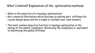
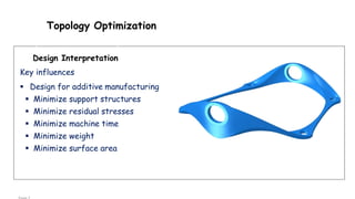
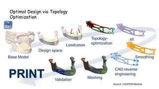
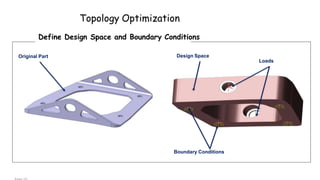
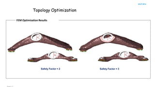
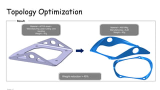
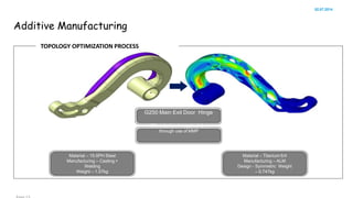
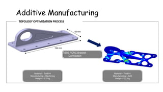
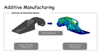
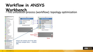
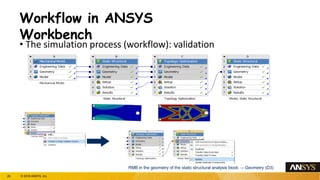
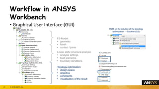
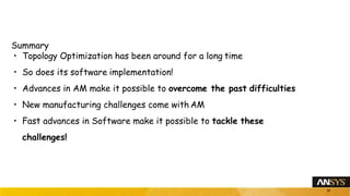
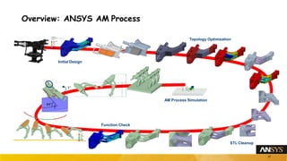
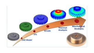
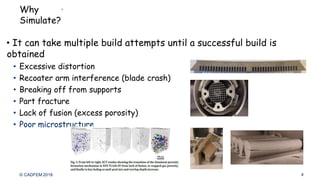
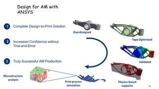
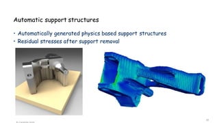
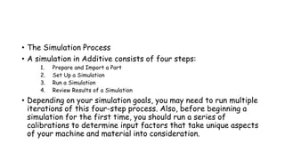
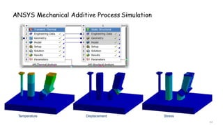
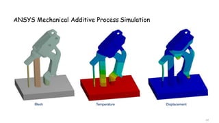
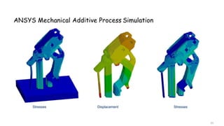
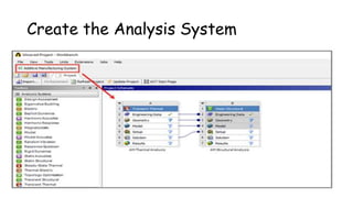
BAHIR DAR UNIVERSITY
BAHIR DAR INSTITUTE OF TECHNOLOGY (BiT)
FACULTY OF MECHANICAL AND INDUSTRIAL
ENGINEERING
Rapid Prototyping & Reverse Engineering
[MEng6123]
Tools for Additive Manufacturing
ANSYS
Topics
• Topology Optimization in ANSYS
• ANSYS Additive
• AM Process Simulation Workflow - With the Additive Wizard
The Additive Manufacturing Potential
1. Impossible to Manufacture
2. Lightweighting
3. Part Consolidation
4. Multifunctional Designs
5. Distributed Production
6. New Material Properties
7. Replacement Parts
8. Customization
9. …
Topology Optimization
SizeShape
Topology
What is Topology Optimization?
• A technique for optimum material
distribution in a given design domain.
• Why do topology optimization?
• Able to achieve the optimal design
without depending on designers’ a
priori knowledge.
• More powerful than shape and size
optimization.
~ 3 ~
Why Topology optimization?
• Extreme performance increase
• Lightweight parts
• Stronger parts
• Part cost reduction
What's behind? Explanation of the optimization methods
6
• What is the objective of a topology optimization?
• Get a material distribution which provides an optimal part stiffness for
a given design space and for a single or multiple load case scenario
• The most common objective function in topology optimization is the
energy of the elastic compliance. Minimizing the compliance is equivalent
to maximizing the global stiffness
Topology Optimization
Design Interpretation
Key influences
 Design for additive manufacturing
 Minimize support structures
 Minimize residual stresses
 Minimize machine time
 Minimize weight
 Minimize surface area
Software… soft procedure
• Modeling
• Analysis
• Optimizing
• Remodeling
• Producing manufacturable design
Optimal Design via Topology
Optimization
Base Model
Design space
Loadcases
Topology-
optimization
Smoothing
.stl
CAD reverse
engineering
Meshing
Validation
Source: CADFEM Medical
PRINT
Topology Optimization
Define Design Space and Boundary Conditions
Boundary Conditions
Loads
Design SpaceOriginal Part
Topology Optimization
02.07.2014
FEM Optimization Results
Safety Factor = 2 Safety Factor = 3
Topology Optimization
Result
Weight reduction > 45%
Material – Al7XX sheet –
Manufacturing Laser cutting and
bending
Weight – 81g
Material – AlSi10Mg
Manufacturing –ALM
Weight – 43g
Additive Manufacturing
02.07.2014
TOPOLOGY OPTIMIZATION PROCESS
Material – 15-5PH Steel
Manufacturing – Casting +
Welding
Weight – 1.57kg
Material – Titanium 6/4
Manufacturing – ALM
Design - Symmetric Weight
– 0.747kg
G250 Main Exit Door Hinge
45% reduction in required time
through use of MMP
Additive Manufacturing
TOPOLOGY OPTIMIZATION PROCESS
65 mm
164 mm
A350 FCRC Bracket
Connection
Material – TiAl6V4
Manufacturing – Machining
Weight – 0.37kg
Material – TiAl6V4
Manufacturing –ALM
Weight – 0.21kg
Additive Manufacturing
TOPOLOGY OPTIMIZATION PROCESS
Material – HC101 Steel
Manufacturing – Casting
Weight – 0.97kg
Material – Titanium 6/4
Manufacturing – ALM
Weight – 0.36kg
A320 Nacelle Hinge
Topology Optimization is not
enough
CNC
Machined
3D Printed
1
Workflow in ANSYS
Workbench
18 © 2018 ANSYS, Inc.
Workflow in ANSYS
Workbench• The simulation process (workflow): topology optimization
fixed support
force
Drag to the solution cell of the static
structural analysis block → Solution
(B6)
19 © 2018 ANSYS, Inc.
Workflow in ANSYS
Workbench
• The simulation process (workflow): validation
RMB in the geometry of the static structural analysis block → Geometry (D3)
20 © 2018 ANSYS, Inc.
Workflow in ANSYS
Workbench
• Graphical User Interface (GUI)
FE-Model:
 geometry
 Mesh
 contact / joints
Linear static structural analysis:
 analysis settings
 load scenarios
 boundary conditions
Topology optimization:
 design space
 objective
 constraints
 visualization of the result
RMB on the solution of the topology
optimization → Solution (C6)
21 © 2018 ANSYS, Inc.
Workflow in ANSYS
Workbench
• GUI
Statisch-Mechanisch
Modal
22 © 2018 ANSYS, Inc.
Workflow in ANSYS
Workbench
• GUI
23 © 2018 ANSYS, Inc.
Workflow in ANSYS
Workbench
• GUI
24 © 2018 ANSYS, Inc.
Workflow in ANSYS
Workbench
• GUI
25 © 2018 ANSYS, Inc.
Summary
• Topology Optimization has been around for a long time
• So does its software implementation!
• Advances in AM make it possible to overcome the past difficulties
• New manufacturing challenges come with AM
• Fast advances in Software make it possible to tackle these
challenges!
26
Overview: ANSYS AM Process
1°
44°
Initial Design
27
Topology Optimization
STL Cleanup
Function Check
AM Process Simulation
18
Example: GE Jet Engine Bracket
http://grabcad.com/challenges/ge-jet-engine-bracket-challenge
Validate
Design Space Create FE Model Topology Optimization
Print
Preparation Optimized Design
Geometry
Finalize Design
http://www.vttresearch.com/
Erin.Komi@vtt.fi
19
ANSYS Additive
© CADFEM 2018
Why
Simulate?
• It can take multiple build attempts until a successful build is
obtained
• Excessive distortion
• Recoater arm interference (blade crash)
• Breaking off from supports
• Part fracture
• Lack of fusion (excess porosity)
• Poor microstructure
4
ANSYS Additive
• Simulation software dedicated to the field of metal additive
manufacturing.
• Offerings include:
• Additive Print – a tool for quick simulations of parts to ensure they will
print successfully
• Additive Science – an exploratory environment to determine the optimum
process parameters for machines and materials
Design for AM with
ANSYS
Truly Successful AM Production
12. Increased Confidence without
Trial-and-Error
13.
11. Complete Design-to-Print Solution
Overdesigned
TopoOptimized
Validated
Print process
simulation
Physics-based
supports
Microstructure
analysis
10
Fast Process Simulation
• For the Process Engineer and Machine Operator:
ANSYS Additive Print
• Optimize Process:
• Find good print direction
• Find good support strategy
• Find good print parameters
• “Inherent Strain” approach
• Fast simulation fast decision making
• Goal: Avoid failed prints
35
ANSYS Additive
Print
Software GUI
36
Application example: Distortion compensation
Compensated GeometryOriginal Geometry
37
Blade Crash Prediction
• As the part is being build, the recoater blade may run into the part
• Damaging the part, and potentially the machine
38
Automatic support structures
• Automatically generated physics based support structures
• Residual stresses after support removal
39
• The Simulation Process
• A simulation in Additive consists of four steps:
1. Prepare and Import a Part
2. Set Up a Simulation
3. Run a Simulation
4. Review Results of a Simulation
• Depending on your simulation goals, you may need to run multiple
iterations of this four-step process. Also, before beginning a
simulation for the first time, you should run a series of
calibrations to determine input factors that take unique aspects
of your machine and material into consideration.
Understanding the Additive Interface
Understanding Machine Parameters
Guidelines for Part Orientation and Resolution
• Do not include supports in the part geometry file. Import supports
separately or have the Additive application create supports
automatically for the part.
• Do not include a baseplate (build plate) in the part geometry file.
• Dimensions of the part must be in units of millimeters (mm).While .stl
files are unitless, the Additive application does not provide the ability
to switch unit systems and Metric units of millimeters are assumed.
• Currently, part size is limited to 600 millimeters in all directions. (The
maximum part is 600 x 600 x 600 mm).
• The .stl file must have the part positioned in the orientation in which
it will be printed.
• A part with its longest dimension in the Z direction will require the
longest simulation time.
• The time required to slice and voxelize an .stl file exponentially
increases with the number of triangles.
Importing a Part
Importing a Part
Importing a Build File
Set Up a Simulation –
• Assumed Strain
Set Up a Simulation –
• Assumed Strain
Set Up a Simulation –
• Assumed Strain
Set Up a Simulation –
• Assumed Strain
Set Up a Simulation –
• Assumed Strain
AM Process Simulation Workflow - With the Additive
Wizard
• For the Development Engineer:
ANSYS Mechanical Additive Process Simulation
• Familiar Mechanical interface
• Take advantage of full parametrization
• Include postprocessing steps after process
simulation (heat treatment, HIP)
• Include simulation of part function
after process simulation
• Coupled transient thermal and static analysis
• Goal:
Optimize process AND part design
Detailed Process Simulation
60
ANSYS Mechanical Additive Process Simulation
Workbench/Mechanical integrated, Wizard based setup
61
ANSYS Mechanical Additive Process
Simulation
Individual support structures, print orientation, process parameters…
Printdirection
ANSYS Mechanical Additive Process Simulation
Temperature
63
Displacement Stress
ANSYS Mechanical Additive Process Simulation
Mesh
64
Temperature Displacement
ANSYS Mechanical Additive Process Simulation
Stresses
65
Displacement Stresses
Create the Analysis System
Define Engineering Data
Attach Geometry and Launch
Mechanical
Identify Geometry (First Page of
Additive Wizard)
Generate Mesh and Contact Connections
(Second Page of Additive
Wizard)
Generate Supports (Third Page of
Additive Wizard)
Assign Materials (Fourth Page of
Additive Wizard)
Define AM Process Settings and
Sequence Steps (Fifth Page of Additive
Wizard)
Apply Boundary Conditions (Sixth
Page of Additive Wizard)
Solve the Transient Thermal Analysis
• To set up a plot of overall temperature that will be updated
throughout the solution, under Transient
Thermal, Solution, Solution Information, select Insert >
Temperature Plot Tracker.
2. Right-click on the Temperature plot tracker object and select
Switch to Automatic Mode. This will show
a live display as the solution progresses. Note that the plot
tracker object needs to be selected in order to
see the live display.
3. To initiate the solution, under Transient Thermal, highlight the
Solution object, right-click and select Solve.
Solve the Static Structural Analysis
• To set up a plot of overall deformation that will be updated
throughout the solution, under the Static
Structural object, Solution Information, select Insert >
Deformation Plot Tracker.
2. To initiate the solution, under Static Structural, highlight
the Solution object, right-click and select Solve.
3. While the simulation is solving, right-click on the Total
Deformation plot tracker object and select Switch
to Automatic Mode. This will show a live display as the
solution progresses.
Review Results
• Animate Thermal Results
Review Results
• Animate Structural Results
Check for Blade Crash
• Note
At this release, a Blade Interference Tool is available as a
Beta feature. It will predict where
blade interference will occur during the build process. Use
the Blade Interference Tool in lieu
of the procedure described next.

Lecture # 06 Tools for Additive Manufacturing ANSYS

  • 1.
    BAHIR DAR UNIVERSITY BAHIRDAR INSTITUTE OF TECHNOLOGY (BiT) FACULTY OF MECHANICAL AND INDUSTRIAL ENGINEERING Rapid Prototyping & Reverse Engineering [MEng6123] Tools for Additive Manufacturing ANSYS
  • 2.
    Topics • Topology Optimizationin ANSYS • ANSYS Additive • AM Process Simulation Workflow - With the Additive Wizard
  • 3.
    The Additive ManufacturingPotential 1. Impossible to Manufacture 2. Lightweighting 3. Part Consolidation 4. Multifunctional Designs 5. Distributed Production 6. New Material Properties 7. Replacement Parts 8. Customization 9. … Topology Optimization
  • 4.
    Topology Optimization SizeShape Topology What isTopology Optimization? • A technique for optimum material distribution in a given design domain. • Why do topology optimization? • Able to achieve the optimal design without depending on designers’ a priori knowledge. • More powerful than shape and size optimization. ~ 3 ~
  • 5.
    Why Topology optimization? •Extreme performance increase • Lightweight parts • Stronger parts • Part cost reduction
  • 6.
    What's behind? Explanationof the optimization methods 6 • What is the objective of a topology optimization? • Get a material distribution which provides an optimal part stiffness for a given design space and for a single or multiple load case scenario • The most common objective function in topology optimization is the energy of the elastic compliance. Minimizing the compliance is equivalent to maximizing the global stiffness
  • 7.
    Topology Optimization Design Interpretation Keyinfluences  Design for additive manufacturing  Minimize support structures  Minimize residual stresses  Minimize machine time  Minimize weight  Minimize surface area
  • 8.
    Software… soft procedure •Modeling • Analysis • Optimizing • Remodeling • Producing manufacturable design
  • 9.
    Optimal Design viaTopology Optimization Base Model Design space Loadcases Topology- optimization Smoothing .stl CAD reverse engineering Meshing Validation Source: CADFEM Medical PRINT
  • 10.
    Topology Optimization Define DesignSpace and Boundary Conditions Boundary Conditions Loads Design SpaceOriginal Part
  • 11.
    Topology Optimization 02.07.2014 FEM OptimizationResults Safety Factor = 2 Safety Factor = 3
  • 12.
    Topology Optimization Result Weight reduction> 45% Material – Al7XX sheet – Manufacturing Laser cutting and bending Weight – 81g Material – AlSi10Mg Manufacturing –ALM Weight – 43g
  • 13.
    Additive Manufacturing 02.07.2014 TOPOLOGY OPTIMIZATIONPROCESS Material – 15-5PH Steel Manufacturing – Casting + Welding Weight – 1.57kg Material – Titanium 6/4 Manufacturing – ALM Design - Symmetric Weight – 0.747kg G250 Main Exit Door Hinge 45% reduction in required time through use of MMP
  • 14.
    Additive Manufacturing TOPOLOGY OPTIMIZATIONPROCESS 65 mm 164 mm A350 FCRC Bracket Connection Material – TiAl6V4 Manufacturing – Machining Weight – 0.37kg Material – TiAl6V4 Manufacturing –ALM Weight – 0.21kg
  • 15.
    Additive Manufacturing TOPOLOGY OPTIMIZATIONPROCESS Material – HC101 Steel Manufacturing – Casting Weight – 0.97kg Material – Titanium 6/4 Manufacturing – ALM Weight – 0.36kg A320 Nacelle Hinge
  • 17.
    Topology Optimization isnot enough CNC Machined 3D Printed 1
  • 18.
    Workflow in ANSYS Workbench 18© 2018 ANSYS, Inc.
  • 19.
    Workflow in ANSYS Workbench•The simulation process (workflow): topology optimization fixed support force Drag to the solution cell of the static structural analysis block → Solution (B6) 19 © 2018 ANSYS, Inc.
  • 20.
    Workflow in ANSYS Workbench •The simulation process (workflow): validation RMB in the geometry of the static structural analysis block → Geometry (D3) 20 © 2018 ANSYS, Inc.
  • 21.
    Workflow in ANSYS Workbench •Graphical User Interface (GUI) FE-Model:  geometry  Mesh  contact / joints Linear static structural analysis:  analysis settings  load scenarios  boundary conditions Topology optimization:  design space  objective  constraints  visualization of the result RMB on the solution of the topology optimization → Solution (C6) 21 © 2018 ANSYS, Inc.
  • 22.
    Workflow in ANSYS Workbench •GUI Statisch-Mechanisch Modal 22 © 2018 ANSYS, Inc.
  • 23.
    Workflow in ANSYS Workbench •GUI 23 © 2018 ANSYS, Inc.
  • 24.
    Workflow in ANSYS Workbench •GUI 24 © 2018 ANSYS, Inc.
  • 25.
    Workflow in ANSYS Workbench •GUI 25 © 2018 ANSYS, Inc.
  • 26.
    Summary • Topology Optimizationhas been around for a long time • So does its software implementation! • Advances in AM make it possible to overcome the past difficulties • New manufacturing challenges come with AM • Fast advances in Software make it possible to tackle these challenges! 26
  • 27.
    Overview: ANSYS AMProcess 1° 44° Initial Design 27 Topology Optimization STL Cleanup Function Check AM Process Simulation
  • 28.
    18 Example: GE JetEngine Bracket http://grabcad.com/challenges/ge-jet-engine-bracket-challenge
  • 29.
    Validate Design Space CreateFE Model Topology Optimization Print Preparation Optimized Design Geometry Finalize Design http://www.vttresearch.com/ Erin.Komi@vtt.fi 19
  • 30.
  • 32.
    © CADFEM 2018 Why Simulate? •It can take multiple build attempts until a successful build is obtained • Excessive distortion • Recoater arm interference (blade crash) • Breaking off from supports • Part fracture • Lack of fusion (excess porosity) • Poor microstructure 4
  • 33.
    ANSYS Additive • Simulationsoftware dedicated to the field of metal additive manufacturing. • Offerings include: • Additive Print – a tool for quick simulations of parts to ensure they will print successfully • Additive Science – an exploratory environment to determine the optimum process parameters for machines and materials
  • 34.
    Design for AMwith ANSYS Truly Successful AM Production 12. Increased Confidence without Trial-and-Error 13. 11. Complete Design-to-Print Solution Overdesigned TopoOptimized Validated Print process simulation Physics-based supports Microstructure analysis 10
  • 35.
    Fast Process Simulation •For the Process Engineer and Machine Operator: ANSYS Additive Print • Optimize Process: • Find good print direction • Find good support strategy • Find good print parameters • “Inherent Strain” approach • Fast simulation fast decision making • Goal: Avoid failed prints 35
  • 36.
  • 37.
    Application example: Distortioncompensation Compensated GeometryOriginal Geometry 37
  • 38.
    Blade Crash Prediction •As the part is being build, the recoater blade may run into the part • Damaging the part, and potentially the machine 38
  • 39.
    Automatic support structures •Automatically generated physics based support structures • Residual stresses after support removal 39
  • 40.
    • The SimulationProcess • A simulation in Additive consists of four steps: 1. Prepare and Import a Part 2. Set Up a Simulation 3. Run a Simulation 4. Review Results of a Simulation • Depending on your simulation goals, you may need to run multiple iterations of this four-step process. Also, before beginning a simulation for the first time, you should run a series of calibrations to determine input factors that take unique aspects of your machine and material into consideration.
  • 41.
  • 42.
  • 43.
  • 44.
  • 45.
  • 46.
  • 47.
  • 48.
  • 49.
    Guidelines for PartOrientation and Resolution • Do not include supports in the part geometry file. Import supports separately or have the Additive application create supports automatically for the part. • Do not include a baseplate (build plate) in the part geometry file. • Dimensions of the part must be in units of millimeters (mm).While .stl files are unitless, the Additive application does not provide the ability to switch unit systems and Metric units of millimeters are assumed. • Currently, part size is limited to 600 millimeters in all directions. (The maximum part is 600 x 600 x 600 mm). • The .stl file must have the part positioned in the orientation in which it will be printed. • A part with its longest dimension in the Z direction will require the longest simulation time. • The time required to slice and voxelize an .stl file exponentially increases with the number of triangles.
  • 50.
  • 51.
  • 52.
  • 53.
  • 54.
    Set Up aSimulation – • Assumed Strain
  • 55.
    Set Up aSimulation – • Assumed Strain
  • 56.
    Set Up aSimulation – • Assumed Strain
  • 57.
    Set Up aSimulation – • Assumed Strain
  • 58.
    Set Up aSimulation – • Assumed Strain
  • 59.
    AM Process SimulationWorkflow - With the Additive Wizard
  • 60.
    • For theDevelopment Engineer: ANSYS Mechanical Additive Process Simulation • Familiar Mechanical interface • Take advantage of full parametrization • Include postprocessing steps after process simulation (heat treatment, HIP) • Include simulation of part function after process simulation • Coupled transient thermal and static analysis • Goal: Optimize process AND part design Detailed Process Simulation 60
  • 61.
    ANSYS Mechanical AdditiveProcess Simulation Workbench/Mechanical integrated, Wizard based setup 61
  • 62.
    ANSYS Mechanical AdditiveProcess Simulation Individual support structures, print orientation, process parameters… Printdirection
  • 63.
    ANSYS Mechanical AdditiveProcess Simulation Temperature 63 Displacement Stress
  • 64.
    ANSYS Mechanical AdditiveProcess Simulation Mesh 64 Temperature Displacement
  • 65.
    ANSYS Mechanical AdditiveProcess Simulation Stresses 65 Displacement Stresses
  • 66.
  • 67.
  • 68.
    Attach Geometry andLaunch Mechanical
  • 69.
    Identify Geometry (FirstPage of Additive Wizard)
  • 70.
    Generate Mesh andContact Connections (Second Page of Additive Wizard)
  • 71.
    Generate Supports (ThirdPage of Additive Wizard)
  • 72.
    Assign Materials (FourthPage of Additive Wizard)
  • 73.
    Define AM ProcessSettings and Sequence Steps (Fifth Page of Additive Wizard)
  • 74.
    Apply Boundary Conditions(Sixth Page of Additive Wizard)
  • 75.
    Solve the TransientThermal Analysis • To set up a plot of overall temperature that will be updated throughout the solution, under Transient Thermal, Solution, Solution Information, select Insert > Temperature Plot Tracker. 2. Right-click on the Temperature plot tracker object and select Switch to Automatic Mode. This will show a live display as the solution progresses. Note that the plot tracker object needs to be selected in order to see the live display. 3. To initiate the solution, under Transient Thermal, highlight the Solution object, right-click and select Solve.
  • 76.
    Solve the StaticStructural Analysis • To set up a plot of overall deformation that will be updated throughout the solution, under the Static Structural object, Solution Information, select Insert > Deformation Plot Tracker. 2. To initiate the solution, under Static Structural, highlight the Solution object, right-click and select Solve. 3. While the simulation is solving, right-click on the Total Deformation plot tracker object and select Switch to Automatic Mode. This will show a live display as the solution progresses.
  • 77.
  • 78.
    Review Results • AnimateStructural Results
  • 79.
    Check for BladeCrash • Note At this release, a Blade Interference Tool is available as a Beta feature. It will predict where blade interference will occur during the build process. Use the Blade Interference Tool in lieu of the procedure described next.