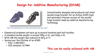
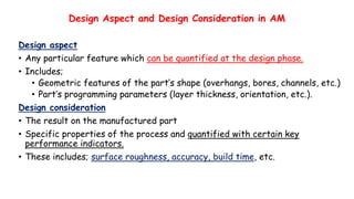
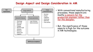
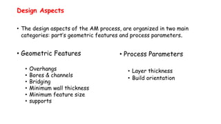
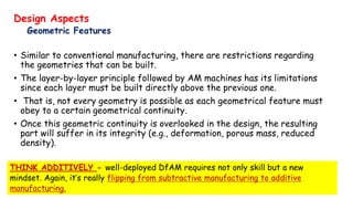
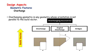
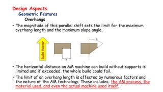
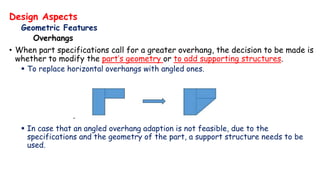
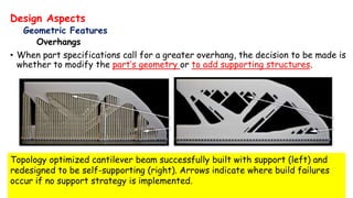
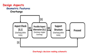
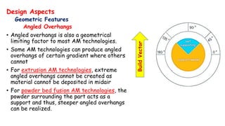
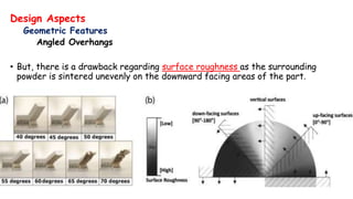
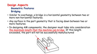
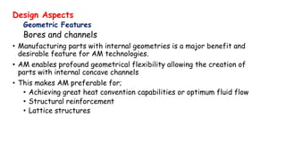
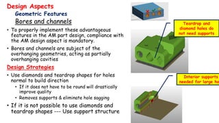
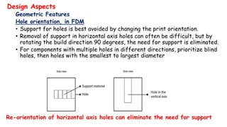
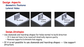
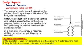
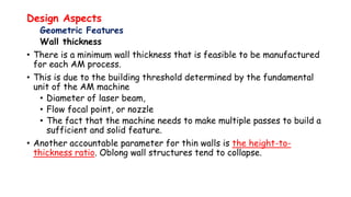
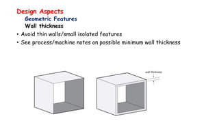
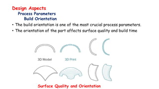
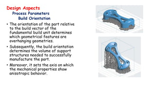
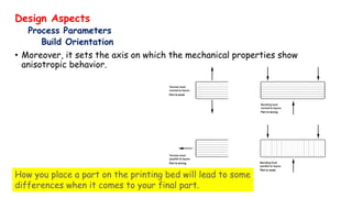
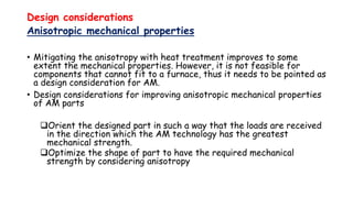
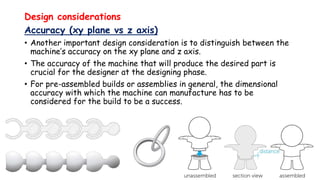
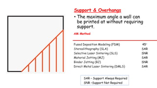
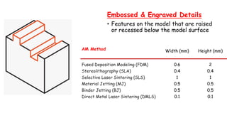
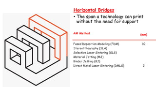
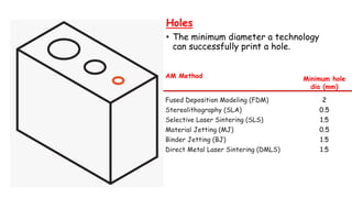
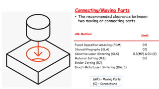
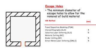
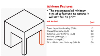
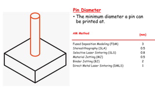
Design for Additive Manufacturing (DfAM)
DfAM - A generic term used to describe rules and parameters for a part design to be produced with an AM process
DfAM - is the practice of designing products to reduce or minimize manufacturing and assembly difficulties and costs,
DfAM aims
To take advantages of the unique AM technologies capabilities to design and optimize a product/component,
To utilize the characteristics of AM methods to improve the product/component functions according to the capability of the selected AM process.
In doing so, the designers should tailor their designs to maximize the advantages of AM methods, such as complex geometries and lightweight
Design Aspect and Design Consideration in AM
Design aspect
Any particular feature which can be quantified at the design phase.
Includes;
Geometric features of the part’s shape (overhangs, bores, channels, etc.)
Part’s programming parameters (layer thickness, orientation, etc.).
Design consideration
The result on the manufactured part
Specific properties of the process and quantified with certain key performance indicators.
These includes; surface roughness, accuracy, build time, etc.
Design Aspect and Design Consideration in AM
With conventional manufacturing processes, these aspects are mostly a concern for the production engineer rather than for the designer;
But, the significance of these aspects is high for the outcome in AM technologies.
Product Development & Design for Additive Manufacturing (DfAM)Katie Marzocchi
Product Development & DfAM in the Dawn of Digital Transformation
Empire Group provides a glimpse into the future of product development and how an understanding of DfAM is critical to the success of PD professionals and manufacturers alike. You’ll learn some of the basic fundamentals of DfAM and see real-world design examples and optimizations from Empire Group’s Design & Engineering team.
Website: www.empiregroupusa.com
Phone: 508-222-3003
email: info@empirepd.com
this short ppt gives you a rough idea about the additive manufacturing process of stereolithography. This process is apart of 3d printing technologies around us. Also included is link to a video that will help you further.
Purpose Statement:
To provide an overview of Design for Manufacturing and Assembly (DFMA) techniques, which are used to minimize product cost through design and process improvements.
Welding Fixture, some attention in welding fixture design,Application of modular fixture and dedicated fixture,Fixture design verification
Ref. - elsevier journals
BAHIR DAR UNIVERSITYBAHIR DAR INSTITUTE OF TECHNOLOGY (BiT)FACULTY OF MECHANICAL AND INDUSTRIAL ENGINEERING Rapid Prototyping & Reverse Engineering [MEng6123]
Post processing of AM parts
Post processing of AM parts Preparation for use as a Pattern Often
Guidelines for process selection
Guidelines for process selection Approaches to Selection
Guidelines for process selection Selection Example
Guidelines for process selection - Selection Example
In this example, it is decided to allow customization of certain features.
Only standard 12 mm diameter x 100 mm length bolts will be used for the inner bore, therefore, these dimensions will be constrained.
Customers will be allowed to customize all other features of the caster wheel
within allowable ranges for this model wheel, as displayed in the table below.
Guidelines for process selection - Selection Example
Guidelines for process selection Selection Example
In this example, we examine two weighting scenarios (relative importance ratings).
Scenario 2
All selection attributes were equally weighted.
Guidelines for process selection Selection Example
Design for Manufacturability power point presentation,
This PPT improve the study of design for manufacturability.
DFM is utilized in many industries ranging from industrial products, microelectronics, scientific instruments, and the aerospace industry
To design a product that can be easily, efficiently, and cost effectively be manufactured
To reduce overall cost of a product – warranty, engineering changes, factory floor space, unnecessary parts, and service
Using modules simplifies the manufacturing process
Allows for the use of standard components
Allows for tests to be conducted prior to the product being assembled
Using parts for the same or different operations multiple times in a product
Reduces the number of parts that need to be developed
Less machines - Less usage of factory floor space
Optimal assembly of a product occurs in one direction
Preferred direction is from above using gravity to assist in the manufacturing process
Errors in insertion due to positioning and dimensional variability cause damage to parts and to machinery
Use tapers, chamfers and moderate radii to ease insertion
Example – utilization of a rigid base and tactile and visual sensors in assembly
Positioning, orienting, and fixing a part are time consuming and costly
Use external guiding features to orient the part
Ideally the part should be placed one time
The process of designing the product and the manufacturing process simultaneously to increase the efficiency and reduce the time to launch a product
This presentation is intended to enable the sales team about the capabilities of NX CAM.
It covers fundamentals of machining, types of CNC Machining and Advanced capabilities of NX CAM
Design for Manufacturability Guidelines Every Designer should FollowDFMPro
Learn some important design for manufacturing guidelines for designing sheet metal parts and see how you can easily automate and configure the DFM review process in your organization so that you don’t a miss a single design guideline while designing your product. To know more visit http://dfmpro.geometricglobal.com/
3D Printing to CNC Machining Making the transition Fictiv
Moving your hardware project from 3D printing and other early stage prototyping to CNC machining can be a difficult decision.
Machining is often a costly process and there are many materials available, so it’s best to get things right the first time.
In this presentation we look at tips, trick and things to look out for when getting parts ready for the transition.
Some of the specific issues addressed are:
- Common pitfalls
- Communicating design intent
- Transitioning to CNC, CNC in the product development cycle
- Machine planning / programming
These slides are taken from a Fictiv webinar on June 30. You can watch the webinar at https://www.youtube.com/watch?v=O-7kkmJ_fkQ&feature=youtu.be
Reverse Engineering
Definition
It is described in Wikipedia as:
… the process of extracting knowledge or design information from anything man-made. The process often involves disassembling something (a mechanical device, electronic component, computer program, or biological, chemical, or organic matter) and analyzing its components and workings in detail.
Reverse Engineering
Definition
A process of discovering the technological principles of a human made device, object or system through analysis of its structure, function and operation
Systematic evaluation of a product with the purpose of replication.
Design of a new part
Copy of an existing part
Recovery of a damaged or broken part
An important step in the product development cycle.
Lecture # 06 Tools for Additive Manufacturing ANSYSSolomon Tekeste
The Additive Manufacturing Potential
Topology Optimization
A technique for optimum material distribution in a given design domain.
Why do topology optimization?
Able to achieve the optimal design without depending on designers’ a priori knowledge.
More powerful than shape and size optimization.
Why Topology optimization?
What's behind? Explanation of the optimization methods
Topology Optimization
Software… soft procedure
Optimal Design via Topology Optimization
Topology Optimization
Materials for AM Processes
Numerous laboratories around the world have researched and developed materials for various AM processes.
Below is a list of commercially available materials systems from a selected list of current manufacturers. Together they include;
Photo-curing resins,
Viscous-binder polymers,
Infiltrated metal,
Direct metal and
Infiltrated non-metallics.
Materials for AM Processes
Stereolithography.
All commercial photopolymers for SLA are proprietary epoxies and acrylate–epoxy hybrids. 3D Systems markets the following photopolymers currently.
BAHIR DAR UNIVERSITYBAHIR DAR INSTITUTE OF TECHNOLOGY (BiT)FACULTY OF MECHANICAL AND INDUSTRIAL ENGINEERING Rapid Prototyping & Reverse Engineering [MEng6123]
Rapid Prototyping Techniques
They can be categorized by material: photopolymer, thermoplastic, and adhesives.
Photopolymer systems start with a liquid resin, which is then solidified by exposure to a specific wavelength of light.
Thermoplastic systems begin with a solid material, which is then melted and fuses upon cooling.
The adhesive systems use a binder to connect the primary construction material
Rapid Prototyping Techniques
The initial state of material can come in either
solid, liquid or powder state
The current range materials include
paper, polymer, nylon, wax, resins, metals and ceramics.
Liquid Based RP Systems
Solidification of a Liquid Polymer
These process involve the solidification of a resin via electromagnetic radiation
There are different processes in this category
Stereolithography (SL)
Liquid Thermal Polymerization (LTP)
Beam Interference Solidification (BIS)
Solid Ground Curing (SGC)
Objet Quadra Process (Objet)
Holographic Interference Solidification
Liquid Based RP Systems
Stereolithography (SL)
Principle of Operation
Patented in 1986,
Started the RP revolution
Developed by 3D Systems, Inc.
Most popular RP methods.
The technique builds 3D models from liquid photosensitive polymers that solidify when exposed to ultraviolet light.
Builds plastic parts a layer at a time by tracing a laser beam on the surface of a vat of liquid photopolymer.
The liquid photopolymer, quickly solidifies wherever the laser beam strikes the surface of the liquid
Rapid prototyping (RP)
Definition
Rapid prototyping is a layer based automated fabrication process for making scaled 3-dimentional (3D) physical objects directly from 3D computer-aided design (CAD) data without using part depending tools.
More concisely, it is a process of building a prototype in one step.
Construction of the part or assembly is usually done using 3D printing or “additive layer manufacturing” technology.
Historical development
The first method for rapid prototyping became available in the late 1980s and was used to produce models and prototype parts.
Historical development
In today’s industry, RP exceeding the scope of prototype model creation, expands the possibility of the layered manufacturing, into the next level, where parts for real-world engineering applications are fabricated.
Historical development
Titanium powder-based 3D printing technology is reported recently with many successful stories.
For example, a 3D-printed bike has been fabricated with the Titanium powder.
BAHIR DAR UNIVERSITYBAHIR DAR INSTITUTE OF TECHNOLOGY (BiT)FACULTY OF MECHANICAL AND INDUSTRIAL ENGINEERING Rapid Prototyping & Reverse Engineering [MEng6123]
Tools for Reverse Engineering (Hardware & Software)
Reverse Engineering hardware used for data accusation.
The output of RE data accusation are 2-D cross-sectional image & point clouds that define the geometry of an object.
RE Software transforms RE data produced by RE hardware into a 3D geometric models.
The RE data processing chain can be one of two types
Polygon
Curves
Polygon models are commonly used rapid prototyping, laser milling, 3D Graphics, Simulation and animations.
Tools for Reverse Engineering (Hardware & Software)
Reverse Engineering Software
ANSYS SpaceClaim
SolidWorks
Catia
Geomagic Design X,…
Reverse Engineering Software
Geomagic Design X Introductory Tutorial
Interface
File Import
Live Scan
Point Processing
Regions
Reference Geometry
Align
Repair Mesh
CAD Modeling
Auto surface
Export
Reverse Engineering Software
Geomagic Design X Introductory Tutorial
Point Processing
Edit Mesh
Optimize mesh data to improve its quality. The following tools will be used to edit a mesh:
Heal mesh
Global remesh
Decimate
Fill holes
Enhance shape
Edit boundaries
Optimize mesh
BAHIR DAR UNIVERSITYBAHIR DAR INSTITUTE OF TECHNOLOGY (BiT)FACULTY OF MECHANICAL AND INDUSTRIAL ENGINEERING Rapid Prototyping & Reverse Engineering [MEng6123]
Reverse Engineering
Coordinate Measuring Machine (CMM)
Coordinate Measuring Machines (CMM)
A Coordinate Measuring Machine (CMM) is an electromechanical system designed to perform coordinate metrology.
CMM is a device for measuring the physical geometrical characteristics of an object.
CMM Applications
Types of CMM
Cantilever Type
Moving bridge type
Fixed bridge type
Column type
Gantry type
Horizontal arm type
Portable type
1. Cantilever Type of CMM
2. Moving Bridge type
3.Fixed bridge type
4. Column type CMM
5. Horizontal arm type CMM
6. Gantry type CMM
Types of Probe
Contact probe
Hard probe
Switching probes
Measuring probes
Non-contact probes
Laser probe
Vision probe
Hard Probe
It has a variety of probe tip shape and size based on the application.
Ball/Spherical shape probe used for establishing surface locations.
Tapered or conical probe used for locating holes.
Cylindrical probe used for checking slots and holes in sheet metal.
Switching Probes
3. Measuring Probes
2. Vision Probe
CAUSES OF ERRORS IN CMM
Threshing—It is the process of detaching the kernels from the ears/pods/ or panicles by a combination of impact and rubbing action.
It is accomplished either by treading the harvested crop under the feet of man or hooves of animals, and/or beating the harvested crop with stick or striking the harvested crop on hard and rough surface or using mechanical thresher.
Harvesting operations are one of the farm field operation in which seeds are separated from the stalk on which they grow. This is done when crops are ripened and reached maturity.
In order to achieve increased yield, the crops that are cultivated should be harvested at appropriate harvest time and moisture content. Both delayed and early harvesting results in decreased yield.
Definition
The operation of cutting, picking, digging or any combination of these for removing the whole crop or edible part of the crop from either under the ground or above the ground is called harvesting.
Introduction
Crop planting operation is the art of placing seed in the soil to obtain good germination and crop stands.
A perfect sowing gives
Correct amount of seed per unit area.
Correct depth of sowing
Correct spacing between row-to-row and plant to plant.
Correct seed rate
A farm machinery and/or implement can be defined as any type of machinery or implement that can be used in the process of agricultural production; it can be for crop production or animal production.
INTRODUCTION
Tillage may be defined as the mechanical manipulation of soil for nurturing crops.
The objectives of soil tillage are:
To develop a desirable soil structure for a seedbed
To control weeds or remove unwanted crop plants.
To manage plant residues.
To minimize soil erosion by following such practices as contour tillage
To establish specific surface configurations for planting, irrigating, drainage, or harvesting operations.
To incorporate and mix fertilizers, manure, pesticides
TECHNICAL TRAINING MANUAL GENERAL FAMILIARIZATION COURSEDuvanRamosGarzon1
AIRCRAFT GENERAL
The Single Aisle is the most advanced family aircraft in service today, with fly-by-wire flight controls.
The A318, A319, A320 and A321 are twin-engine subsonic medium range aircraft.
The family offers a choice of engines
Event Management System Vb Net Project Report.pdfKamal Acharya
In present era, the scopes of information technology growing with a very fast .We do not see any are untouched from this industry. The scope of information technology has become wider includes: Business and industry. Household Business, Communication, Education, Entertainment, Science, Medicine, Engineering, Distance Learning, Weather Forecasting. Carrier Searching and so on.
My project named “Event Management System” is software that store and maintained all events coordinated in college. It also helpful to print related reports. My project will help to record the events coordinated by faculties with their Name, Event subject, date & details in an efficient & effective ways.
In my system we have to make a system by which a user can record all events coordinated by a particular faculty. In our proposed system some more featured are added which differs it from the existing system such as security.
COLLEGE BUS MANAGEMENT SYSTEM PROJECT REPORT.pdfKamal Acharya
The College Bus Management system is completely developed by Visual Basic .NET Version. The application is connect with most secured database language MS SQL Server. The application is develop by using best combination of front-end and back-end languages. The application is totally design like flat user interface. This flat user interface is more attractive user interface in 2017. The application is gives more important to the system functionality. The application is to manage the student’s details, driver’s details, bus details, bus route details, bus fees details and more. The application has only one unit for admin. The admin can manage the entire application. The admin can login into the application by using username and password of the admin. The application is develop for big and small colleges. It is more user friendly for non-computer person. Even they can easily learn how to manage the application within hours. The application is more secure by the admin. The system will give an effective output for the VB.Net and SQL Server given as input to the system. The compiled java program given as input to the system, after scanning the program will generate different reports. The application generates the report for users. The admin can view and download the report of the data. The application deliver the excel format reports. Because, excel formatted reports is very easy to understand the income and expense of the college bus. This application is mainly develop for windows operating system users. In 2017, 73% of people enterprises are using windows operating system. So the application will easily install for all the windows operating system users. The application-developed size is very low. The application consumes very low space in disk. Therefore, the user can allocate very minimum local disk space for this application.
Vaccine management system project report documentation..pdfKamal Acharya
The Division of Vaccine and Immunization is facing increasing difficulty monitoring vaccines and other commodities distribution once they have been distributed from the national stores. With the introduction of new vaccines, more challenges have been anticipated with this additions posing serious threat to the already over strained vaccine supply chain system in Kenya.
Forklift Classes Overview by Intella PartsIntella Parts
Discover the different forklift classes and their specific applications. Learn how to choose the right forklift for your needs to ensure safety, efficiency, and compliance in your operations.
For more technical information, visit our website https://intellaparts.com
Industrial Training at Shahjalal Fertilizer Company Limited (SFCL)MdTanvirMahtab2
This presentation is about the working procedure of Shahjalal Fertilizer Company Limited (SFCL). A Govt. owned Company of Bangladesh Chemical Industries Corporation under Ministry of Industries.
Overview of the fundamental roles in Hydropower generation and the components involved in wider Electrical Engineering.
This paper presents the design and construction of hydroelectric dams from the hydrologist’s survey of the valley before construction, all aspects and involved disciplines, fluid dynamics, structural engineering, generation and mains frequency regulation to the very transmission of power through the network in the United Kingdom.
Author: Robbie Edward Sayers
Collaborators and co editors: Charlie Sims and Connor Healey.
(C) 2024 Robbie E. Sayers
Immunizing Image Classifiers Against Localized Adversary Attacksgerogepatton
This paper addresses the vulnerability of deep learning models, particularly convolutional neural networks
(CNN)s, to adversarial attacks and presents a proactive training technique designed to counter them. We
introduce a novel volumization algorithm, which transforms 2D images into 3D volumetric representations.
When combined with 3D convolution and deep curriculum learning optimization (CLO), itsignificantly improves
the immunity of models against localized universal attacks by up to 40%. We evaluate our proposed approach
using contemporary CNN architectures and the modified Canadian Institute for Advanced Research (CIFAR-10
and CIFAR-100) and ImageNet Large Scale Visual Recognition Challenge (ILSVRC12) datasets, showcasing
accuracy improvements over previous techniques. The results indicate that the combination of the volumetric
input and curriculum learning holds significant promise for mitigating adversarial attacks without necessitating
adversary training.
Design and Analysis of Algorithms-DP,Backtracking,Graphs,B&B
Lecture # 03 Design for Additive Manufacturing
1. BAHIR DAR UNIVERSITY
BAHIR DAR INSTITUTE OF TECHNOLOGY (BiT)
FACULTY OF MECHANICAL AND INDUSTRIAL
ENGINEERING
Rapid Prototyping & Reverse Engineering
[MEng6123]
Design for Additive Manufacturing (DfAM)
2. Design for Additive Manufacturing (DfAM)
• DfAM - A generic term used to describe rules and parameters for a part design to
be produced with an AM process
• DfAM - is the practice of designing products to reduce or minimize manufacturing
and assembly difficulties and costs,
• DfAM aims
• To take advantages of the unique AM technologies capabilities to design and
optimize a product/component,
• To utilize the characteristics of AM methods to improve the product/component
functions according to the capability of the selected AM process.
• In doing so, the designers should tailor their designs to maximize the advantages of
AM methods, such as complex geometries and lightweight
3. EN-MME/ Th. Sahner 3
Additive Manufacturing
Short introduction to the technology
“SEE THE DIFFERENCE IN THE CONCEPTION OF THE PART”
Conventionally designed and produced cast steel
nacelle hinge bracket for an Airbus A320 (top)
and optimised titanium version of the nacelle
hinge bracket made by additive manufacturing
technology.
• Commercial airplanes can have up to several hundred seat belt buckles.
• A standard buckle weight is around 155g in St. and 120g in Al.
• With AM the weight was reduced to 68 g in Ti.
• Saving over the lifetime of an A380:
• Fuel: 3.300.000 l
• CO2 emission: 0,74Mt
Design for Additive Manufacturing (DfAM)
This can be easily achieved with AM
4. Design Aspect and Design Consideration in AM
Design aspect
• Any particular feature which can be quantified at the design phase.
• Includes;
• Geometric features of the part’s shape (overhangs, bores, channels, etc.)
• Part’s programming parameters (layer thickness, orientation, etc.).
Design consideration
• The result on the manufactured part
• Specific properties of the process and quantified with certain key
performance indicators.
• These includes; surface roughness, accuracy, build time, etc.
5. Design Aspect and Design Consideration in AM
• With conventional manufacturing
processes, these aspects are
mostly a concern for the
production engineer rather than
for the designer;
• But, the significance of these
aspects is high for the outcome
in AM technologies.
6. Design Aspects
• The design aspects of the AM process, are organized in two main
categories: part’s geometric features and process parameters.
• Geometric Features
• Overhangs
• Bores & channels
• Bridging
• Minimum wall thickness
• Minimum feature size
• supports
• Process Parameters
• Layer thickness
• Build orientation
7. Design Aspects
Geometric Features
• Similar to conventional manufacturing, there are restrictions regarding
the geometries that can be built.
• The layer-by-layer principle followed by AM machines has its limitations
since each layer must be built directly above the previous one.
• That is, not every geometry is possible as each geometrical feature must
obey to a certain geometrical continuity.
• Once this geometric continuity is overlooked in the design, the resulting
part will suffer in its integrity (e.g., deformation, porous mass, reduced
density).
THINK ADDITIVELY - well-deployed DfAM requires not only skill but a new
mindset. Again, it’s really flipping from subtractive manufacturing to additive
manufacturing.
9. Design Aspects
Geometric Features
Overhangs
• The magnitude of this parallel shift sets the limit for the maximum
overhang length and the maximum slope angle.
• The horizontal distance an AM machine can build without supports is
limited and if exceeded, the whole build could fail.
• The limit of an overhang length is affected by numerous factors and
the nature of the AM technology. These includes; the AM process, the
material used, and even the actual machine used itself.
BuildVector
10. Design Aspects
Geometric Features
Overhangs
• When part specifications call for a greater overhang, the decision to be made is
whether to modify the part’s geometry or to add supporting structures.
To replace horizontal overhangs with angled ones.
In case that an angled overhang adaption is not feasible, due to the
specifications and the geometry of the part, a support structure needs to be
used.
11. Design Aspects
Geometric Features
Overhangs
• When part specifications call for a greater overhang, the decision to be made is
whether to modify the part’s geometry or to add supporting structures.
Topology optimized cantilever beam successfully built with support (left) and
redesigned to be self-supporting (right). Arrows indicate where build failures
occur if no support strategy is implemented.
13. Design Aspects
Geometric Features
Angled Overhangs
• Angled overhangs is also a geometrical
limiting factor to most AM technologies.
• Some AM technologies can produce angled
overhangs of certain gradient where others
cannot
• For extrusion AM technologies, extreme
angled overhangs cannot be created as
material cannot be deposited in midair
• For powder bed fusion AM technologies, the
powder surrounding the part acts as a
support and thus, steeper angled overhangs
can be realized.
BuildVector
14. Design Aspects
Geometric Features
Angled Overhangs
• But, there is a drawback regarding surface roughness as the surrounding
powder is sintered unevenly on the downward facing areas of the part.
15. Design Aspects
Geometric Features
Bridging
• Similar to overhangs, a bridge is a horizontal geometry between two or
more non-horizontal features.
• Any surface in the part geometry that is facing down between two or
more features.
• In designing AM components, the designer must take into consideration
the maximum length that the machine can bridge. If this length
exceeded, the part will not be successfully manufactured
16. Design Aspects
Geometric Features
Bores and channels
• Manufacturing parts with internal geometries is a major benefit and
desirable feature for AM technologies.
• AM enables profound geometrical flexibility allowing the creation of
parts with internal concave channels
• This makes AM preferable for;
• Achieving great heat convention capabilities or optimum fluid flow
• Structural reinforcement
• Lattice structures
17. Design Aspects
Geometric Features
Bores and channels
• To properly implement these advantageous
features in the AM part design, compliance with
the AM design aspect is mandatory.
• Bores and channels are subject of the
overhanging geometries, acting as partially
overhanging cavities
Design Strategies
• Use diamonds and teardrop shapes for holes
normal to build direction
• If it does not have to be round will drastically
improve quality
• Removes supports & eliminate hole sagging
• If it is not possible to use diamonds and
teardrop shapes --- Use support structure
Teardrop and
diamond holes do
not need supports
Interior supports
needed for large ho
18. Design Aspects
Geometric Features
Hole orientation, in FDM
• Support for holes is best avoided by changing the print orientation.
• Removal of support in horizontal axis holes can often be difficult, but by
rotating the build direction 90 degrees, the need for support is eliminated.
• For components with multiple holes in different directions, prioritize blind
holes, then holes with the smallest to largest diameter
Re-orientation of horizontal axis holes can eliminate the need for support
19. Design Aspects
Geometric Features
Lateral Holes
Design Strategies
• Use diamonds and teardrop shapes for holes normal to build direction
• If it does not have to be round will drastically improve quality
• Removes supports & eliminate hole sagging
• If it is not possible to use diamonds and teardrop shapes --- Use support
structure
20. Design Aspects
Geometric Features
Vertical axis holes, in FDM
• The amount of undersize will depend on the
printer, the slicing software, the size of the
hole, and the material.
• Often, the reduction in diameter of vertical
axis holes is accounted for in the slicing
program, but accuracy can vary and several
test prints may be needed to achieve the
desired accuracy.
• If a high level of accuracy is required,
drilling the hole after printing may be
required.
Key design consideration:
If the diameter of your vertical axis hole is critical, printing it undersized and then
drilling the hole to the correct diameter is recommended.
21. Design Aspects
Geometric Features
Wall thickness
• There is a minimum wall thickness that is feasible to be manufactured
for each AM process.
• This is due to the building threshold determined by the fundamental
unit of the AM machine
• Diameter of laser beam,
• Flow focal point, or nozzle
• The fact that the machine needs to make multiple passes to build a
sufficient and solid feature.
• Another accountable parameter for thin walls is the height-to-
thickness ratio. Oblong wall structures tend to collapse.
22. Design Aspects
Geometric Features
Wall thickness
• Avoid thin walls/small isolated features
• See process/machine notes on possible minimum wall thickness
23. Design Aspects
Geometric Features
Splitting up your model
• What if you have a part that is too big to print?
• Simply just segment the parts by cutting the part into whatever
sections will fit in the printer and then bond them together.
• Dovetail joints can be used to have strongest cut and joint.
• There are benefits of segmenting parts that do fit entirely in the
printer.
• If a couple of portions of the part were segmented away and printed
separately significant time and material savings can be had
24. Design Aspects
Geometric Features
Splitting up your model
• Reduce its complexity, saving on cost and time.
• Overhangs that require a large amount of support may be removed
• The sections can be glued together once the print has been completed.
25. Design Aspects
Geometric Features
Add hardware/Inserts
• There are many different types of hardware that can be added.
• For example, if you have hot or abrasive issues with parts you can add
bushings to those particular areas that are having contact issues.
Example
Conformal cooling channels in an injection molding die. The cooling tubes were inserted
into the substrate mold (left), the tubes were ‘buried’ and the die was completed using a
laser-aided metal-based AM process (center), and the final tool was post-machined
(right). Adapted from
26. Design Aspects
Geometric Features
Add hardware/Inserts
Threads
• Better ways of thread manufacturing is to go with
• heated inserts
• Mid-print insert
• In this way we can have metal threads in our 3D printed part and it
will be great for long-term use.
• Only print large threads
28. Design Aspects
Process Parameters
• Process parameters are selected at the slicing phase of the AM
process.
• They are highly interconnected with the AM technology and the
individual machine.
• The proper AM design considers the build orientation and the layer
thickness.
29. Design Aspects
Process Parameters
Layer Thickness
• Layer thickness is a factor that affects both the quality of the print
and the build time needed to complete the part.
• With smaller layer thickness,
• a more detailed part is produced,
• the staircase effect is minimized.
• potential voids and gaps are eliminated,
• the CAD file is being sliced with more precision and the geometry accuracy
is maintained.
• On the counterpart, with thicker layers, the printing time is reduced
• Regarding the staircase effect, another factor that is causing it is the
slope angle. As the angle increases, the stair size is proportionally
increasing
• A proposed solution to this matter is adaptive slicing.
30. Design Aspects
Process Parameters: Layer Thickness
Adaptive Slicing
• A proposed solution to this matter is adaptive slicing.
• The areas where detail is needed are sliced with thin layer height, whereas
areas that their quality is not affected are sliced with thicker layer height
to contribute to an effective build regarding time and energy consumption
31. Design Aspects
Process Parameters
Build Orientation
• The build orientation is one of the most crucial process parameters.
• The orientation of the part affects surface quality and build time
Surface Quality and Orientation
32. Design Aspects
Process Parameters
Build Orientation
• The orientation of the part relative
to the build vector of the
fundamental build unit determines
which geometrical features are
overhanging geometries.
• Subsequently, the build orientation
determines the volume of support
structures needed to successfully
manufacture the part.
• Moreover, it sets the axis on which
the mechanical properties show
anisotropic behavior.
33. Design Aspects
Process Parameters
Build Orientation
• Moreover, it sets the axis on which the mechanical properties show
anisotropic behavior.
How you place a part on the printing bed will lead to some
differences when it comes to your final part.
34. Design considerations
• Any resulted affection on the finished product. That includes mechanical
properties of the part, key performance indicators of the AM process or
even more abstract goals like first time right design and manufacture.
• Presented below are the most important design considerations.
• Anisotropic mechanical properties
• Accuracy
• Surface roughness
• Build time
• Part’s cross-section area
35. Design considerations
Anisotropic mechanical properties
• Anisotropic - (of an object or substance) having a physical property
which has a different value when measured in different directions.
• AM technologies produce parts with anisotropic mechanical properties.
• The causes of anisotropic behavior in AM includes
• Lamellar nature,
• Cylindrical extrusion shape (FFF technologies),
• Short fibers within the raw material, and
• Scaffold and lattice structures within the volume of the part
36. Design considerations
Anisotropic mechanical properties
Causes of anisotropic behavior in AM
Lamellar nature Cylindrical extrusion
shape FDM Process
Short fiber alignment
during the extrusion
process of a composite
Lattice Structure
39. Design considerations
Anisotropic mechanical properties
• Mitigating the anisotropy with heat treatment improves to some
extent the mechanical properties. However, it is not feasible for
components that cannot fit to a furnace, thus it needs to be pointed as
a design consideration for AM.
• Design considerations for improving anisotropic mechanical properties
of AM parts
Orient the designed part in such a way that the loads are received
in the direction which the AM technology has the greatest
mechanical strength.
Optimize the shape of part to have the required mechanical
strength by considering anisotropy
40. Design considerations
Accuracy (xy plane vs z axis)
• Another important design consideration is to distinguish between the
machine’s accuracy on the xy plane and z axis.
• The accuracy of the machine that will produce the desired part is
crucial for the designer at the designing phase.
• For pre-assembled builds or assemblies in general, the dimensional
accuracy with which the machine can manufacture has to be
considered for the build to be a success.
41. Design considerations
Surface roughness
• The roughness of the completed part is important, as it determines
the post-processing steps in order to achieve the desired surface
quality.
• The resulted surface roughness is not uniform throughout the entire
surface of the printed part.
• This is caused by the geometry’s slope angle and the unintentional
sintering under angled overhangs
• Another reason for surface non-uniformity is the gaps resulted from
insufficient filling of the path planning
42. Design considerations
Build time
• Refers to the total time required for an AM machine to manufacture
the part.
• The build time and build orientation of the part are highly related that
is due to the fact that material deposition speeds on xy plane and z
axis are not the same.
• The build unit (e.g., nozzle, laser) moves, thus builds the part, with
greater speed on the xy axis, then the speed that the layers are
adding up.
• Changing the build orientation will affect the time needed for the AM
machine to complete the part.
• Horizontally orientated parts will in general be printed faster than
vertically orientated ones.
43. Design considerations
Part’s cross-section area
• The part’s cross-section area (normal to build vector) is an important
design consideration.
• The cross-section area affects the manufacturing process in two ways
depending on the AM technology.
1. Machine’s build plate and part’s base consideration
• The first layers of the build are crucial for its completion.
• The part must be restrained at the build plate; thus, the adhesion
between the part’s base surface and the machine’s plate is to be
considered, apart from securing the part, through that common
surface heat dissipation is achieved.
• A thermal simulation for the heat concentration provides a picture for
the design engineer, regarding residual stresses
44. Design considerations
Part’s cross-section area
2. Part’s cross-section and developed stresses consideration
• For the AM technologies that develop residual stresses (e.g., FDM,
SLM), it is desirable to maintain a small cross-section area to minimize
residual stresses and thus deformation.
45. Supported Walls
• Walls that are connected to the
rest of the print on at least two
sides.
AM Method Minimum Wall
Thickness (mm)
Fused Deposition Modeling (FDM) 0.8
Stereolithography (SLA) 0.5
Selective Laser Sintering (SLS) 0.7
Material Jetting (MJ) 1
Binder Jetting (BJ) 2
Direct Metal Laser Sintering (DMLS) 0.4
46. Unsupported Walls
• Unsupported walls are
connected to the rest of the
print on less than two sides
AM Method Minimum Wall
Thickness (mm)
Fused Deposition Modeling (FDM) 0.8
Stereolithography (SLA) 1
Selective Laser Sintering (SLS) /
Material Jetting (MJ) 1
Binder Jetting (BJ) 3
Direct Metal Laser Sintering (DMLS) 0.5
47. Support & Overhangs
• The maximum angle a wall can
be printed at without requiring
support.
AM Method
Fused Deposition Modeling (FDM) 45°
Stereolithography (SLA) SAR
Selective Laser Sintering (SLS) SNR
Material Jetting (MJ) SAR
Binder Jetting (BJ) SNR
Direct Metal Laser Sintering (DMLS) SAR
SAR – Support Always Required
SNR –Support Not Required
48. Embossed & Engraved Details
• Features on the model that are raised
or recessed below the model surface
AM Method Width (mm) Height (mm)
Fused Deposition Modeling (FDM) 0.6 2
Stereolithography (SLA) 0.4 0.4
Selective Laser Sintering (SLS) 1 1
Material Jetting (MJ) 0.5 0.5
Binder Jetting (BJ) 0.5 0.5
Direct Metal Laser Sintering (DMLS) 0.1 0.1
49. Horizontal Bridges
• The span a technology can print
without the need for support
AM Method (mm)
Fused Deposition Modeling (FDM) 10
Stereolithography (SLA)
Selective Laser Sintering (SLS)
Material Jetting (MJ)
Binder Jetting (BJ)
Direct Metal Laser Sintering (DMLS) 2
50. Holes
• The minimum diameter a technology
can successfully print a hole.
AM Method Minimum hole
dia (mm)
Fused Deposition Modeling (FDM) 2
Stereolithography (SLA) 0.5
Selective Laser Sintering (SLS) 1.5
Material Jetting (MJ) 0.5
Binder Jetting (BJ) 1.5
Direct Metal Laser Sintering (DMLS) 1.5
51. Connecting/Moving Parts
• The recommended clearance between
two moving or connecting parts
AM Method (mm)
Fused Deposition Modeling (FDM) 0.5
Stereolithography (SLA) 0.5
Selective Laser Sintering (SLS) 0.3(MP) & 0.1 (C)
Material Jetting (MJ) 0.2
Binder Jetting (BJ)
Direct Metal Laser Sintering (DMLS)
(MP) – Moving Parts
(C) – Connections
52. Escape Holes
• The minimum diameter of
escape holes to allow for the
removal of build material
AM Method (mm)
Fused Deposition Modeling (FDM)
Stereolithography (SLA) 4
Selective Laser Sintering (SLS) 5
Material Jetting (MJ)
Binder Jetting (BJ) 5
Direct Metal Laser Sintering (DMLS) 5
53. Minimum Features
• The recommended minimum
size of a feature to ensure it
will not fail to print
AM Method (mm)
Fused Deposition Modeling (FDM) 2
Stereolithography (SLA) 0.2
Selective Laser Sintering (SLS) 0.8
Material Jetting (MJ) 0.5
Binder Jetting (BJ) 2
Direct Metal Laser Sintering (DMLS) 0.6
54. Pin Diameter
• The minimum diameter a pin can
be printed at.
AM Method (mm)
Fused Deposition Modeling (FDM) 3
Stereolithography (SLA) 0.5
Selective Laser Sintering (SLS) 0.8
Material Jetting (MJ) 0.5
Binder Jetting (BJ) 2
Direct Metal Laser Sintering (DMLS) 1
55. Tolerance
• The expected tolerance (dimensional
accuracy) of a specific technology
AM Method
Fused Deposition Modeling (FDM) ±0.5% (lower limit ±0.5mm)
Stereolithography (SLA) ±0.5% (lower limit ±0.15mm)
Selective Laser Sintering (SLS) ±0.3% (lower limit ±0.3mm)
Material Jetting (MJ) ±0.1mm
Binder Jetting (BJ) ±0.2mm (lower limit ±0.3mm)
Direct Metal Laser Sintering (DMLS) ±0.1mm