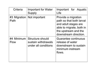
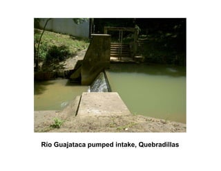
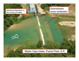
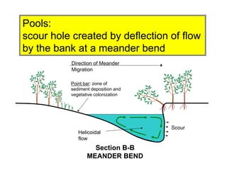
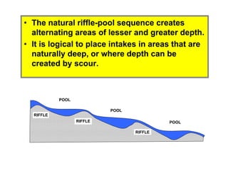
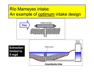
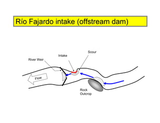
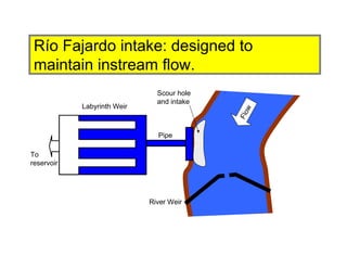
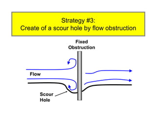
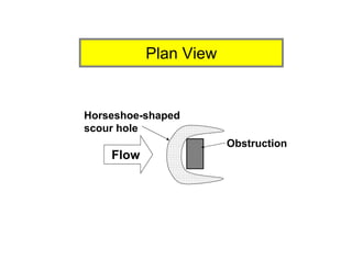
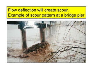
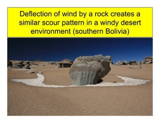
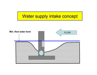
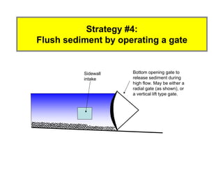
Water Supply Intake Structures
Gregory L. Morris, P.E., Ph.D.
Consultant to DNER Water Plan Office
E N G I N E E R I N G
Overview
• Good intake design requires knowledge of
sediment transport and geomorphic
patterns.
• This presentation illustrates some basic
river patterns associated with instream
structures.
• Several examples of intake design based
on these principles are presented.
The structure should
sustain the transport of
coarse materials along
the stream, and
environmentally-
damaging
maintenance activities
should be avoided.
The structure should
sustain a pool of
adequate depth in
front of the intake,
not accumulate
sediment and debris.
#2 Sustain
Sediment
Transport
Structure should not
promote bank erosion
or other forms of
channel instability.
Structure should be
structurally sound
and not damaged by
floods.
#1
Structural
Stability
Important for Aquatic
Life
Important for Water
Supply
Criteria
Guarantee continuous
release of water
downstream to sustain
minimum instream
flows.
Structure should
sustain withdrawals
under all conditions
#4 Minimum
Flow
Provide a migration
path so that both larval
and adult stages are
able to migrate, both in
the upstream and the
downstream direction.
Not important#3 Migration
Path
Important for Aquatic
Life
Important for Water
Supply
Criteria
Typical Water Supply Intakes
• Consist of low dam which accumulates
sediment on upstream side.
• Prone to clogging by coarse sediment
following floods
• Can act as migration barriers.
Río Guajataca pumped intake, Quebradillas
Río Cañas gravity intake, Miradero FP, Mayagüez.
Flow
Sediment deposition in
the vicinity of intake
Downstream
scour protection
Madre Vieja intake, Puerta Plata, D.R.
Intake design can be improved
by utilizing basic geomorphic
patterns in streams
• Meanders
• This presentation illustrates some basic
river patterns associated with instream
structures.
• Several examples of intake design based
on these principles are presented.
A
A
B
B
Thalweg
Scour & meander migration
Point bar:
deposition
Basic geomorphic patterns in streams
Pools created by scour
Crossing
Flow depth relatively
shallow, no deep pools
Section A-A
CROSSING
Banks generally stable on
both sides, vegetated.
Crossing:
Shallow water, flow parallel to banks
A
A
B
B
Thalweg
Scour & meander migration
Point bar:
deposition
Basic geomorphic patterns in streams
Pools created by scour
Crossing
Point bar: zone of
sediment deposition and
vegetative colonization
Direction of Meander
Migration
Helicoidal
flow
Scour
Section B-B
MEANDER BEND
Pools:
scour hole created by deflection of flow
by the bank at a meander bend
A
A
B
B
Main Current
Point bar:
deposition
Pool created by flow deflection
RIFFLE
POOL
POOL
POOLRIFFLE
RIFFLE
• The natural riffle-pool sequence creates
alternating areas of lesser and greater depth.
• It is logical to place intakes in areas that are
naturally deep, or where depth can be
created by scour.
Strategy #1:
Locate intake in natural pool
• Use existing stable scour pool in the river.
• Typically results in intake being located at
the exterior of a meander bend.
• Should have rock or engineered structure
to insure stability of bankside structures.
Río Mameyes intake:
An example of optimum intake design
Intake Screen
Flow
Intake Screen
Flow
Intake Screen
Flow
Pump
Station
Intake screen
Cross-Section View
Pump
Station
Intake screen
Cross-Section View
Extraction
limited to
5 mgd
Flow
PR-3
Río Mameyes Intake
Río Cañas
Flow
Miradero
Intake
Scour in
front of
intake
Río Grande de Añasco
Miradero intake, Río Añasco
Scour in front of intake
Sediment deposition
in channel
River weir to control bed level
and guarantee minimum flow
Scour in front
of rock
Río Fajardo intake (offstream dam)
Intake
River Weir
Scour
Rock
Outcrop
Flow
Río Fajardo intake (offstream dam)
Scour hole
and intake
Pipe
Labyrinth Weir
To
reservoir
River Weir
Flow
Río Fajardo intake: designed to
maintain instream flow.
Pipe
Scour hole
and intake
River weir
releasing
minimum
instream flow
Diversion weir to water supply
facility set at minimum
instream flow level.
Flow to water supply
reservoir only after
instream flow is exceeded.
Río Fajardo intake: designed to
maintain instream flow.
Backwater zone: greater depth and
lower velocity causes sediment to
deposit upstream of obstruction.
Scour zone: plunging flow creates
localized erosion, while structure
impedes downstream transport of
sediment.
Original
streambed
profile
Scour hole which may threaten
structural integrity of low dam or
roadway
Sediment deposit
upstream of obstruction
Strategy #2: Use flow plunging over an
obstruction which causes scour
Intake area
Scour
Flow
Large
stone for
grade
control
Level control weir
Weir to create
scour hole
Weir for instream
flow release
Río Blanco Intake
Create of a scour hole by overflow
To offstream weir
Scour
Hole
Fixed
Obstruction
Strategy #3:
Create of a scour hole by flow obstruction
Flow
Flow
Horseshoe-shaped
scour hole
Obstruction
Plan View
Flow deflection will create scour.
Example of scour pattern at a bridge pier
Deflection of wind by a rock creates a
similar scour pattern in a windy desert
environment (southern Bolivia)
FLOW
Water supply intake concept
Min. flow water level
Flow
Location of intake in center of the river
has environmental advantages, but
operational disadvantages
INTAKE
Sidewall
intake
Bottom opening gate to
release sediment during
high flow. May be either a
radial gate (as shown), or
a vertical lift type gate.
Strategy #4:
Flush sediment by operating a gate
Rio
Blanco
Tributary
Pump Sta
New Fish Ladder
Concluding Remarks
• Traditional intake designs are not optimal from
either engineering or environmental standpoint.
• Intake design can be greatly improved by
understanding river geomorphology,
• Unfortunately, most engineers have very little, if
any, understanding of river geomorphic
processes.
• There are no standards or guidelines to assist
engineers in designing intakes which are best
for conditions in Puerto Rico.
Thank You
Gregory Morris
gregmorris@attglobal.net
www.gmaeng.com
Profile View
Flood
Level
Riffle
Riffle
Plan View
Pool
Riffle
Pool
Pool
Land figs river structures

Land figs river structures

  • 1.
    Water Supply IntakeStructures Gregory L. Morris, P.E., Ph.D. Consultant to DNER Water Plan Office E N G I N E E R I N G
  • 2.
    Overview • Good intakedesign requires knowledge of sediment transport and geomorphic patterns. • This presentation illustrates some basic river patterns associated with instream structures. • Several examples of intake design based on these principles are presented.
  • 3.
    The structure should sustainthe transport of coarse materials along the stream, and environmentally- damaging maintenance activities should be avoided. The structure should sustain a pool of adequate depth in front of the intake, not accumulate sediment and debris. #2 Sustain Sediment Transport Structure should not promote bank erosion or other forms of channel instability. Structure should be structurally sound and not damaged by floods. #1 Structural Stability Important for Aquatic Life Important for Water Supply Criteria
  • 4.
    Guarantee continuous release ofwater downstream to sustain minimum instream flows. Structure should sustain withdrawals under all conditions #4 Minimum Flow Provide a migration path so that both larval and adult stages are able to migrate, both in the upstream and the downstream direction. Not important#3 Migration Path Important for Aquatic Life Important for Water Supply Criteria
  • 5.
    Typical Water SupplyIntakes • Consist of low dam which accumulates sediment on upstream side. • Prone to clogging by coarse sediment following floods • Can act as migration barriers.
  • 6.
    Río Guajataca pumpedintake, Quebradillas
  • 7.
    Río Cañas gravityintake, Miradero FP, Mayagüez.
  • 8.
    Flow Sediment deposition in thevicinity of intake Downstream scour protection Madre Vieja intake, Puerta Plata, D.R.
  • 9.
    Intake design canbe improved by utilizing basic geomorphic patterns in streams • Meanders • This presentation illustrates some basic river patterns associated with instream structures. • Several examples of intake design based on these principles are presented.
  • 10.
    A A B B Thalweg Scour & meandermigration Point bar: deposition Basic geomorphic patterns in streams Pools created by scour Crossing
  • 11.
    Flow depth relatively shallow,no deep pools Section A-A CROSSING Banks generally stable on both sides, vegetated. Crossing: Shallow water, flow parallel to banks
  • 12.
    A A B B Thalweg Scour & meandermigration Point bar: deposition Basic geomorphic patterns in streams Pools created by scour Crossing
  • 13.
    Point bar: zoneof sediment deposition and vegetative colonization Direction of Meander Migration Helicoidal flow Scour Section B-B MEANDER BEND Pools: scour hole created by deflection of flow by the bank at a meander bend
  • 14.
  • 15.
    RIFFLE POOL POOL POOLRIFFLE RIFFLE • The naturalriffle-pool sequence creates alternating areas of lesser and greater depth. • It is logical to place intakes in areas that are naturally deep, or where depth can be created by scour.
  • 16.
    Strategy #1: Locate intakein natural pool • Use existing stable scour pool in the river. • Typically results in intake being located at the exterior of a meander bend. • Should have rock or engineered structure to insure stability of bankside structures.
  • 17.
    Río Mameyes intake: Anexample of optimum intake design Intake Screen Flow Intake Screen Flow Intake Screen Flow Pump Station Intake screen Cross-Section View Pump Station Intake screen Cross-Section View Extraction limited to 5 mgd
  • 18.
  • 19.
    Río Cañas Flow Miradero Intake Scour in frontof intake Río Grande de Añasco Miradero intake, Río Añasco
  • 20.
    Scour in frontof intake Sediment deposition in channel River weir to control bed level and guarantee minimum flow Scour in front of rock Río Fajardo intake (offstream dam)
  • 21.
  • 22.
    Scour hole and intake Pipe LabyrinthWeir To reservoir River Weir Flow Río Fajardo intake: designed to maintain instream flow.
  • 23.
    Pipe Scour hole and intake Riverweir releasing minimum instream flow Diversion weir to water supply facility set at minimum instream flow level. Flow to water supply reservoir only after instream flow is exceeded. Río Fajardo intake: designed to maintain instream flow.
  • 24.
    Backwater zone: greaterdepth and lower velocity causes sediment to deposit upstream of obstruction. Scour zone: plunging flow creates localized erosion, while structure impedes downstream transport of sediment. Original streambed profile Scour hole which may threaten structural integrity of low dam or roadway Sediment deposit upstream of obstruction Strategy #2: Use flow plunging over an obstruction which causes scour
  • 25.
    Intake area Scour Flow Large stone for grade control Levelcontrol weir Weir to create scour hole Weir for instream flow release Río Blanco Intake Create of a scour hole by overflow To offstream weir
  • 27.
    Scour Hole Fixed Obstruction Strategy #3: Create ofa scour hole by flow obstruction Flow
  • 28.
  • 29.
    Flow deflection willcreate scour. Example of scour pattern at a bridge pier
  • 30.
    Deflection of windby a rock creates a similar scour pattern in a windy desert environment (southern Bolivia)
  • 31.
    FLOW Water supply intakeconcept Min. flow water level
  • 32.
    Flow Location of intakein center of the river has environmental advantages, but operational disadvantages INTAKE
  • 33.
    Sidewall intake Bottom opening gateto release sediment during high flow. May be either a radial gate (as shown), or a vertical lift type gate. Strategy #4: Flush sediment by operating a gate
  • 34.
  • 37.
    Concluding Remarks • Traditionalintake designs are not optimal from either engineering or environmental standpoint. • Intake design can be greatly improved by understanding river geomorphology, • Unfortunately, most engineers have very little, if any, understanding of river geomorphic processes. • There are no standards or guidelines to assist engineers in designing intakes which are best for conditions in Puerto Rico.
  • 38.
  • 41.