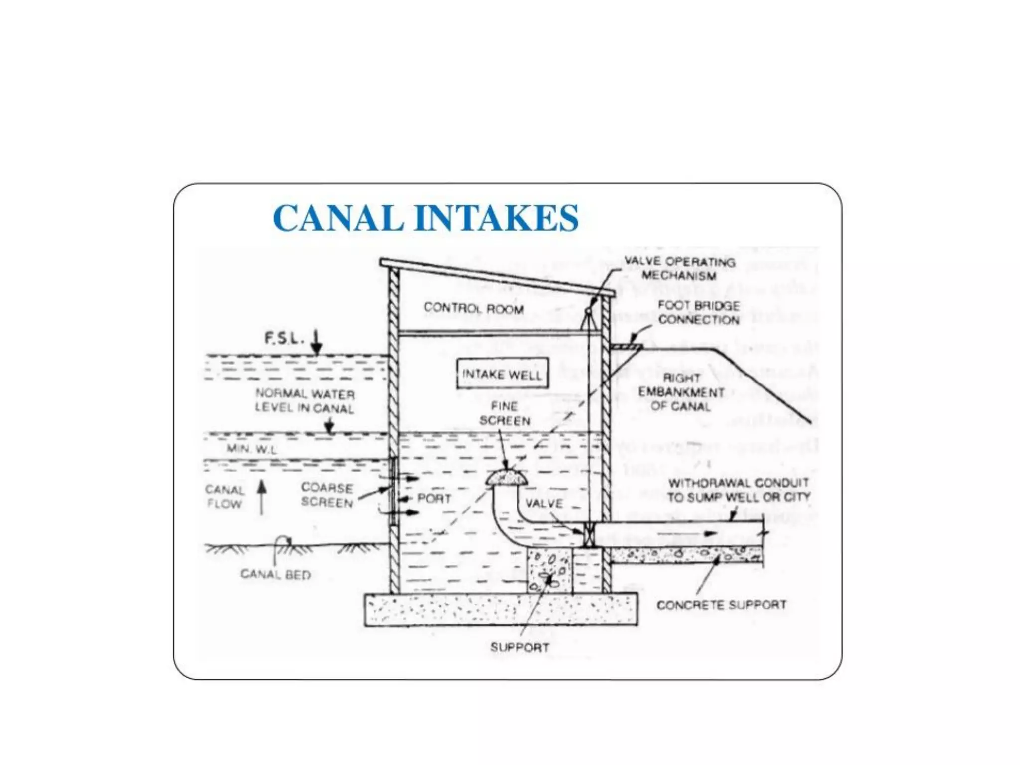
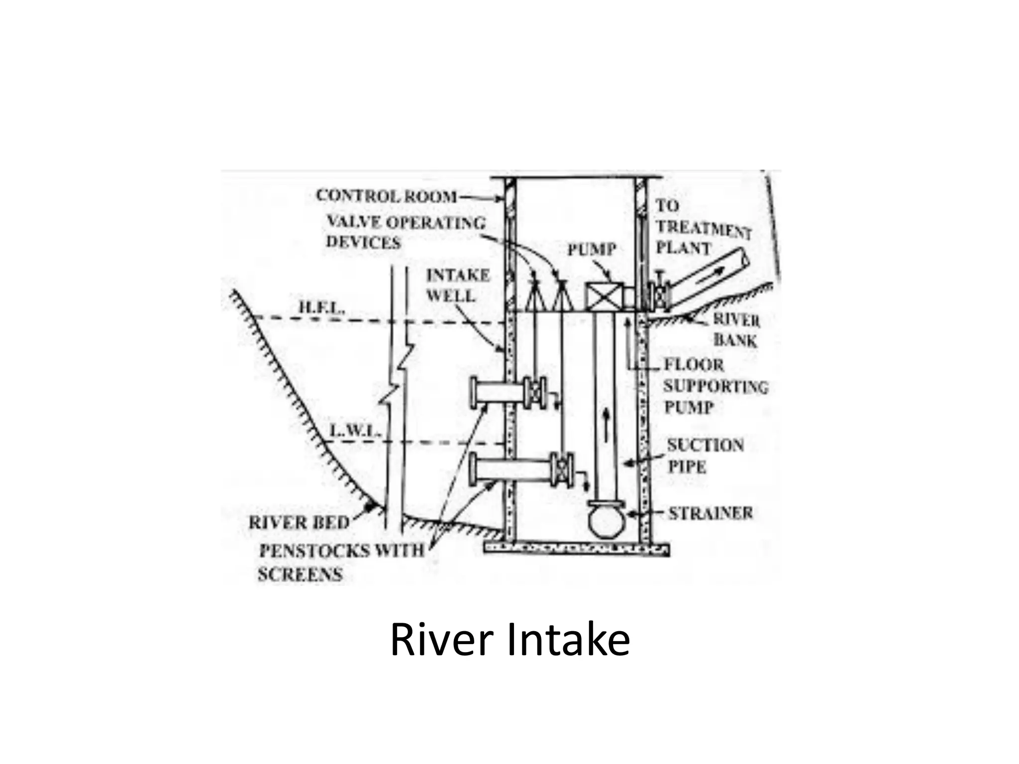
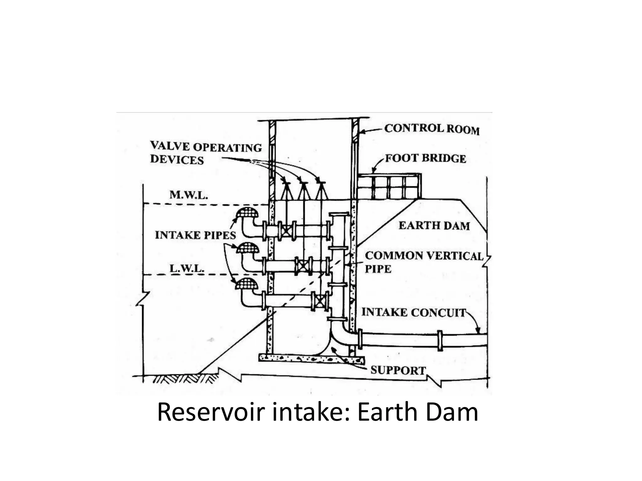
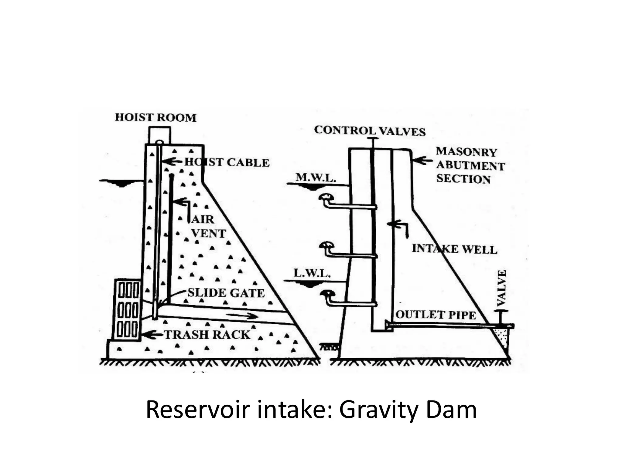
Intake Structures
Unit I
Chapter 2
Definitionof intakes
• A structure placed in a water source to permit the
withdrawal of water from the source and discharge it
into an intake conduit through which it flows to the
treatment plant, or into an intake well from where
water is pumped to treatment plant is called intake.
• Intake consist of two sections First, intake conduit with
the screen at the inlet end and valve to control the
flow of water. Second, a structure permitting the
withdrawal of water from source and housing and
supporting intake conduit, valves, pumps etc.
• The structure may be of stone masonry or
brick masonry, R.C.C, or concrete blocks. The
structure is constructed watertight and is
designed to resist all forces likely to come
upon it including the pressures due to water,
wave action, the wind, floating debris, annual
rainfall, geological formations.
Factors governing the selection of site for the
location of an Intake
1. Site should be as nearer to the treatment plant as
possible, so that cost of conveyance of water is less
2. Located in pure water zone-reduces load on
treatment plant
3. Should not be located at the d/s or in the vicinity of
sewage disposal point
4. As far as possible not located in or near the navigation
channel- may be polluted due to discharge of refuse
and wastes from ships and boat
5. Located so as to ensure the supply of water even
under worst conditions – when water level is min.
sufficient quantity should be available . Thus in the
case of rivers, intake should be located in deep
waters, sufficiently away from coast line
6. There is sufficient scope for future expansion
7. Should remain easily accessible even during floods
and it should not be flooded
8. Well connected by good approach road
9. Sit should be free from the attacks of heavy currents
Design considerations
a) Reliability of operation:
Intake should ensure safety of design & reliability of
operation. A failure here would mean shutting off,
of entire supply
a) Quality of water:
Located carefully to obtain best quality of water;
In large rivers this should preferably submerged and
several meters above to bed level to prevent entry of
silt;
In areas of large variations in water level, intake should
be so located to draw water from several depths, so
that excess of turbidity & microorganisms are
prevented from entering the conduit;
Far off from settlement, sewage disposal points and
other pollution sources
c. Structural strength:
Strong enough to resist such forces as caused by
floods, impact of boats, floating debris etc.
d. Economy of construction:
If intake conduit is short, it may be merely an
extension of suction side of the pump
If however, too long, it would be advisable to
interpose a wet well or chamber near the pumps
and draw water from there, instead of having a
long suction pipe.
The latter arrangement may prove to be
comparatively costly involving greater head losses
Types of intakes:
1. Based on no of ports:
Single port & multiple ports
2. Based on source of supply:
Canal intake, river intake, reservoir intake
and lake intake
3. Based on location:
Submerged intake & exposed intake
4. Based on intake condition:
Dry intake & wet intake
Important Features:
• Canal intake is comparatively a simpler arrangement
consisting of a brick-masonry chamber built particularly in
canal bank.
• It has side opening fitted with coarse screen which excludes
floating matter, silt etc from entering the intake well.
• Withdrawal conduit is covered with a fine screen to avoid
entry of silt, sand etc, into the conduit.
• The entry of water is controlled by gate valves which is
operated from top.
• Pitching on both U/S & D/S to avoid scouring as it reduces
the area and velocity of water is increased.
• Wet well type – single port
Coarse screen: MS bars – 15 to 20 mm dia
• Opening : 25 to 50 mm
• Flow velocity: 0.15 m/s or less
Fine screen: Wire mesh type
• Opening size: 6mm x 6 mm or less
• Velocity: 0.3 m/s
Intake conduit (withdrawal conduit): Flow velocity –
1.0 to 1.5 m/s
River Intake
Important features:
• Wet well type – multiple ports
• It is the structure constructed with an objective of
withdrawing water from the rivers.
• It is generally constructed when water is required in
large amount for a large community.
• River intakes are so located that even during the low
water level in the river water remains available at the
intake in sufficient quantity.
• It consists of masonry or RCC inlet tower which is
provided with several inlets called penstocks.
• The penstocks are provided with valves to control
the entry of water through them.
• The penstocks are provided at different water
levels to permit the withdrawal of water when
the water level in the river drops.
• The penstocks discharge water into intake tower.
Pumping is required when the level of intake is
lower than community.
Reservoir intake: Earth Dam
Reservoir intake: Gravity Dam
Important Features
• In the case of the reservoir, the type of intake to be
provided depends on the type of dam constructed to
create the reservoir.
• The reservoir intake for gravity dam consists of an
intake conduit or intake well constructed within the
dam itself
• In the case of a reservoir created by constructing an
earth dam, the intake consists of a masonry or R.C.C
intake tower (or intake well) placed near the upstream
toe of the dam. The intake tower is connected to the
top of the dam by a foot bridge.
Key feature of intake for earth dam
• The intake pipes are at different levels with the common
vertical pipe.
• The intake pipe has the fine screen to permit entry of clear
water.
• Pipes at different levels maintain continuous withdrawal of
water from the of reservoir.
• Intake pipes are provided with valves to control the flow of
water.
• The control room is at the top to operate valves.
• Common vertical pipe enters the conduit which carries
water to the treatment plant.
• The dry intake tower has pipes fitted inside.

part ii_intake structures

  • 1.
  • 2.
    Definitionof intakes • Astructure placed in a water source to permit the withdrawal of water from the source and discharge it into an intake conduit through which it flows to the treatment plant, or into an intake well from where water is pumped to treatment plant is called intake. • Intake consist of two sections First, intake conduit with the screen at the inlet end and valve to control the flow of water. Second, a structure permitting the withdrawal of water from source and housing and supporting intake conduit, valves, pumps etc.
  • 3.
    • The structuremay be of stone masonry or brick masonry, R.C.C, or concrete blocks. The structure is constructed watertight and is designed to resist all forces likely to come upon it including the pressures due to water, wave action, the wind, floating debris, annual rainfall, geological formations.
  • 4.
    Factors governing theselection of site for the location of an Intake 1. Site should be as nearer to the treatment plant as possible, so that cost of conveyance of water is less 2. Located in pure water zone-reduces load on treatment plant 3. Should not be located at the d/s or in the vicinity of sewage disposal point 4. As far as possible not located in or near the navigation channel- may be polluted due to discharge of refuse and wastes from ships and boat
  • 5.
    5. Located soas to ensure the supply of water even under worst conditions – when water level is min. sufficient quantity should be available . Thus in the case of rivers, intake should be located in deep waters, sufficiently away from coast line 6. There is sufficient scope for future expansion 7. Should remain easily accessible even during floods and it should not be flooded 8. Well connected by good approach road 9. Sit should be free from the attacks of heavy currents
  • 6.
    Design considerations a) Reliabilityof operation: Intake should ensure safety of design & reliability of operation. A failure here would mean shutting off, of entire supply a) Quality of water: Located carefully to obtain best quality of water; In large rivers this should preferably submerged and several meters above to bed level to prevent entry of silt; In areas of large variations in water level, intake should be so located to draw water from several depths, so that excess of turbidity & microorganisms are prevented from entering the conduit; Far off from settlement, sewage disposal points and other pollution sources
  • 7.
    c. Structural strength: Strongenough to resist such forces as caused by floods, impact of boats, floating debris etc. d. Economy of construction: If intake conduit is short, it may be merely an extension of suction side of the pump If however, too long, it would be advisable to interpose a wet well or chamber near the pumps and draw water from there, instead of having a long suction pipe. The latter arrangement may prove to be comparatively costly involving greater head losses
  • 8.
    Types of intakes: 1.Based on no of ports: Single port & multiple ports 2. Based on source of supply: Canal intake, river intake, reservoir intake and lake intake 3. Based on location: Submerged intake & exposed intake 4. Based on intake condition: Dry intake & wet intake
  • 10.
    Important Features: • Canalintake is comparatively a simpler arrangement consisting of a brick-masonry chamber built particularly in canal bank. • It has side opening fitted with coarse screen which excludes floating matter, silt etc from entering the intake well. • Withdrawal conduit is covered with a fine screen to avoid entry of silt, sand etc, into the conduit. • The entry of water is controlled by gate valves which is operated from top. • Pitching on both U/S & D/S to avoid scouring as it reduces the area and velocity of water is increased.
  • 11.
    • Wet welltype – single port Coarse screen: MS bars – 15 to 20 mm dia • Opening : 25 to 50 mm • Flow velocity: 0.15 m/s or less Fine screen: Wire mesh type • Opening size: 6mm x 6 mm or less • Velocity: 0.3 m/s Intake conduit (withdrawal conduit): Flow velocity – 1.0 to 1.5 m/s
  • 12.
  • 13.
    Important features: • Wetwell type – multiple ports • It is the structure constructed with an objective of withdrawing water from the rivers. • It is generally constructed when water is required in large amount for a large community. • River intakes are so located that even during the low water level in the river water remains available at the intake in sufficient quantity.
  • 14.
    • It consistsof masonry or RCC inlet tower which is provided with several inlets called penstocks. • The penstocks are provided with valves to control the entry of water through them. • The penstocks are provided at different water levels to permit the withdrawal of water when the water level in the river drops. • The penstocks discharge water into intake tower. Pumping is required when the level of intake is lower than community.
  • 15.
  • 16.
  • 17.
    Important Features • Inthe case of the reservoir, the type of intake to be provided depends on the type of dam constructed to create the reservoir. • The reservoir intake for gravity dam consists of an intake conduit or intake well constructed within the dam itself • In the case of a reservoir created by constructing an earth dam, the intake consists of a masonry or R.C.C intake tower (or intake well) placed near the upstream toe of the dam. The intake tower is connected to the top of the dam by a foot bridge.
  • 18.
    Key feature ofintake for earth dam • The intake pipes are at different levels with the common vertical pipe. • The intake pipe has the fine screen to permit entry of clear water. • Pipes at different levels maintain continuous withdrawal of water from the of reservoir. • Intake pipes are provided with valves to control the flow of water. • The control room is at the top to operate valves. • Common vertical pipe enters the conduit which carries water to the treatment plant. • The dry intake tower has pipes fitted inside.