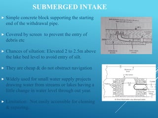
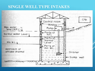
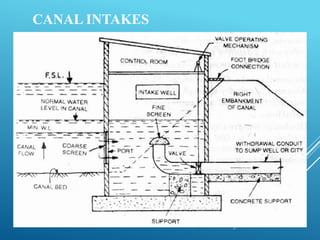
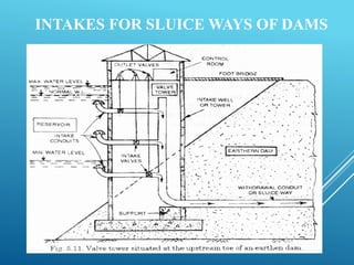
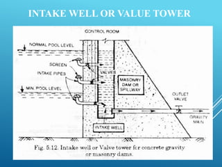
INTAKE
STRUCTURES
A.C.HARJEETH EDBERT
311520103010
WHAT IS AN INTAKE STRUCTURE ?
 The basic function of intake structure is to help in safely
withdrawing water from the source and then to discharge this
water in to the withdrawal conduit, through which it reaches
the water treatment plant.
 It is constructed at the entrance of the withdrawal pipe and
thereby protecting it from being clogged by debris.
 Some times from reservoirs where gravity flow is possible, water
is directly transmitted to the treatment through intake structure.
 If gravity flow is not possible, water entering intake structure is
lifted by pumps and taken to the treatment plant.
SELECTING LOCATION OF INTAKE
STRUCTURE
 Site should be near the treatment plant to reduce conveyance
cost.
 Intake must be located in the purer zone of the source so that
best quality water is withdrawn from source to reduce the load on
the treatment plant.
 Intake must never be located in the vicinity of waste water
disposal point.
 Intake must never be located near the navigation channels so as
to reduce chances of pollution due to waste discharge from
ships.
 The site should be such as to permit greater withdrawal of water, if
required in future.
SELECTING LOCATION OF INTAKE
STRUCTURE
 Intake must be located at a place from where it can draw
water even during the driest period of the year.
 The intake site should remain easily accessible during floods
and should not get flooded.
 In meandering rivers, the intakes should not be located on
curves or atleast on sharp curves.
TYPES OF INTAKES
 Simple Submerged Intakes
 Intake Towers
 Medium Sized River Intake Structures
 Canal Intakes
 Intakes for sluice ways of dams
SUBMERGED INTAKE
SUBMERGED INTAKE
 Simple concrete block supporting the starting
end of the withdrawal pipe.
 Covered by screen to prevent the entry of
debris etc
 Chances of siltation: Elevated 2 to 2.5m above
the lake bed level to avoid entry of silt.
 They are cheap & do not obstruct navigation
 Widely used for small water supply projects
drawing water from streams or lakes having a
little change in water level through out year.
 Limitation: Not easily accessible for cleaning
& repairing.
INTAKE TOWERS
 They are widely used on large water supply projects drawing water
from rivers or reservoirs having large change in water level.
 Gate controlled openings called Ports are provided at various levels
in these concrete towers to regulate the flow.
 If the entry ports are submerged at all levels, there is no problem of
any clogging or damage by debris etc.
 There are two major types of intake towers:
(a) Wet intake towers
(b) Dry intake towers
DRY INTAKE TOWERS
 The water is directly drawn in to the withdrawal conduit
through the gated entry ports.
 It has no water inside the tower if its gates are closed.
 When the entry ports are closed, a dry intake tower will be
subjected to additional buoyant forces.
 Hence it must be of heavier construction than wet intake
tower.
 They are useful since water can be withdrawn from any
selected level of the reservoir by opening the port at that
level.
DRY INTAKE TOWERS
WET INTAKE TOWERS
 It consist of a concrete circular shell filled with water up to the
reservoir level and has a vertical inside shaft which is
connected to the withdrawal pipe.
 The withdrawal pipe may lie over the bed of the rivers or may
be in the form of tunnels below the river bed.
 Openings are made in to the outer concrete shell as well as,
in to the inside shaft.
 Gates are usually placed on the shaft, so as to control the
flow of water in to the shaft and the withdrawal conduit.
 The water coming out of the withdrawal pipe may be taken
to pump house for lift (if treatment plant is at high elevation)
or may be directly taken to treatment plant (at lower
elevation).
WET INTAKE TOWERS
MEDIUM SIZED RIVER INTAKE STRUCTURES
 They are generally constructed for withdrawing water from
almost all rivers.
 They can be classified in to two types
(1) Twin well type of intake structure
(2) Single well type of intake structure
TWIN WELL TYPE INTAKES
 They are constructed on almost all types of rivers, where the river water hugs the river
bank.
 A typical river intake structure consists of 3 components:
(a) An inlet well
(b) An inlet pipe (intake pipe)
(c) A jack well
 Inlet well is usually circular in c/s, made of masonry or concrete.
 Inlet pipe connects inlet well with jack well. It has a min dia of 45cm, laid at slope of 1 in
200. Flow velocity through it<1.2m/s
 Water entering jack well is lifted by pumps & fed into the rising main
 Jack well should be founded on hard strata having B.C> 450 kN/m2.
TWIN WELL TYPE INTAKES
SINGLE WELL TYPE INTAKES
 No inlet well & inlet pipe in this type of river intake.
 Opening or ports fitted with bar screens are provided in the
jack well itself.
 The sediment entering will usually be less, since clearer water
will enter the off-take channel.
 The silt entering the jack well will partly settle down in the
bottom silt zone of jack well or may be lifted up with the
pumped water since pumps can easily lift sedimented water.
 The jack well can be periodically cleaned manually, by
stopping the water entry in to the well.
SINGLE WELL TYPE INTAKES
CANAL INTAKES
INTAKES FOR SLUICE WAYS OF DAMS
INTAKE WELL OR VALUE TOWER
VALUE TOWER IN EARTHEN DAM
THANK YOU !

INTAKE TOWERS.pdf

  • 1.
  • 2.
    WHAT IS ANINTAKE STRUCTURE ?  The basic function of intake structure is to help in safely withdrawing water from the source and then to discharge this water in to the withdrawal conduit, through which it reaches the water treatment plant.  It is constructed at the entrance of the withdrawal pipe and thereby protecting it from being clogged by debris.  Some times from reservoirs where gravity flow is possible, water is directly transmitted to the treatment through intake structure.  If gravity flow is not possible, water entering intake structure is lifted by pumps and taken to the treatment plant.
  • 3.
    SELECTING LOCATION OFINTAKE STRUCTURE  Site should be near the treatment plant to reduce conveyance cost.  Intake must be located in the purer zone of the source so that best quality water is withdrawn from source to reduce the load on the treatment plant.  Intake must never be located in the vicinity of waste water disposal point.  Intake must never be located near the navigation channels so as to reduce chances of pollution due to waste discharge from ships.  The site should be such as to permit greater withdrawal of water, if required in future.
  • 4.
    SELECTING LOCATION OFINTAKE STRUCTURE  Intake must be located at a place from where it can draw water even during the driest period of the year.  The intake site should remain easily accessible during floods and should not get flooded.  In meandering rivers, the intakes should not be located on curves or atleast on sharp curves.
  • 5.
    TYPES OF INTAKES Simple Submerged Intakes  Intake Towers  Medium Sized River Intake Structures  Canal Intakes  Intakes for sluice ways of dams
  • 6.
  • 7.
    SUBMERGED INTAKE  Simpleconcrete block supporting the starting end of the withdrawal pipe.  Covered by screen to prevent the entry of debris etc  Chances of siltation: Elevated 2 to 2.5m above the lake bed level to avoid entry of silt.  They are cheap & do not obstruct navigation  Widely used for small water supply projects drawing water from streams or lakes having a little change in water level through out year.  Limitation: Not easily accessible for cleaning & repairing.
  • 8.
    INTAKE TOWERS  Theyare widely used on large water supply projects drawing water from rivers or reservoirs having large change in water level.  Gate controlled openings called Ports are provided at various levels in these concrete towers to regulate the flow.  If the entry ports are submerged at all levels, there is no problem of any clogging or damage by debris etc.  There are two major types of intake towers: (a) Wet intake towers (b) Dry intake towers
  • 9.
    DRY INTAKE TOWERS The water is directly drawn in to the withdrawal conduit through the gated entry ports.  It has no water inside the tower if its gates are closed.  When the entry ports are closed, a dry intake tower will be subjected to additional buoyant forces.  Hence it must be of heavier construction than wet intake tower.  They are useful since water can be withdrawn from any selected level of the reservoir by opening the port at that level.
  • 10.
  • 11.
    WET INTAKE TOWERS It consist of a concrete circular shell filled with water up to the reservoir level and has a vertical inside shaft which is connected to the withdrawal pipe.  The withdrawal pipe may lie over the bed of the rivers or may be in the form of tunnels below the river bed.  Openings are made in to the outer concrete shell as well as, in to the inside shaft.  Gates are usually placed on the shaft, so as to control the flow of water in to the shaft and the withdrawal conduit.  The water coming out of the withdrawal pipe may be taken to pump house for lift (if treatment plant is at high elevation) or may be directly taken to treatment plant (at lower elevation).
  • 12.
  • 13.
    MEDIUM SIZED RIVERINTAKE STRUCTURES  They are generally constructed for withdrawing water from almost all rivers.  They can be classified in to two types (1) Twin well type of intake structure (2) Single well type of intake structure
  • 14.
    TWIN WELL TYPEINTAKES  They are constructed on almost all types of rivers, where the river water hugs the river bank.  A typical river intake structure consists of 3 components: (a) An inlet well (b) An inlet pipe (intake pipe) (c) A jack well  Inlet well is usually circular in c/s, made of masonry or concrete.  Inlet pipe connects inlet well with jack well. It has a min dia of 45cm, laid at slope of 1 in 200. Flow velocity through it<1.2m/s  Water entering jack well is lifted by pumps & fed into the rising main  Jack well should be founded on hard strata having B.C> 450 kN/m2.
  • 15.
  • 16.
    SINGLE WELL TYPEINTAKES  No inlet well & inlet pipe in this type of river intake.  Opening or ports fitted with bar screens are provided in the jack well itself.  The sediment entering will usually be less, since clearer water will enter the off-take channel.  The silt entering the jack well will partly settle down in the bottom silt zone of jack well or may be lifted up with the pumped water since pumps can easily lift sedimented water.  The jack well can be periodically cleaned manually, by stopping the water entry in to the well.
  • 17.
  • 18.
  • 19.
    INTAKES FOR SLUICEWAYS OF DAMS
  • 20.
    INTAKE WELL ORVALUE TOWER
  • 21.
    VALUE TOWER INEARTHEN DAM
  • 22.