Booking open Available Pune Call Girls Pargaon 6297143586 Call Hot Indian Gi...
Chapter 4 design of hydropower plants.pdf
1. Hydropower Engineering Instructor: Mekete Dessie (PhD)
Faculty of Civil & Water Resource
Engineering
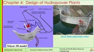
Chapter 4: Design of Hydropower Plants
Tekeze 3D model
Arch Dam upstream view
2. Hydropower Engineering Instructor: Mekete Dessie (PhD)
Faculty of Civil & Water Resource
Engineering
Design of Civil Structures
Intakes
• The intake structure (or head regulator) is a hydraulic device
constructed at the head of power canal, or a tunnel conduit
through which water is withdrawn from the reservoir.
• In high-head structures the intake can be either an integral
part of a dam or separate;
• In the form of a tower with entry ports at various levels
which may aid flow regulation when there is a wide range of
fluctuations of reservoir water level.
3. Hydropower Engineering Instructor: Mekete Dessie (PhD)
Faculty of Civil & Water Resource
Engineering
Functions of Intakes
• To control flow of water in to the conveyance system. The control is achieved by a
gate or a valve.
• To provide smooth, easy and vortex or turbulence free entry of water in the
conveyance system which is to minimize head loss.
• To prevent entry of coarse river born trash matter such as boulders, logs, tree
branches etc.
• To exclude heavy sediment load of the river from entering the conveyance system.
Types of Intakes
• Run -of -river intakes
• Dam intakes
• Tower intakes
• Shaft intakes
• Intakes of special type
4. Hydropower Engineering Instructor: Mekete Dessie (PhD)
Faculty of Civil & Water Resource
Engineering
Run -of -river intakes
These are low head intakes
which lead water into the
diversion canals.
•The inlet invert level of the
intake is raised to form a sill so
as to prevent entry of rolling
bed load into the canal
•A skimmer wall (a diaphragm
which extends below the water
surface) abstracts the floating
material from interring into the
canal
•Trash rack is provided at the
entrance and may be equipped
with either manual or automatic
power-driven rack cleaning
devices
5. Hydropower Engineering Instructor: Mekete Dessie (PhD)
Faculty of Civil & Water Resource
Engineering
An intake structure leads river water into a waterway, and is designed to meet the
following conditions.
• The maximum plant discharge is taken in constantly and is adjusted as required.
• The head loss is small.
• Inflow is smooth and does not have any air intrusion vortex
• Sediment, driftwood, leaves, etc. do not flow into the intake.
• The intake is not susceptible to damage due to flooding or landslide.
• Maintenance work after completion is easily carried out.
Location and Orientation of Run -of -river intakes
The following criteria should
be observed to achieve the
above objectives:
7. Hydropower Engineering Instructor: Mekete Dessie (PhD)
Faculty of Civil & Water Resource
Engineering
• The secondary current near the bed,
transports sediment away from the region
and draws in water from the top layers
where the sediment concentration is
relatively low.
• Since the sediment concentration is
highest at the bed the water diversion
structure should be located where the
flow near the bed is away from the intake.
• Such conditions occur at river bends
where the spiral (helicoidal) current
carries sediment towards the inner bank
away from the outer bank.
• In straight channel reaches an artificial
bend, a groyne island or guide vanes
may be designed to cause the required
curvature of flow
Use of
artificial
groyne (e.g.
island) to
induce
desired
curvature to
flow at
intakes
Guide vanes
layouts
upstream of
intake for
sediment
exclusion
8. Hydropower Engineering Instructor: Mekete Dessie (PhD)
Faculty of Civil & Water Resource
Engineering
Dam intakes
• For valley dam plants, the intake structure
is provided usually in the body of the dam;
• The penstocks are embodied in the dam
• The main features of such an intake are:
a trash rack structure in front of the
dam,
a bell mouth inlet horizontal or inclined
alignment,
control gate installed either at or after
the bell mouth,
Cage-shaped intakes resting against
the face of the dam and supported on
slab cantilevered from the dam provide
larger area of entry than the penstock
intake area thus reducing entrance losses
10. Hydropower Engineering Instructor: Mekete Dessie (PhD)
Faculty of Civil & Water Resource
Engineering
• The most common type of intake structure is
the vertical structure, generally referred to as
a free-standing intake tower.
• It allows increased flexibility when locating the
outlet works at the site.
• The vertical tower is usually more economical
and easier to layout than the inclined intake
structure.
• Conduits and openings, operating equipment,
and access features lend themselves more
readily to arrangement in the vertical
structure.
• A service bridge provides access to the top of
the structure.
Free-standing/ Tower intake structure
11. Hydropower Engineering Instructor: Mekete Dessie (PhD)
Faculty of Civil & Water Resource
Engineering
Inclined intake structure
• For higher embankment dams in high seismic
risk areas where a vertical structure may not be
feasible, an inclined intake structure supported
against the abutment is an alternative for
consideration.
• An inclined structure has the advantage of increased
stability over a vertical structure.
• In high seismic locations and on steep abutment
slopes, anchoring of the structure to the abutment to
maintain stability and prevent liftoff should be
investigated.
Intake structures fall into three general types
(a) inclined intake on a sloping embankment; (b)
freestanding intake tower, usually incorporated into
the flood control outlet facilities of embankment
dams; and (c) face-of-dam intake, constructed as an
integral part of the vertical upstream face of a
concrete dam
12. Hydropower Engineering Instructor: Mekete Dessie (PhD)
Faculty of Civil & Water Resource
Engineering
Design of intakes
• There are no standard designs for intake structures.
• Each design is unique and may take on many forms and variations.
• Design depends on a number of considerations including site conditions, economics,
and effectiveness in meeting project requirements.
• Project requirements can include reservoir operating range, drawdown frequency,
discharge range, trash conditions and required frequency of intake cleaning, water
quality, and environmental requirements such as fish passage.
• It is designed such that the following points are complied, as far as possible:
There should be minimum head loss as water enters from the reservoir behind a
dam or the pool behind a barrage into the water conducting system.
There should not be any formation of vortices that could draw air into the water
conducting system.
There should be minimum entry of sediment into the water conducting system.
Floating material should not enter the water conducting system.
13. Hydropower Engineering Instructor: Mekete Dessie (PhD)
Faculty of Civil & Water Resource
Engineering
Design considerations and criteria
The intake structure size and configuration are based on:
• wells size,
• control gate passages,
• inlet hydraulic configuration,
• exit passages, and
• clearance requirements for the mechanical and electrical equipment.
Design criteria
Water levels
• The intake structures should be designed in order to function for different water levels.
• The efficiency of the structure should be checked for the normal and extreme levels.
Placement distance
• The distance between the intake structure and the powerhouse increases the hydraulic losses
and increases the cost of the conveyance structures.
• Thus , most of the powerhouses should be constructed near the dam or the diversion structure in
order save water head, while the intake structures is placed on the lowest point of the reservoirs.
14. Hydropower Engineering Instructor: Mekete Dessie (PhD)
Faculty of Civil & Water Resource
Engineering
Geology
• The intake should be located in a reach of river where the bank is stable
• If possible, the intake should be located at a site possessing
• favorable foundation conditions to minimize costly treatment.
Diverted flow orientation
• Intakes are generally oriented to minimize separation of flow and formation of swirl,
eddies, and vorticity which may entrain air.
• Where the rate of withdrawal is small and the intake mouth is relatively deeply
submerged, flow separation, vorticity, and air entrainment are less likely to occur.
Sediment
• Intakes in reservoirs should be placed above the computed sediment deposit of the
design period of the structure.
• Sediment accumulation in the intake approach causes higher approach velocities,
increased head losses, and flow separation.
• The passage of sediment through the unit may result in wear of the turbine runner
•
15. Hydropower Engineering Instructor: Mekete Dessie (PhD)
Faculty of Civil & Water Resource
Engineering
Siting
Selection of the location for an intake structure depends on:
• foundation conditions,
• alignment of conduit, and
• tunnel access.
• For an embankment dam, the structure is often located adjacent to a hillside into
which the outlet works pass.
• A cut-and-cover-conduit, the structure is generally located at the upstream toe of the
embankment dam.
Locations of control gates
• The control gates are usually located in the intake structure, in a shaft or gate chamber.
• Under special conditions, the control gates may be located at the downstream end of a
pressure tunnel.
16. Hydropower Engineering Instructor: Mekete Dessie (PhD)
Faculty of Civil & Water Resource
Engineering
Control gates at upstream end
• When the gates are placed at the upstream end of the outlet works, the emergency
gates, bulkheads, service gates, and trash rack are all combined into a single
structure.
• Closing of the gates allows for inspection and repair of the entire tunnel and to
readily removing accumulated trash, sediment, or other deposits.
• A disadvantage with upstream control gates is the cost of extending the structure
above the pool and requiring an access bridge.
Intake structure shape
Rectangular
• Are more functional for low-head reservoirs that are designed for large discharges.
• Provide for more efficient layout of entrances and openings, gates and operating
equipment, and other features.
• Rectangular intake structures are usually more easily constructed and site-
adaptable.
17. Hydropower Engineering Instructor: Mekete Dessie (PhD)
Faculty of Civil & Water Resource
Engineering
Intake structure shape
Circular
• Circular intake structures are
structurally more efficient,
providing economic savings,
particularly in high-head projects.
• The lower section of the structure
may be rectangular to provide
arrangement of the water intakes,
trash racks, and bulkheads.
Octagonal
• The tower cross-section can also be of an octagonal shape.
Irregular
• An irregular design may result in the development of very complex and unusual
shapes.
18. Hydropower Engineering Instructor: Mekete Dessie (PhD)
Faculty of Civil & Water Resource
Engineering
Intake towers
Wet intake tower
• A Wet intake is a type of intake tower in which water level in the tower is the same as
the reservoir water level and has a vertical inside shaft connected to the withdrawal
conduit
• Opening s are made into the outer concrete shell as well as into the inside shaft
Dry intake tower
• Water enters through entry port directly into the conveyance
• When the entry ports are closed, a dry intake tower will be subjected to additional
buoyant forces
• Hence it must be of heavier construction than wet intake tower
• Costlier than wet intake since it is heavy to balance buoyant force acting on it.
• Its main advantage that water can be withdrawn from any selected level.
20. Hydropower Engineering Instructor: Mekete Dessie (PhD)
Faculty of Civil & Water Resource
Engineering
Intake Tower Design Considerations
• After all the purposes of the project are established and the functions and criteria for the
outlet works have been clearly defined, the geometry and layout of the intake tower can
proceed.
• Multiple alternatives should be developed and evaluated to determine the optimum plan.
Tower Intakes Shaft Intake
21. Hydropower Engineering Instructor: Mekete Dessie (PhD)
Faculty of Civil & Water Resource
Engineering
Setup
• The entrance floor will hold all the gate lifts including electrical motors, the
instrumentation terminals, cranes, working space, storing space, etc.
• The water supply from the intake tower will be started only after the water level is well
be above the lower 3 gates, which will be then opened and the tower allowed to fill
with water to ensure that the water impact is minimum on the floor and walls of the
tower.
Shaft/ Glory Hole intake
• This is a vertical or a near-vertical shaft, driven at the reservoir site that carries water to
the penstock tunnel reservoir site that carries water to the penstock tunnel feeding the
power house.
• Vertical intakes are commonly used where there is a great difference in elevation
between the reservoir bottom at the intake and the turbine, and where the penstock or
power tunnel is vertical for some distance to the level of the powerhouse.
• The dimensions of the vertical intake are conditioned from the penstock diameter or the
power tunnel diameter.
• This diameter is determined from the comparison of the energy proficiency to the
construction cost.
22. Hydropower Engineering Instructor: Mekete Dessie (PhD)
Faculty of Civil & Water Resource
Engineering
• The main criteria for the structural dimensioning is the minimization of the hydraulic
losses and the avoidance of eddies.
Shaft/ Glory Hole intake
24. Hydropower Engineering Instructor: Mekete Dessie (PhD)
Faculty of Civil & Water Resource
Engineering
Conduit entrance
• In most cases conduit entrance should be rounded or bell mouthed to reduce
hydraulic entrance losses.
• If square-edged entrance is provided separation of flow is more likely to take place
and the consequent danger of cavitation.
25. Hydropower Engineering Instructor: Mekete Dessie (PhD)
Faculty of Civil & Water Resource
Engineering
Control gates
• The control gates located in each gated passage to the outlet tunnel or conduit
generally consist of an emergency gate followed by a service gate.
Service gates
• Service gates are used for flow regulation, and one gate is required for each water
passage.
• For low-and medium-head conditions, the type of gate may be a tractor (mechanically
or hydraulically operated), hydraulically operated slide gate, or hydraulically operated
tainter gate.
• For high-head conditions, hydraulically operated slide gates are generally preferred for
long periods of operation at partial gate openings.
Emergency gates
• Emergency gates should be located within the intake structure immediately upstream
of the service gates.
• Emergency gates are required in reservoirs having water conservation, power, or a
similar type pool to prevent loss of stored water if a service gate is inoperable.
• Emergency gates must be designed to withstand the maximum reservoir head.
26. Hydropower Engineering Instructor: Mekete Dessie (PhD)
Faculty of Civil & Water Resource
Engineering
Trash Racks
Velocity Through Trash Racks
Velocity should be sufficiently low to avoid high
head loss and should be sufficiently high to avoid
large intake and trash rack cross section. The
following are suggested limiting entrance velocities:
31. Hydropower Engineering Instructor: Mekete Dessie (PhD)
Faculty of Civil & Water Resource
Engineering
Skimmer wall
• A skimmer wall is an obstruction placed at the water surface, usually at an angle to the
stream flow which skims floating debris from the passing water.
• If the water level changes markedly as, for example, at the intake of stream, the
skimmer can be a floating piece of timber secured at both ends.
• If changes in water level are small, a fixed skimmer can be used.
• Because some debris usually passes under the skimmer, a trash rack is still
necessary.
• Skimmer walls are made, for the most part, of reinforced concrete with a service
bridge on top.
• They are designed usually for a horizontal pressure of 1000 kg/m2 acting on the
submerged surface.