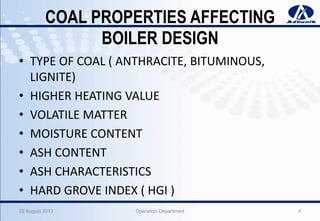
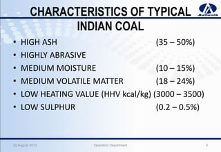
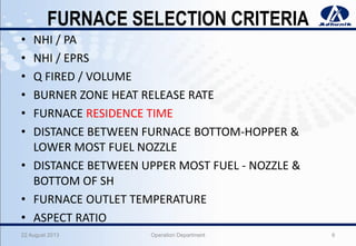
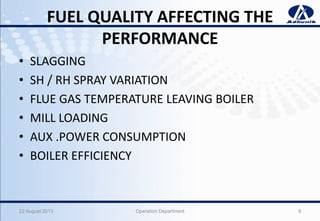
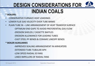
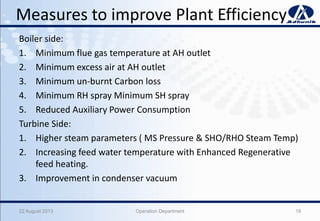
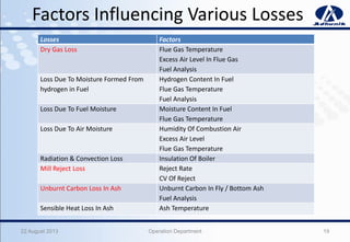
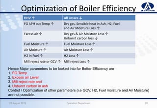
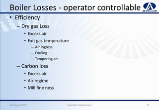
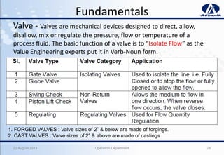
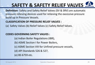
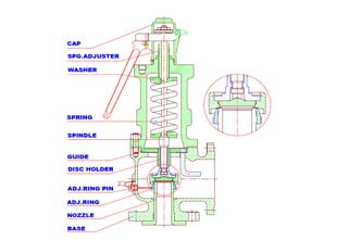
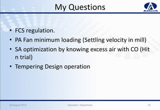
POWER
Boiler Performance & Life
Extension
By – Keyur Patel. (Operation Department)
Topics covered under BHEL program are following
• Boiler Performance & design.
• Life Assessment of Boilers.
• Combustion Optimization & performance.
• Replication & Metallurgical Evolution.
• Water Chemistry.
• O&M of C&I – on Boiler.
• O&M of Valves.
• Field Problems & case Studies in Boilers.
222 August 2013 Operation Department
22 August 2013 Operation Department 3
Boiler Performance & design.
COAL PROPERTIES AFFECTING
BOILER DESIGN
• TYPE OF COAL ( ANTHRACITE, BITUMINOUS,
LIGNITE)
• HIGHER HEATING VALUE
• VOLATILE MATTER
• MOISTURE CONTENT
• ASH CONTENT
• ASH CHARACTERISTICS
• HARD GROVE INDEX ( HGI )
22 August 2013 Operation Department 4
CHARACTERISTICS OF TYPICAL
INDIAN COAL
• HIGH ASH (35 – 50%)
• HIGHLY ABRASIVE
• MEDIUM MOISTURE (10 – 15%)
• MEDIUM VOLATILE MATTER (18 – 24%)
• LOW HEATING VALUE (HHV kcal/kg) (3000 – 3500)
• LOW SULPHUR (0.2 – 0.5%)
22 August 2013 Operation Department 5
FURNACE SELECTION CRITERIA
• NHI / PA
• NHI / EPRS
• Q FIRED / VOLUME
• BURNER ZONE HEAT RELEASE RATE
• FURNACE RESIDENCE TIME
• DISTANCE BETWEEN FURNACE BOTTOM-HOPPER &
LOWER MOST FUEL NOZZLE
• DISTANCE BETWEEN UPPER MOST FUEL - NOZZLE &
BOTTOM OF SH
• FURNACE OUTLET TEMPERATURE
• ASPECT RATIO
22 August 2013 Operation Department 6
SELECTION OF AUXILIARIES
• AIRHEATERS
• FANS
• MILLS
• ELECTROSTATIC PRECIPITATOR
22 August 2013 Operation Department 7
FUEL QUALITY AFFECTING THE
PERFORMANCE
• SLAGGING
• SH / RH SPRAY VARIATION
• FLUE GAS TEMPERATURE LEAVING BOILER
• MILL LOADING
• AUX .POWER CONSUMPTION
• BOILER EFFICIENCY
22 August 2013 Operation Department 8
DESIGN CONSIDERATIONS FOR
INDIAN COALS* BOILERS:
• CONSERVATIVE FURNACE HEAT LOADINGS
• LOWER FLUE GAS VELOCITY OVER TUBE BANKS
• PLAIN TUBE IN – LINE ARRANGEMENT OF HEAT TRANSFER SURFACE
-OPTIMUM END GAPS TO AVOID PREFERENTIAL GAS FLOW
-EROSION SHIELDS / CASSETTE BAFFLES
-EROSION ALLOWANCE FOR LEADING TUBES
-CAST STEEL PF BENDS & CERAMIC LINEDPF BENDS
* BOILER AUXILIARIES
-IMPROVED SEALING ARRANGEMENT IN AIRHEATERS
-EXTENDED TUBE-TUBULAR APH
-LOW SPEED RADIAL ID FANS
-LINED IMPELLERS OF RADIAL FANS
22 August 2013 Operation Department 9
22 August 2013 Operation Department 10
Life Assessment of Boilers (RLA).
RLA- A Predictive tool for Better unit
Availability & Reliability
22 August 2013 Operation Department 11
• As per regulation 391 A of IBR,1950
• Utility or Industrial Boilers operating at a Temp. of 400°C of above
in the creep range
• To be non-destructively tested after 1,00,000 hours of operation for
Assessment of Remnant Life.
• If results are acceptable CIB will issue a certificate for
> extending the life for further period of 10 years
> or a less period as recommended by RLA organization
RLA in BHEL
22 August 2013 Operation Department 12
RLA Study Aims At
• Evaluation of present condition of pressure parts
& piping
• Avoiding premature pressure parts failures and
associated unforeseen outages
• Identification of problem areas
• Analysis of root cause of problems
• Estimation of balance life of pressure parts
• Providing technically sound and viable proposal
for implementation
22 August 2013 Operation Department 13
Distribution in SG pressure parts
22 August 2013 Operation Department 14
Stages of Residual Life Assessment
22 August 2013 Operation Department 15
Various damage mechanisms and
suitable NDE methods for RLA
Damage Mechanism NDE Methods for detection
Erosion Visual Examination (VE), Ultrasonic Thickness
Survey
Blockade in water circuit Fibroscopy
Welding defects Ultrasonic Test (UT), Magnetic Particle Test (MPT),
Dye Penetrant Test (DPT), Radiographic Test (RT)
Creep In-situ Metallography, Hardness Measurement
Oxide Scale growth Ultrasonic Test (UT)
Thermal fatigue crack detection and
sizing
Ultrasonic Time of Flight Diffraction (TOFD)
inspection, potential drop technique
Short Term overheating In-situ Metallography, Hardness Measurement
Swelling Dimensional Measurement (OD)
22 August 2013 Operation Department 16
22 August 2013 Operation Department 17
Combustion Optimization & performance.
Measures to improve Plant Efficiency
Boiler side:
1. Minimum flue gas temperature at AH outlet
2. Minimum excess air at AH outlet
3. Minimum un-burnt Carbon loss
4. Minimum RH spray Minimum SH spray
5. Reduced Auxiliary Power Consumption
Turbine Side:
1. Higher steam parameters ( MS Pressure & SHO/RHO Steam Temp)
2. Increasing feed water temperature with Enhanced Regenerative
feed heating.
3. Improvement in condenser vacuum
22 August 2013 Operation Department 18
Factors Influencing Various Losses
Losses Factors
Dry Gas Loss Flue Gas Temperature
Excess Air Level In Flue Gas
Fuel Analysis
Loss Due To Moisture Formed From
hydrogen in Fuel
Hydrogen Content In Fuel
Flue Gas Temperature
Fuel Analysis
Loss Due To Fuel Moisture Moisture Content In Fuel
Flue Gas Temperature
Loss Due To Air Moisture Humidity Of Combustion Air
Excess Air Level
Flue Gas Temperature
Radiation & Convection Loss Insulation Of Boiler
Mill Reject Loss Reject Rate
CV Of Reject
Unburnt Carbon Loss In Ash Unburnt Carbon In Fly / Bottom Ash
Fuel Analysis
Sensible Heat Loss In Ash Ash Temperature
22 August 2013 Operation Department 19
Optimization of Boiler Efficiency
HHV ↑ All Losses ↓
FG APH out Temp ↑ Dry gas, Sensible heat in Ash, H2, Fuel
and Air Moisture Loss ↑
Excess air ↑ Dry gas & Air Moisture Loss ↑
Unburnt carbon loss ↓
Fuel Moisture ↑ Fuel Moisture Loss ↑
Air Moisture ↑ Air Moisture Loss ↑
H2 in Fuel ↑ H2 Loss ↑
Mill reject rate or GCV ↑ Mill reject Loss ↑
22 August 2013 Operation Department 20
Hence Major parameters to be looked into for Better Efficiency are
1. FG Temp
2. Excess air Level
3. Mill reject rate and
4. Unburnt carbon in ash
Control / Optimization of other parameters (i.e GCV, H2, Fuel moisture and Air Moisture)
are not possible.
Boiler Losses - operator controllable
• Efficiency
– Dry gas Loss
• Excess air
• Exit gas temperature
– Air ingress
– Fouling
– Tempering air
– Carbon loss
• Excess air
• Air regime
• Mill fine ness
22 August 2013 Operation Department 21
UNIT-1 PG TEST DATA
22 August 2013
Operation Department
22
Heat Losses Unit
100% TMCR
269.95 MW
80% Load
Sliding Pr.
224.27MW
80% Load
Constant Pr.
222.75 MW
60% Load
Sliding Pr.
172.78 MW
60% Load
Constant Pr.
171.45 MW
Dry Gas Loss % 5.95 4.49 4.54 4.46 5.11
Loss due to Unburnt Carbon % 0.69 0.64 0.84 0.79 0.69
Loss due to moisture in fuel (H2O in fuel) % 1.67 1.81 1.60 1.66 1.66
Loss due to Hydrogen in Fuel (H2 in Fuel) % 5.31 4.12 4.27 4.58 5.29
Loss due to Carbon monoxide % 0.07 0.05 0.05 0.05 0.06
Loss due to moisture in air (H2O in Air) % 0.37 0.36 0.32 0.33 0.33
Radiation Loss % 0.20 0.20 0.20 0.20 0.20
Sensible Heat Loss % 0.36 0.53 0.42 0.47 0.36
Coal Mill Reject Loss % 0.03 0.03 0.03 0.04 0.04
Manufacturer Margin % 0.50 0.50 0.50 0.50 0.50
Total % 15.15 12.73 12.78 13.09 14.25
Heat Credit due to Coal Mill Power % 0.59 0.62 0.65 0.88 0.87
BOILER EFFICIENCY % 85.44 87.90 87.87 87.79 86.62
DESCRIPTION Unit
100% TMCR
216MW
80% Load
Sliding Pr.
224.27MW
80% Load
Constant Pr.
222.75MW
60% Load
Sliding Pr.
172.78MW
60% Load
Constant Pr.
171.45MW
Heat In Put To Turbine Cycle Kcal/Hr 529,259,752.16 450,247,808.16 444,379,675.70 357,788,998.87 352,103,308.21
Turbineheat Rate Kcal/Kwh 1960.58 2007.61 1994.97 2070.78 2053.68
Gross Heat-Rate by Loss Method Kcal/Kwh 2294.66 2284.04 2270.31 2358.88 2370.88
Efficiency HPT Ehpt (%) 103.90 97.18 100.71 99.65 107.20
BOILER DATA
TURBINE DATA
Combustion optimization
• Sec. Air distribution at required elevation is very important
• Avoid / reduce all unwanted sec. Air at any location And divert
them to other needy elevation.
• Keep mill air flow just above settling velocity. Do pitot traverse to
check primary air flow. Keep reducing primary air - settling start.
Slight furnace disturbance starts. Increase by primary air 1-2 t/hr
• Keep total air flow - 20% excess air @ eco out
• Close all fuel air dampers if VM less than 20 -22% Look flame front -
decide for higher VM coal
• Keep wind box pr. 100 - 150 mm – better distribution Across
elevation.
• Fuel distribution.
• Smart wall blowing system.
22 August 2013 Operation Department 23
Wind Box Damper Setting for Completion of Combustion
and to reduce unburnt in bottom / fly Ash Collection
Training BHEL Actual
Keep opening of AA damper (Manual Damper) in the range of 40 – 50 %
always irrespective of the mills in service. Do not close it
Relation with WB DP 5% to 15%
Almost Close the FAD of the operating elevation for the VM is less than 20
% (Every 1% VM increase, open FAD by 2-3% approx.)
FUEL DAMPER OPENING (%)/FEEDER RATE
(0/0, 5/25, 20/60, 20/100)
19.56 to 20.00
Close the FAD & AAD of non-working elevation always. closed closed
Keep Wind box pressure around 80 – 100 mmWC.
Load/WB DP (0/40, 30/40,
45/60,60/100,100/100)
DPT-1 93.26 mmWC
DPT-2 100.14mmWC
To get better flame intensity and stability, optimum windbox Dp and
reducing
the opening of FAD is suggested.
Check and ensure the same position of SADC’s elevation wise in all the
corners. Ensure to get equal Wind box Dp in left and right side.
Opening of OFA/top AAD of non working EL. – Depends on Unburnt Fly Ash
& SH, RH Temp/Spray
@ 50% Load OFA Lower 0% @75% Load
OFA-Lower 100%/OFA upper (0)
@100% Load OFA upper-100%
0%
22 August 2013 Operation Department 24
22 August 2013 25
Case Study - 1
• Problem:
– Heavy clinkering build up to S-panel /Bottom of burner
reported from many boilers
• Investigations:
• Poor mill fineness (50% through 200 mesh)
• Non-working of SADC as per control
• Poor coal quality – usage of ground stock
• Non- working of wall blowers
• Improper evacuation of bottom ash
• Solution: After taking above corrective actions no
further problems faced.
22 August 2013 Operation Department 26
22 August 2013 Operation Department 27
O&M of Valves.
Fundamentals
Valve - Valves are mechanical devices designed to direct, allow,
disallow, mix or regulate the pressure, flow or temperature of a
process fluid. The basic function of a valve is to “Isolate Flow” as the
Value Engineering experts put it in Verb-Noun form.
22 August 2013 Operation Department 28
1. FORGED VALVES : Valve sizes of 2” & below are made of forgings.
2. CAST VALVES : Valve sizes of 2” & above are made of castings
SAFETY & SAFETY RELIEF VALVES
Definition- Safety and Safety Relief Valves (SV & SRV) are automatic
pressure relieving devices used for relieving the excessive pressure
build up in Pressure Vessels.
CLASSIFICATION OF PRESSURE RELIEF VALVES :
(a) Safety Valves (b) Relief Valves (c) Safety Relief Valves.
CODES GOVERNING SAFETY VALVES :
(a) Indian Boiler Regulations (IBR),
(b) ASME Section I for Power Boilers,
(c) ASME Section VIII for Unfired pressure vessels,
(d) API Standards 526 & 527,
(e) BS 6759 etc.
22 August 2013 Operation Department 29
22 August 2013 30
Questions ?
&
Thank You
Special thanks to Planning Dept. for wonderful “PPT Theme”
22 August 2013 Operation Department 31
My Questions
• FCS regulation.
• PA Fan minimum loading (Settling velocity in mill)
• SA optimization by knowing excess air with CO (Hit
n trial)
• Tempering Design operation
22 August 2013 Operation Department 32

Training presentation

  • 1.
    POWER Boiler Performance &Life Extension By – Keyur Patel. (Operation Department)
  • 2.
    Topics covered underBHEL program are following • Boiler Performance & design. • Life Assessment of Boilers. • Combustion Optimization & performance. • Replication & Metallurgical Evolution. • Water Chemistry. • O&M of C&I – on Boiler. • O&M of Valves. • Field Problems & case Studies in Boilers. 222 August 2013 Operation Department
  • 3.
    22 August 2013Operation Department 3 Boiler Performance & design.
  • 4.
    COAL PROPERTIES AFFECTING BOILERDESIGN • TYPE OF COAL ( ANTHRACITE, BITUMINOUS, LIGNITE) • HIGHER HEATING VALUE • VOLATILE MATTER • MOISTURE CONTENT • ASH CONTENT • ASH CHARACTERISTICS • HARD GROVE INDEX ( HGI ) 22 August 2013 Operation Department 4
  • 5.
    CHARACTERISTICS OF TYPICAL INDIANCOAL • HIGH ASH (35 – 50%) • HIGHLY ABRASIVE • MEDIUM MOISTURE (10 – 15%) • MEDIUM VOLATILE MATTER (18 – 24%) • LOW HEATING VALUE (HHV kcal/kg) (3000 – 3500) • LOW SULPHUR (0.2 – 0.5%) 22 August 2013 Operation Department 5
  • 6.
    FURNACE SELECTION CRITERIA •NHI / PA • NHI / EPRS • Q FIRED / VOLUME • BURNER ZONE HEAT RELEASE RATE • FURNACE RESIDENCE TIME • DISTANCE BETWEEN FURNACE BOTTOM-HOPPER & LOWER MOST FUEL NOZZLE • DISTANCE BETWEEN UPPER MOST FUEL - NOZZLE & BOTTOM OF SH • FURNACE OUTLET TEMPERATURE • ASPECT RATIO 22 August 2013 Operation Department 6
  • 7.
    SELECTION OF AUXILIARIES •AIRHEATERS • FANS • MILLS • ELECTROSTATIC PRECIPITATOR 22 August 2013 Operation Department 7
  • 8.
    FUEL QUALITY AFFECTINGTHE PERFORMANCE • SLAGGING • SH / RH SPRAY VARIATION • FLUE GAS TEMPERATURE LEAVING BOILER • MILL LOADING • AUX .POWER CONSUMPTION • BOILER EFFICIENCY 22 August 2013 Operation Department 8
  • 9.
    DESIGN CONSIDERATIONS FOR INDIANCOALS* BOILERS: • CONSERVATIVE FURNACE HEAT LOADINGS • LOWER FLUE GAS VELOCITY OVER TUBE BANKS • PLAIN TUBE IN – LINE ARRANGEMENT OF HEAT TRANSFER SURFACE -OPTIMUM END GAPS TO AVOID PREFERENTIAL GAS FLOW -EROSION SHIELDS / CASSETTE BAFFLES -EROSION ALLOWANCE FOR LEADING TUBES -CAST STEEL PF BENDS & CERAMIC LINEDPF BENDS * BOILER AUXILIARIES -IMPROVED SEALING ARRANGEMENT IN AIRHEATERS -EXTENDED TUBE-TUBULAR APH -LOW SPEED RADIAL ID FANS -LINED IMPELLERS OF RADIAL FANS 22 August 2013 Operation Department 9
  • 10.
    22 August 2013Operation Department 10 Life Assessment of Boilers (RLA).
  • 11.
    RLA- A Predictivetool for Better unit Availability & Reliability 22 August 2013 Operation Department 11 • As per regulation 391 A of IBR,1950 • Utility or Industrial Boilers operating at a Temp. of 400°C of above in the creep range • To be non-destructively tested after 1,00,000 hours of operation for Assessment of Remnant Life. • If results are acceptable CIB will issue a certificate for > extending the life for further period of 10 years > or a less period as recommended by RLA organization
  • 12.
    RLA in BHEL 22August 2013 Operation Department 12
  • 13.
    RLA Study AimsAt • Evaluation of present condition of pressure parts & piping • Avoiding premature pressure parts failures and associated unforeseen outages • Identification of problem areas • Analysis of root cause of problems • Estimation of balance life of pressure parts • Providing technically sound and viable proposal for implementation 22 August 2013 Operation Department 13
  • 14.
    Distribution in SGpressure parts 22 August 2013 Operation Department 14
  • 15.
    Stages of ResidualLife Assessment 22 August 2013 Operation Department 15
  • 16.
    Various damage mechanismsand suitable NDE methods for RLA Damage Mechanism NDE Methods for detection Erosion Visual Examination (VE), Ultrasonic Thickness Survey Blockade in water circuit Fibroscopy Welding defects Ultrasonic Test (UT), Magnetic Particle Test (MPT), Dye Penetrant Test (DPT), Radiographic Test (RT) Creep In-situ Metallography, Hardness Measurement Oxide Scale growth Ultrasonic Test (UT) Thermal fatigue crack detection and sizing Ultrasonic Time of Flight Diffraction (TOFD) inspection, potential drop technique Short Term overheating In-situ Metallography, Hardness Measurement Swelling Dimensional Measurement (OD) 22 August 2013 Operation Department 16
  • 17.
    22 August 2013Operation Department 17 Combustion Optimization & performance.
  • 18.
    Measures to improvePlant Efficiency Boiler side: 1. Minimum flue gas temperature at AH outlet 2. Minimum excess air at AH outlet 3. Minimum un-burnt Carbon loss 4. Minimum RH spray Minimum SH spray 5. Reduced Auxiliary Power Consumption Turbine Side: 1. Higher steam parameters ( MS Pressure & SHO/RHO Steam Temp) 2. Increasing feed water temperature with Enhanced Regenerative feed heating. 3. Improvement in condenser vacuum 22 August 2013 Operation Department 18
  • 19.
    Factors Influencing VariousLosses Losses Factors Dry Gas Loss Flue Gas Temperature Excess Air Level In Flue Gas Fuel Analysis Loss Due To Moisture Formed From hydrogen in Fuel Hydrogen Content In Fuel Flue Gas Temperature Fuel Analysis Loss Due To Fuel Moisture Moisture Content In Fuel Flue Gas Temperature Loss Due To Air Moisture Humidity Of Combustion Air Excess Air Level Flue Gas Temperature Radiation & Convection Loss Insulation Of Boiler Mill Reject Loss Reject Rate CV Of Reject Unburnt Carbon Loss In Ash Unburnt Carbon In Fly / Bottom Ash Fuel Analysis Sensible Heat Loss In Ash Ash Temperature 22 August 2013 Operation Department 19
  • 20.
    Optimization of BoilerEfficiency HHV ↑ All Losses ↓ FG APH out Temp ↑ Dry gas, Sensible heat in Ash, H2, Fuel and Air Moisture Loss ↑ Excess air ↑ Dry gas & Air Moisture Loss ↑ Unburnt carbon loss ↓ Fuel Moisture ↑ Fuel Moisture Loss ↑ Air Moisture ↑ Air Moisture Loss ↑ H2 in Fuel ↑ H2 Loss ↑ Mill reject rate or GCV ↑ Mill reject Loss ↑ 22 August 2013 Operation Department 20 Hence Major parameters to be looked into for Better Efficiency are 1. FG Temp 2. Excess air Level 3. Mill reject rate and 4. Unburnt carbon in ash Control / Optimization of other parameters (i.e GCV, H2, Fuel moisture and Air Moisture) are not possible.
  • 21.
    Boiler Losses -operator controllable • Efficiency – Dry gas Loss • Excess air • Exit gas temperature – Air ingress – Fouling – Tempering air – Carbon loss • Excess air • Air regime • Mill fine ness 22 August 2013 Operation Department 21
  • 22.
    UNIT-1 PG TESTDATA 22 August 2013 Operation Department 22 Heat Losses Unit 100% TMCR 269.95 MW 80% Load Sliding Pr. 224.27MW 80% Load Constant Pr. 222.75 MW 60% Load Sliding Pr. 172.78 MW 60% Load Constant Pr. 171.45 MW Dry Gas Loss % 5.95 4.49 4.54 4.46 5.11 Loss due to Unburnt Carbon % 0.69 0.64 0.84 0.79 0.69 Loss due to moisture in fuel (H2O in fuel) % 1.67 1.81 1.60 1.66 1.66 Loss due to Hydrogen in Fuel (H2 in Fuel) % 5.31 4.12 4.27 4.58 5.29 Loss due to Carbon monoxide % 0.07 0.05 0.05 0.05 0.06 Loss due to moisture in air (H2O in Air) % 0.37 0.36 0.32 0.33 0.33 Radiation Loss % 0.20 0.20 0.20 0.20 0.20 Sensible Heat Loss % 0.36 0.53 0.42 0.47 0.36 Coal Mill Reject Loss % 0.03 0.03 0.03 0.04 0.04 Manufacturer Margin % 0.50 0.50 0.50 0.50 0.50 Total % 15.15 12.73 12.78 13.09 14.25 Heat Credit due to Coal Mill Power % 0.59 0.62 0.65 0.88 0.87 BOILER EFFICIENCY % 85.44 87.90 87.87 87.79 86.62 DESCRIPTION Unit 100% TMCR 216MW 80% Load Sliding Pr. 224.27MW 80% Load Constant Pr. 222.75MW 60% Load Sliding Pr. 172.78MW 60% Load Constant Pr. 171.45MW Heat In Put To Turbine Cycle Kcal/Hr 529,259,752.16 450,247,808.16 444,379,675.70 357,788,998.87 352,103,308.21 Turbineheat Rate Kcal/Kwh 1960.58 2007.61 1994.97 2070.78 2053.68 Gross Heat-Rate by Loss Method Kcal/Kwh 2294.66 2284.04 2270.31 2358.88 2370.88 Efficiency HPT Ehpt (%) 103.90 97.18 100.71 99.65 107.20 BOILER DATA TURBINE DATA
  • 23.
    Combustion optimization • Sec.Air distribution at required elevation is very important • Avoid / reduce all unwanted sec. Air at any location And divert them to other needy elevation. • Keep mill air flow just above settling velocity. Do pitot traverse to check primary air flow. Keep reducing primary air - settling start. Slight furnace disturbance starts. Increase by primary air 1-2 t/hr • Keep total air flow - 20% excess air @ eco out • Close all fuel air dampers if VM less than 20 -22% Look flame front - decide for higher VM coal • Keep wind box pr. 100 - 150 mm – better distribution Across elevation. • Fuel distribution. • Smart wall blowing system. 22 August 2013 Operation Department 23
  • 24.
    Wind Box DamperSetting for Completion of Combustion and to reduce unburnt in bottom / fly Ash Collection Training BHEL Actual Keep opening of AA damper (Manual Damper) in the range of 40 – 50 % always irrespective of the mills in service. Do not close it Relation with WB DP 5% to 15% Almost Close the FAD of the operating elevation for the VM is less than 20 % (Every 1% VM increase, open FAD by 2-3% approx.) FUEL DAMPER OPENING (%)/FEEDER RATE (0/0, 5/25, 20/60, 20/100) 19.56 to 20.00 Close the FAD & AAD of non-working elevation always. closed closed Keep Wind box pressure around 80 – 100 mmWC. Load/WB DP (0/40, 30/40, 45/60,60/100,100/100) DPT-1 93.26 mmWC DPT-2 100.14mmWC To get better flame intensity and stability, optimum windbox Dp and reducing the opening of FAD is suggested. Check and ensure the same position of SADC’s elevation wise in all the corners. Ensure to get equal Wind box Dp in left and right side. Opening of OFA/top AAD of non working EL. – Depends on Unburnt Fly Ash & SH, RH Temp/Spray @ 50% Load OFA Lower 0% @75% Load OFA-Lower 100%/OFA upper (0) @100% Load OFA upper-100% 0% 22 August 2013 Operation Department 24
  • 25.
  • 26.
    Case Study -1 • Problem: – Heavy clinkering build up to S-panel /Bottom of burner reported from many boilers • Investigations: • Poor mill fineness (50% through 200 mesh) • Non-working of SADC as per control • Poor coal quality – usage of ground stock • Non- working of wall blowers • Improper evacuation of bottom ash • Solution: After taking above corrective actions no further problems faced. 22 August 2013 Operation Department 26
  • 27.
    22 August 2013Operation Department 27 O&M of Valves.
  • 28.
    Fundamentals Valve - Valvesare mechanical devices designed to direct, allow, disallow, mix or regulate the pressure, flow or temperature of a process fluid. The basic function of a valve is to “Isolate Flow” as the Value Engineering experts put it in Verb-Noun form. 22 August 2013 Operation Department 28 1. FORGED VALVES : Valve sizes of 2” & below are made of forgings. 2. CAST VALVES : Valve sizes of 2” & above are made of castings
  • 29.
    SAFETY & SAFETYRELIEF VALVES Definition- Safety and Safety Relief Valves (SV & SRV) are automatic pressure relieving devices used for relieving the excessive pressure build up in Pressure Vessels. CLASSIFICATION OF PRESSURE RELIEF VALVES : (a) Safety Valves (b) Relief Valves (c) Safety Relief Valves. CODES GOVERNING SAFETY VALVES : (a) Indian Boiler Regulations (IBR), (b) ASME Section I for Power Boilers, (c) ASME Section VIII for Unfired pressure vessels, (d) API Standards 526 & 527, (e) BS 6759 etc. 22 August 2013 Operation Department 29
  • 30.
  • 31.
    Questions ? & Thank You Specialthanks to Planning Dept. for wonderful “PPT Theme” 22 August 2013 Operation Department 31
  • 32.
    My Questions • FCSregulation. • PA Fan minimum loading (Settling velocity in mill) • SA optimization by knowing excess air with CO (Hit n trial) • Tempering Design operation 22 August 2013 Operation Department 32