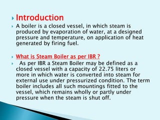
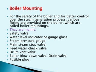
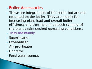
 Introduction
 A boiler is a closed vessel, in which steam is
produced by evaporation of water, at a designed
pressure and temperature, on application of heat
generated by firing fuel.
 What is Steam Boiler as per IBR ?
 As per IBR a Steam Boiler may be defined as a
closed vessel with a capacity of 22.75 liters or
more in which water is converted into steam for
external use under pressurized condition. The term
boiler includes all such mountings fitted to the
vessel, which remains wholly or partly under
pressure when the steam is shut off.
 Fire Tube Boiler
 Hot gases from combustion flow inside the
tubes.
 Tubes submerged in water.
 Used where steam pressure is normally low.
 Compact boiler and can be easily manufactured
in a factory and assembled as a packaged boiler.
 Small industrial Boiler.
 Low initial investment.
 High efficiency ( 80 % )
 Meats wide and sudden load fluctuations.
 Water Tube Boiler
 Water flow through tubes.
 Tubes surrounded by hot combustion gases.
 Power plant boiler.
 High capacity boiler.
 Used for high pressure steam.
 Boiler Mounting
 For the safety of the boiler and for better control
over the steam generation process, various
fitting are provided on the boiler, which are
called boiler mountings.
 They are mainly,
 Safety valve
 Water level indicator or gauge glass
 Steam pressure gauge
 Main steam stop valve
 Feed water check valve
 Drum vent valve
 Boiler blow down valve, Drain valve
 Fusible plug
 Boiler Accessories
 These are integral part of the boiler but are not
mounted on the boiler. They are mainly for
increasing plant load and overall boiler
efficiency and they help in smooth running of
the plant under desired operating conditions.
 They are mainly
 Superheater
 Economiser
 Air pre-heater
 Dearator
 Feed water pumps
 CONSTRUCTION FEATURES
 The THERMAX BOILER is a COMBIMAX boiler
with twin drum, three pass, smoke tube design. The
efficiency of boiler is 92% with economizer.
 The boiler consists of two drums. The
lower drum is the heat exchanger and is called
generator drum. Upper drum is a steam drum,
connected to the generator drums and supported by
risers and down comers. This drum contains a coil
immersed in boiling water that is used to preheat
water going to the economizer. Chevron separator
fitted in the top drum to ensure a minimum dryness
fraction of 99.5%. Mountings on this drum include
gauge glass assemblies, level transmitter, stop, drain
and safety valves etc.
 The feed water pump supplies water to the coil
inside the steam drum. After being preheated
this water enters the economizer and then the
generator drum.
 The burner is fitted on the furnace front
plate. The flue gases from the furnace (radiation
zone) reverse to a set of flue tubes that form the
first convection pass. After traversing this pass,
the flue gases enter the second set of flue tubes
forming the second convection pass. From here
the flue gas enters the economizer and then the
chimney.
 The furnace is corrugated which reduce
the thermal stress.
 Three element drum level control system :
 The level of the water present in the
steam drum or boiler drum should be maintained
at a particular level.
 Three element level control system
takes signals from level transmitter on drum,
flow transmitter for steam (feed forward), and
flow transmitter for water (feed back) and
accordingly maintains a steady level in the drum
through the level control valve.
 The above system will be controlled
through a microprocessor based programmable
controller
 Combustion control :
 The basic objective of the control
system is to maintain the steam pressure
constant at varying loads. Which regulate the fuel
input to the boiler depending on the steam flow
rate and measured steam pressure. Based on the
boiler pressure and the steam withdrawal rate
(feed forward), the controller which will maintain
the requisite firing rate, and also the correct
ratio of air & fuel by taking flow signals from air
flow transmitter and oil flow meter. The same
controller will also receive a signal from the on-
line O2 analyzer and keep excess air levels within
control.
 Drum Coil Outlet temperature control system
 The purpose of this control loop is to
regulate the temperature of feed water at the inlet
of Economizer. To adjust the temperature a 3-
way control valve is used
 Fuel Temperature Control
 The boiler is provided with electric cum
steam heated oil pre-heating tank. Electric
heating is provided for start up. Once steam start
generating above above 3 kg/cm2g the Heating
mode is change over to steam heating.
 Temperature controller controls the fuel
temperature
Sr.
No.
Description Instrument Alarm Action
01 Boiler level
High
Level Controller Yes -
02 Boiler level
Low
Mobray Yes -
03 Boiler level
extra Low
Mobray Yes Trip burner
04 Steam
Pressure high
Pressure switch Yes Controlled shut
down of burner
05 Fuel
temperature
low
RTD Yes Trip burner
06 Fuel pressure
low
Pressure Switch Yes Trip burner
07 Combustion
air pressure
low
Pressure switch Yes -
08 Flue gas
temperature
high
RTD Yes Trip burner
09 Flame Failure Photo cell Yes Trip burner
10 Flue gas
damper closed
Damper logic
(PLC)
Yes Trip burner
 ELECTRICAL
The following safeties have been provided to trip
the burner and give audio visual alarm.
 I. FLAME FAILURE
 A continuous watch on flame is kept by flame
sensor any interruption in flame is immediately
detected by flame sensor & burner programmer
disconnects the electrical supply to fuel solenoid
valve causing burner to trip.
 DRUM LEVEL LOW
 The level switch of the level indicating
controller is used for raising an audio visual
alarm when the water level drops below the set
point, tripping the burner.
 BOILER DRUM LEVEL EXTRA LOW
 Float actuated water level controller detects
the extra low water level & disconnect the
electrical interlock in the burner programmer
causing de- ingestion of fuel solenoid valve,
tripping the burner
 FUEL OIL TEMPERATURE LOW
Fuel temperature switch detects the low fuel
temp. & trips the burner.
 STEAM PRESSURE HIGH
High steam pressure is detected by a steam
pressure switch. It puts OFF the burner.
 COMBUSTION AIR PRESSURE LOW
 The pressure switch provided at the
blower outlet detects the low pressure
condition and gives audio visual alarm.
 FUEL OIL PRESSURE LOW
 The pressure switch provided at the fuel
pump outlet detects this condition and trips
the burner
 Steam Safety Valves
 The steam safety valves on the
boiler have been provided as ultimate safety to
relieve excess steam pressure developed in the
event of failure of steam controller to control the
steam pressure. One safety valve is also provided
on economizer to relieve excessive pressure
developed
 Explosion door
 In the event of excess pressure
developed in the combustion chamber the spring
loaded explosion door mounted on the smoke
chamber opens relieving the pressure saving the
door and burner mounted on it.
 Fusible Plug
 In the event of level controller failure water level
goes down. A fusible plug has been provided at the
top most position of the internal reversal chamber.
Once the water level falls below the plug level, the
plug being exposed to steam its temperature goes
up. When the plug temperature reaches about 400-
420 oC the lead alloy holding the plug in the housing
fuses. As soon as the alloy fuses the plug is forced in
to the furnace. By this a small orifice is created on top
of the reversal chamber from which steam rushes into
the furnace quenching the flame. Consequently the
boiler would be tripped by flame failure. This has
been provided as an ultimate safety. To replace and
maintain the fusible plug a hand hole is provided on
the bottom shell right above the plug location.
 Fuel pump relief valves
 Safety relief valves have been provided
in the fuel pumps to safeguard the fuel pumps against
excessive pressure built up. Regulating relief valves also
have been provided in the fuel discharge line of the fuel
pumps to ensure constant fuel oil pressure at burner
inlet.
 Minimum flow recirculation loop
 The pumps provided for feeding water
to the boiler are centrifugal multistage type and are
continuously run. The level in the boiler is maintained by a
control valve. During start up and very low load operations
the flow through the pump will be less than the minimum
flow required for smooth trouble free operation. For that
minimum flow recirculation loop is provided which
consists of an orifice plate, globe valve and a non return
valve. This line is laid back to the deaerator/feed water
tank. The globe valve is provided for finer adjustments.
 Type :Twin drum, 3 pass, smoke tube
 Steam out put : 16 t/hr. F&A 100 oC
 Design pressure : 12 kg/cm2g
 Fuel Consumption : 974 kg/hr with economizer
1018 kg/hr without
economizer
(NCV of fuel 9650 Kcal/kg)
 Steam production : 15.02 kg/kg of fuel with
economizer
 Heating surface : 389 m2
 Water volume at NWL : 28 m3
 Steam space : 3.7 m2
(1) Stack temperature control
- Keep as low as possible
- If >200°C then recover waste heat
(2) Feed water preheating using economizers
- 6 oC rise in feed water temp. by economizer =
1 % improvement in thermal efficiency
(3) Combustion air pre-heating
- If combustion air temperature is raised by
20° = 1% improvement in thermal efficiency
(4) Incomplete combustion minimization
(5) Excess air control
 1% excess air reduction = 0.6% efficiency rise
(6) Avoid radiation and convection heat loss
Repairing insulation can reduce losses.
(7) Automatic blow down control
(8) Use D.M. water to minimize blow down
(9) Install boiler blow down heat recovery system
(10) Reduction of scaling and soot losses
- Every 22oC increase in stack temperature =
1% efficiency loss
- 3 mm of soot = 2.5% fuel increase
(11) Reduction of boiler steam pressure
(12) Controlling boiler loading
(13) Proper boiler scheduling
(14) Boiler replacement
THANKS

BOILER OPERATION PPT.pptx

  • 2.
     Introduction  Aboiler is a closed vessel, in which steam is produced by evaporation of water, at a designed pressure and temperature, on application of heat generated by firing fuel.  What is Steam Boiler as per IBR ?  As per IBR a Steam Boiler may be defined as a closed vessel with a capacity of 22.75 liters or more in which water is converted into steam for external use under pressurized condition. The term boiler includes all such mountings fitted to the vessel, which remains wholly or partly under pressure when the steam is shut off.
  • 3.
     Fire TubeBoiler  Hot gases from combustion flow inside the tubes.  Tubes submerged in water.  Used where steam pressure is normally low.  Compact boiler and can be easily manufactured in a factory and assembled as a packaged boiler.  Small industrial Boiler.  Low initial investment.  High efficiency ( 80 % )  Meats wide and sudden load fluctuations.
  • 4.
     Water TubeBoiler  Water flow through tubes.  Tubes surrounded by hot combustion gases.  Power plant boiler.  High capacity boiler.  Used for high pressure steam.
  • 5.
     Boiler Mounting For the safety of the boiler and for better control over the steam generation process, various fitting are provided on the boiler, which are called boiler mountings.  They are mainly,  Safety valve  Water level indicator or gauge glass  Steam pressure gauge  Main steam stop valve  Feed water check valve  Drum vent valve  Boiler blow down valve, Drain valve  Fusible plug
  • 6.
     Boiler Accessories These are integral part of the boiler but are not mounted on the boiler. They are mainly for increasing plant load and overall boiler efficiency and they help in smooth running of the plant under desired operating conditions.  They are mainly  Superheater  Economiser  Air pre-heater  Dearator  Feed water pumps
  • 7.
     CONSTRUCTION FEATURES The THERMAX BOILER is a COMBIMAX boiler with twin drum, three pass, smoke tube design. The efficiency of boiler is 92% with economizer.  The boiler consists of two drums. The lower drum is the heat exchanger and is called generator drum. Upper drum is a steam drum, connected to the generator drums and supported by risers and down comers. This drum contains a coil immersed in boiling water that is used to preheat water going to the economizer. Chevron separator fitted in the top drum to ensure a minimum dryness fraction of 99.5%. Mountings on this drum include gauge glass assemblies, level transmitter, stop, drain and safety valves etc.
  • 8.
     The feedwater pump supplies water to the coil inside the steam drum. After being preheated this water enters the economizer and then the generator drum.  The burner is fitted on the furnace front plate. The flue gases from the furnace (radiation zone) reverse to a set of flue tubes that form the first convection pass. After traversing this pass, the flue gases enter the second set of flue tubes forming the second convection pass. From here the flue gas enters the economizer and then the chimney.  The furnace is corrugated which reduce the thermal stress.
  • 9.
     Three elementdrum level control system :  The level of the water present in the steam drum or boiler drum should be maintained at a particular level.  Three element level control system takes signals from level transmitter on drum, flow transmitter for steam (feed forward), and flow transmitter for water (feed back) and accordingly maintains a steady level in the drum through the level control valve.  The above system will be controlled through a microprocessor based programmable controller
  • 10.
     Combustion control:  The basic objective of the control system is to maintain the steam pressure constant at varying loads. Which regulate the fuel input to the boiler depending on the steam flow rate and measured steam pressure. Based on the boiler pressure and the steam withdrawal rate (feed forward), the controller which will maintain the requisite firing rate, and also the correct ratio of air & fuel by taking flow signals from air flow transmitter and oil flow meter. The same controller will also receive a signal from the on- line O2 analyzer and keep excess air levels within control.
  • 11.
     Drum CoilOutlet temperature control system  The purpose of this control loop is to regulate the temperature of feed water at the inlet of Economizer. To adjust the temperature a 3- way control valve is used  Fuel Temperature Control  The boiler is provided with electric cum steam heated oil pre-heating tank. Electric heating is provided for start up. Once steam start generating above above 3 kg/cm2g the Heating mode is change over to steam heating.  Temperature controller controls the fuel temperature
  • 12.
    Sr. No. Description Instrument AlarmAction 01 Boiler level High Level Controller Yes - 02 Boiler level Low Mobray Yes - 03 Boiler level extra Low Mobray Yes Trip burner 04 Steam Pressure high Pressure switch Yes Controlled shut down of burner 05 Fuel temperature low RTD Yes Trip burner 06 Fuel pressure low Pressure Switch Yes Trip burner 07 Combustion air pressure low Pressure switch Yes - 08 Flue gas temperature high RTD Yes Trip burner 09 Flame Failure Photo cell Yes Trip burner 10 Flue gas damper closed Damper logic (PLC) Yes Trip burner
  • 13.
     ELECTRICAL The followingsafeties have been provided to trip the burner and give audio visual alarm.  I. FLAME FAILURE  A continuous watch on flame is kept by flame sensor any interruption in flame is immediately detected by flame sensor & burner programmer disconnects the electrical supply to fuel solenoid valve causing burner to trip.
  • 14.
     DRUM LEVELLOW  The level switch of the level indicating controller is used for raising an audio visual alarm when the water level drops below the set point, tripping the burner.  BOILER DRUM LEVEL EXTRA LOW  Float actuated water level controller detects the extra low water level & disconnect the electrical interlock in the burner programmer causing de- ingestion of fuel solenoid valve, tripping the burner
  • 15.
     FUEL OILTEMPERATURE LOW Fuel temperature switch detects the low fuel temp. & trips the burner.  STEAM PRESSURE HIGH High steam pressure is detected by a steam pressure switch. It puts OFF the burner.
  • 16.
     COMBUSTION AIRPRESSURE LOW  The pressure switch provided at the blower outlet detects the low pressure condition and gives audio visual alarm.  FUEL OIL PRESSURE LOW  The pressure switch provided at the fuel pump outlet detects this condition and trips the burner
  • 17.
     Steam SafetyValves  The steam safety valves on the boiler have been provided as ultimate safety to relieve excess steam pressure developed in the event of failure of steam controller to control the steam pressure. One safety valve is also provided on economizer to relieve excessive pressure developed  Explosion door  In the event of excess pressure developed in the combustion chamber the spring loaded explosion door mounted on the smoke chamber opens relieving the pressure saving the door and burner mounted on it.
  • 18.
     Fusible Plug In the event of level controller failure water level goes down. A fusible plug has been provided at the top most position of the internal reversal chamber. Once the water level falls below the plug level, the plug being exposed to steam its temperature goes up. When the plug temperature reaches about 400- 420 oC the lead alloy holding the plug in the housing fuses. As soon as the alloy fuses the plug is forced in to the furnace. By this a small orifice is created on top of the reversal chamber from which steam rushes into the furnace quenching the flame. Consequently the boiler would be tripped by flame failure. This has been provided as an ultimate safety. To replace and maintain the fusible plug a hand hole is provided on the bottom shell right above the plug location.
  • 19.
     Fuel pumprelief valves  Safety relief valves have been provided in the fuel pumps to safeguard the fuel pumps against excessive pressure built up. Regulating relief valves also have been provided in the fuel discharge line of the fuel pumps to ensure constant fuel oil pressure at burner inlet.  Minimum flow recirculation loop  The pumps provided for feeding water to the boiler are centrifugal multistage type and are continuously run. The level in the boiler is maintained by a control valve. During start up and very low load operations the flow through the pump will be less than the minimum flow required for smooth trouble free operation. For that minimum flow recirculation loop is provided which consists of an orifice plate, globe valve and a non return valve. This line is laid back to the deaerator/feed water tank. The globe valve is provided for finer adjustments.
  • 20.
     Type :Twindrum, 3 pass, smoke tube  Steam out put : 16 t/hr. F&A 100 oC  Design pressure : 12 kg/cm2g  Fuel Consumption : 974 kg/hr with economizer 1018 kg/hr without economizer (NCV of fuel 9650 Kcal/kg)  Steam production : 15.02 kg/kg of fuel with economizer  Heating surface : 389 m2  Water volume at NWL : 28 m3  Steam space : 3.7 m2
  • 21.
    (1) Stack temperaturecontrol - Keep as low as possible - If >200°C then recover waste heat (2) Feed water preheating using economizers - 6 oC rise in feed water temp. by economizer = 1 % improvement in thermal efficiency (3) Combustion air pre-heating - If combustion air temperature is raised by 20° = 1% improvement in thermal efficiency (4) Incomplete combustion minimization (5) Excess air control  1% excess air reduction = 0.6% efficiency rise
  • 22.
    (6) Avoid radiationand convection heat loss Repairing insulation can reduce losses. (7) Automatic blow down control (8) Use D.M. water to minimize blow down (9) Install boiler blow down heat recovery system (10) Reduction of scaling and soot losses - Every 22oC increase in stack temperature = 1% efficiency loss - 3 mm of soot = 2.5% fuel increase (11) Reduction of boiler steam pressure (12) Controlling boiler loading (13) Proper boiler scheduling (14) Boiler replacement
  • 23.