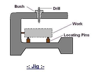
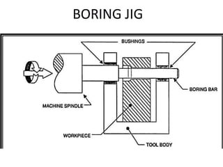
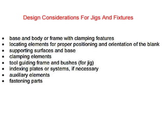
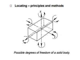
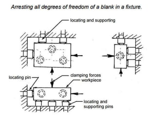
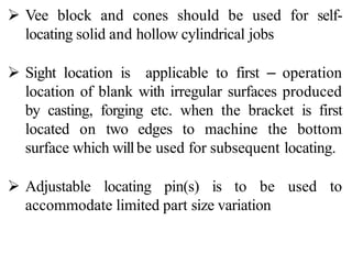
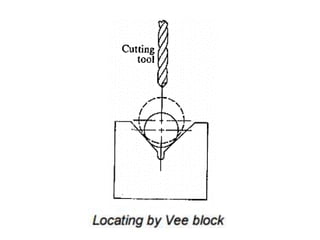
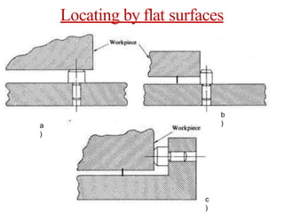
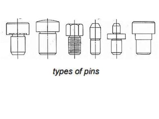
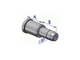
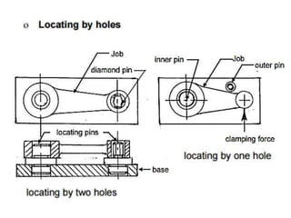
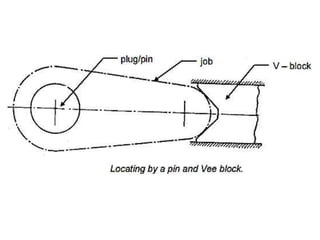
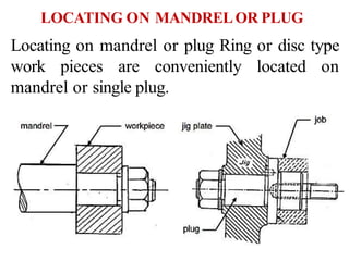
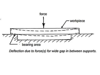
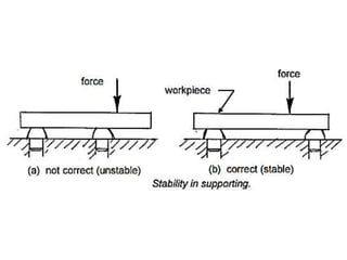
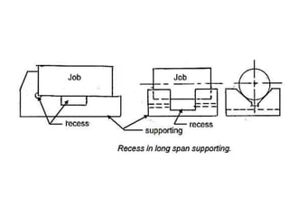
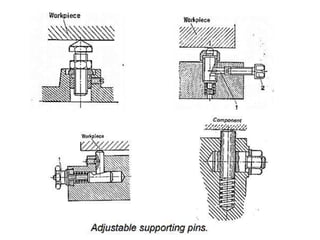
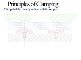
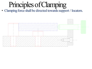
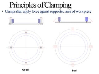
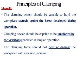
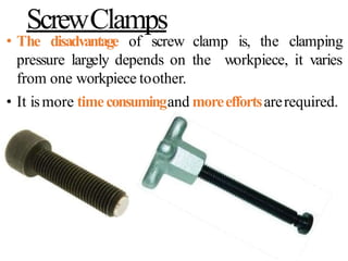
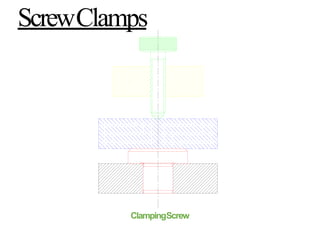
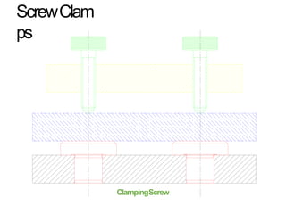
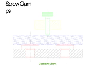
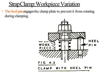
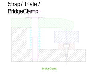
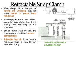
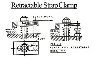
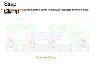
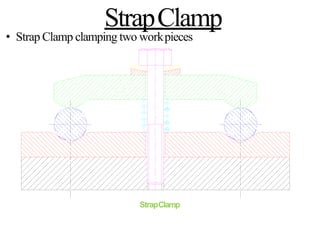
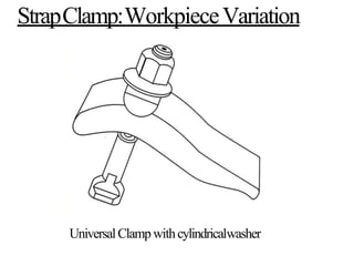
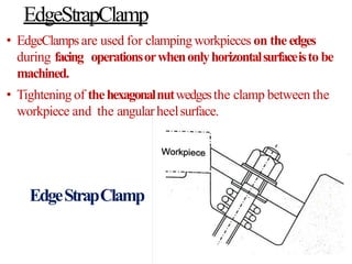
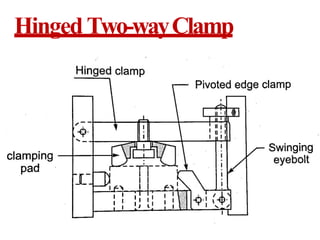
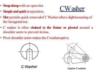
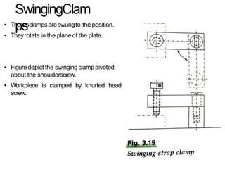
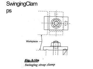
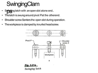
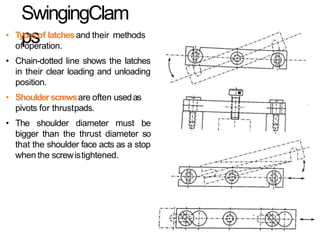
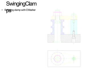
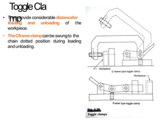
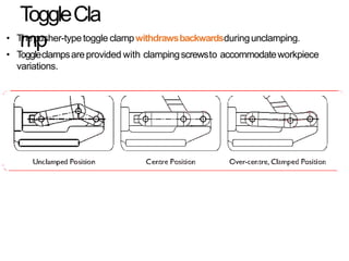
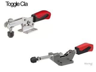
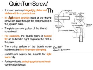
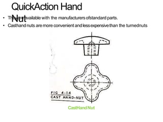
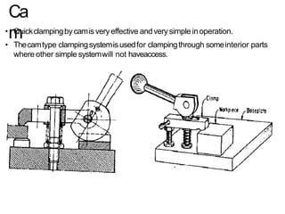
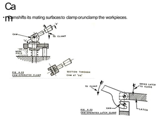
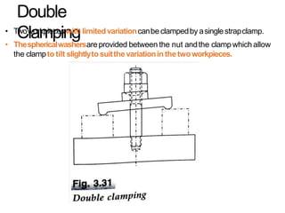
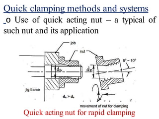
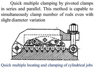
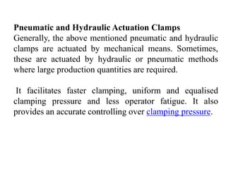
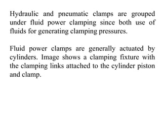
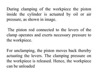
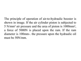
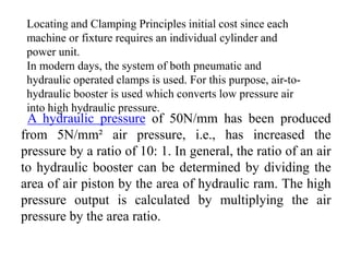
SlideShare a Scribd company logo
1 of 147
LOCATING AND CLAMPING
METHODS
 Jigs and fixtures are the economical ways to
produce a component in mass.
 These are special work holding and tool guiding
device.
 Quality of the performance of a process largely
influenced by the quality of jigs and fixtures used for
this purpose.
 The main purpose of a fixture is to locate and in the
cases hold a workpiece during an operation
A jig differs from a fixture - it guides the
tool to its correct position or towards its correct
movement during an operation in addition to
locating and supporting the workpiece.
An example of jig is when a key is
duplicated, the original key is used as base for
the path reader which guides the movement of
tool to make its duplicate key.
PURPOSE AND ADVANTAGES OF JIGSAND
FIXTURES
1) It reduces or sometimes eliminates the efforts of
marking, measuring and setting of workpiece on a
machine and maintains the accuracy of
performance.
2) The workpiece and tool are relatively located at
their exact positions before the operation
automatically within negligible time. So it reduces
product cycle time.
3) Variability of dimension in mass production is very
low so manufacturing processes supported by use
of jigsand fixtures maintain a consistent quality.
PURPOSE AND ADVANTAGES OF JIGSAND
FIXTURES
(4)Due to low variability in dimension assembly
operation becomes easy, low rejection due to les
defective production is observed.
(5)It reduces the production cycle time so increases
production capacity. Simultaneously working by more
than one tool on the same workpiece is possible.
(6)The operating conditions like speed, feed rate and
depth of cut can be set to higher values due to rigidity
of clamping of workpiece by jigsand fixtures.
PURPOSE AND ADVANTAGES OF JIGSAND
FIXTURES
(7)Operators working becomes comfortable as his
efforts in setting the workpiece can be eliminated.
(8)Semi-skilled operators can be assigned the work so
it saves the cost of manpower also.
(9)There is no need to examine the quality of product
provided that quality of employed jigs and fixtures is
ensured.
IMPORTANT CONSIDERATIONS WHILE
DESIGNING JIGS AND FIXTURES
(a) Study of workpiece and finished component size and
geometry.
(b) Type and capacity of the machine, its extent of automation.
(c) Provision of locating devices in the machine.
(d) Available clamping arrangements in the machine.
(e) Available indexing devices, their accuracy.
(f) Evaluation of variability in the performance results of the
machine.
(g) Rigidity and of the machine tool under consideration.
(h) Study of ejecting devices, safety devices, etc.
(i) Required level of the accuracy in the work and quality to
be produced.
Location refers to the establishment of
a desired relationship between the
workpiece and the jigs or fixture correctness
of location directly influences the accuracy
of the finished product.
LOCATION???...
The jigs and fixtures are desired so that all
undesirable movements of the workpiece can be
restricted.
Determination of the locating points and
clamping of the workpiece serve to restrict
movements of the component in any direction,
while setting it in a particular pre-decided
position relative to the jig.
Before deciding the locating points it is
advisable to find out the all possible
degrees of freedom of the workpiece.
Then some of the degrees of freedom or
all of them are restrained by making
suitable arrangements. These arrangements
are called locators.
LOCATING METHODS
JIGS & FIXTURES
It is a work holding device that holds,
supports and locates the workpiece and
guides the cutting tool for a specific
operation.
JIGS
FIXTURES
It is a work holding device that holds,
supports and locates the workpiece for a
specific operation but does not guide the
cutting tool.
FACTORS CONSIDERED FOR DESIGN, FABRICATION AND
ASSEMBLY OF JIGS AND FIXTURES
Degree of Freedom
Degree of Freedom is defined as
number of independent motion a body
has
3-2-1 Principle of Clamping Workpiece
It is principle of clamping widely used.
1) 3 Pin are used at Bottom
It willrestrict 4 Rotational motion (X,YAxis) and 1 Translation
motion (-Z Direction)
2) 2 Pin
It willRestrict 2 Rotational Motion (Z Axis) and 1 Translation
motion in (+X Direction)
3) 1 Pin
It willrestrict 1 Translation Motion (+Y)
And Pin 3-2-1 combined willrestrict 9 Motion
And Remaining 3 Motion is used to set work-piece at desired
location and can be restricted by Clamp.
(*Notation given i.e +X, -X . Changes according to views)
Some basic principles or rules need to be followed
while planning for locating blanks in fixtures, such as
 One or more surfaces (preferably machined) and / or
drilled / bored hole(s) are to be taken for reference
 The reference surfaces should be significant and
important feature(s) based on which most of the
dimensions are laid down
 Locating should be easy, quick and accurate
 In case of locating by pin, the pins and their mounting
and contact points should be strong, rigid and hard
 A minimum of three point must be used to locate a
horizontal flat surface
 The locating pins should be as far apart as feasible
 Vee block and cones should be used for self-
locating solid and hollow cylindrical jobs
 Sight location is applicable to first – operation
location of blank with irregular surfaces produced
by casting, forging etc. when the bracket is first
located on two edges to machine the bottom
surface which willbe used for subsequent locating.
 Adjustable locating pin(s) is to be used to
accommodate limited part size variation
For locating large jobs by rough bottom
surface one of the three pins may be
replaced by a pivoted arm.
The pivoted arm provides
points.
two contact
General methods of locating
Locating blanks for machining in lathes
In lathes, where the job rotates, the blanks are located
by
 fitting into self centering chuck
 fitting into 4 – independent jaw chuck and dead
centre
 in self –centering collets
 in between live and dead centres
 by using mandrel fitted into the head stock – spindle
 fitting in a separate fixture which is properly clamped
on a driving plate which is coaxially fitted into the
lathe spindle.
Locating for machining in other than lathes
 In machine tools like drilling machine, boring
machine, milling machine, planing machine,
broaching machine and surface grinding machine
the job remains fixed on the bed or work table of
those machine tools.
Fixtures are mostly used in the aforesaid machine
tools and jig specially for drilling, reaming etc. for
batch production.
Locating by flat surfaces
a
)
b
)
c
)
In several cases, workpieces are located by
premachined (drilled, bored or pierced) holes, such as;
∗Locating by two holes where one of the pins has to
be diamond shaped to accommodate tolerance on the
distance between the holes and their diameters
∗Locating by one hole and an external pin which
presents rotation of the blank around the inner pin
∗Locating by one hole and one Vee-block
Locating on mandrel or plug Ring or disc type
work pieces are conveniently located on
mandrel or single plug.
LOCATING ON MANDRELOR PLUG
Supporting –principles and methods
Workpiece has to be properly placed in
the jig or fixture not only for desired positioning
and orientation but also on strong and rigid
support such that the blank does not elastically
deflect or deform under the actions of the
clamping forces, cutting forces and even its own
weigh
Basic principles or rules to be followed while
designing or planning for supporting
should be provided at least at three
 supporting
points
 supporting elements and system have to be enough
strong and rigid to prevent deformation due to
clamping and cutting forces
span should not be large to cause
 unsupported
sagging
 supporting should keep the blank in stable condition
under the forces
 for supporting large flat area proper recess is to be
provided, for better and stable support.
 round or cylindrical workpieces should be supported
(along with locating) on strong vee block of suitable
size
 heavy workpieces with pre-machined bottom surface
should be supported on wide flat areas, otherwise on
flat ended strong pins or plugs.
 if more than three pins are required for supporting
large workpieces then the additional supporting pins
are to be spring loaded or adjustable
additional adjustable supporting pins need to be
provided
∗to compensate part size variation
∗when the supporting surface is large and irregular
∗when clamping and cutting forces are large
• ring or disc type jobs, specially requiring indexing
should be supported (and located) in mandrel
What is Clamping?
Once workpiece is located, it is necessary to
press it against locating surfaces and hold it there
against the force acting upon it.
The tool designer refers to this action as
clamping and the mechanisms used for this
action are known as clamps.
Clamping Principles
•Clamp should firmly hold the workpiece
without distorting it.
•Should overcome the maximum possible force
exerted on workpiece by using minimum
clamping force
• Easy to operate
•Vibrations should tighten the cams and wedges
in the clamp design(if any) and not loosen them
Types Of Clamping
• Mechanical Actuation Clamps
• Pneumatic and Hydraulic Clamps
• Vacuum Clamping
• Magnetic Clamping
• Electrostatic Clamping
• Non Mechanical Clamping
• Special Clamping Operations
Clamping of workpiece in fixtures
In jigs and fixtures the workpiece
or blank has to be strongly and rigidly
clamped against the supporting
surfaces and also the locating features
so that the blank does not get
displaced at all under the cutting forces
during machining.
While designing for clamping the
following factors essentially need to be
considered :
 Clamping need to be strong and rigid enough
to hold the blank firmly during machining
 Clamping should be easy, quick and
consistently adequate
 Clamping should be such that it is not affected
by vibration, chatter or heavy pressure
 Way of clamping and unclamping should not
hinder loading and unloading the blank in the
 the clamp and clamping force must not damage or
deform the workpiece
 clamping operation should be very simple and
quick acting when the jig or fixture is to be used
more frequently and for large volume of work ο
clamps, which move by slide or slip or tend to do
so during applying clamping forces, should be
avoided
 clamping system should comprise of less number
of parts for ease of design, operation and
maintenance
 the wearing parts should be hard or hardened and
also be easily replaceable
 clamping force should act on heavy part(s) and
against supporting and locating surfaces
 clamping force should be away from the
machining thrust forces
 clamping method should be fool proof and safe
 clamping must be reliable but also inexpensive
Various methods of clamping
Clamping method and system are basically of
two categories :
(a) general type without much consideration on
speed of clamping operations
(b) (b) quick acting type
PrinciplesofClamping
•Position
•Strength
•Productivity
•Operatorfatigue
PrinciplesofClamping
Position:
• Clamping systemshould be positioned atthicksections
of the workpiece.
• Clamping should be positioned to directtheclamping
forceon astrong,supportedpartof theworkpiece.
• Clampingon unsupported part bends
slender workpieces, affects accuracy of operation.
Distortionof
unsupported
workpiece
• Clamping systemshould not obstruct loadingand
unloadingof theworkpiece.
• Clamping systemshould not obstruct the pathsofcutting
tool.
• Operator should be able to operate clampseasilyand
safely
• A vertical hole drilled in the bent workpiece would
become angular when the unclamped workpiece springs
back to its originalshape.
• Clampingforce shallbe directed towards support / locators.
PrinciplesofClamping
• Clamp shall be directly in line withthesupport
PrinciplesofClamping
• Clampingforce shallbe directed towards support / locators.
PrinciplesofClamping
• Clampsshallapply force againstsupported area of workpiece
PrinciplesofClamping
Good Bad
PrinciplesofClamping
Strength:
• The clamping system should be capable to hold the
workpiece securely against the forces developed during
operation.
• Clamping device should be capable to be unaffected by
the vibrationsgenerated during anoperation.
• The clamping force should not dent or damage the
workpiece with excessivepressure.
• For clamping weakandfragileworkpiece,clampingforce
should beequally distributed over a wider area of the
workpiece.
• While clamping soft workpiece, clamps should be fitted
with pads or softer materials such as Nylon or Fibre to
prevent damage and denting of the workpiece.
• Clamping faces should be hardened by proper treatments
to minimize their wearingout.
PrinciplesofClamping
Productivity:
• Clamping time should be
minimised by using hand
knobs, tommy bars, knurled
screws, handwheels and
handles, so that clamp can
be tightened or loosened
manually without using
spanners.
• Most of the clamps use
hexagonalnut or hand nut
Hand operated
clampingdevices
PrinciplesofClamping
Handoperated
clampingdevices
PrinciplesofClamping
OperatorFatigue:
• Operator fatigueshould be taken intoaccount.
• Clamping should be operatorfriendly.
• Clampingandreleasingshould be easyand lesstime consuming.
• Maintenanceshould beeasy.
• If considerable number of clamps are to be tightened or
loosened repeatedly, it is better to use pneumatic or hydraulic
clampingwhich reducesoperatorfatigueandsavesclampingtime.
• Handnutsare more convenient for the operator than hexagonal
nutsbecausea spanner isnot required to tightenthem.
Methods ofClamping
Clamping method and system are basically of two
categories:
1.Generaltypewithoutmuchconsiderationof the
speedof clampingoperations.
2.Quick acting clamping method / quick action
clamps.
TypesofClamps
• Screwclamps
• Strapclamps
• Pivotedclamps
• Hingedclamps
• Swingingclamps
• Quick actionclamps
• Powerclamps
• Non-conventionalclamps
ScrewClamps
• Theyare threadeddeviceswith knurledcollar,handknob,
Allenkeys,tommybar orspannerflatsfor rotating and
tightening thescrew.
• Theyare used for lightclamping.
ScrewClamp
ScrewClamps
• The clamping area of screw is
providing apad.
increased by
• The clamping pad remains stationary on the
and rubs on
workpiece while the screwrotates
the conical seat of thepad.
ScrewClamps
• The disadvantage of screw clamp is, the clamping
pressure largely depends on the workpiece, it varies
from one workpiece toother.
• It ismore timeconsumingand moreeffortsarerequired.
ScrewClamps
ClampingScrew
ScrewClam
ps
ClampingScrew
ScrewClam
ps
ClampingScrew
ScrewClam
ps
Strap orPlate Clamps
Strap/ Plate/ BridgeClamps
• It is verysimpleandreliableclampingdevice.
• The clampingforce isapplied byspringloadednut.
StrapClamp
Strap/ Plate/ BridgeClamps
• Theseare made of rectangularplatesand act likelevers.
• The clamps are tightened by rotating a hexagonal nut on a
clampingscrew.
• One end of the clamp presses against the workpiece and the
other end on the heel pin.
• The toe i.e. clamping face of the clamp is curvedand the pressure
face of the heel pin is made sphericalto take care of anyvariations
intheworkpiece.
• Spherical washers permits the clamp to tilt with respect to the
screwand thenut.
Strap/ Plate/ BridgeClamps
• Strap clamps are provided with a washer and
spring belowtheclamp.
• The spring lifts the clamp as the nut is loosened and
workpiece becomesfree.
• The Springholds the clamp inaraisedpositionduring
loading and unloading of the workpiece.
• Washerprevents the entry of the spring in the hole of
the clamp.
• Clamp isrotatedaboutthe studto release theworkpiece.
StrapClamp:WorkpieceVariation
• The clamp is prevented from rotating during clamping by
providing pinatthe heel-end.
• The clamp stud isusuallyatleast10mmindiameterand nearerto
the toe-end than heel-end of theclamp.
StrapClamp:WorkpieceVariation
• Theheelpinengagesthe clamp plate to prevent it from rotating
during clamping.
Strap/ Plate /
BridgeClamp
BridgeClamp
RetractableStrapClamp
• When clamps fall in
loading and unloading,
the path of
they are
made slotted to permit linear
withdrawal.
• Theclampisretracedto the position
shown by chain dotted line during
loading and unloading of the
workpiece.
• Slotted clamp plate so that the
workpiece can be released without
clamprotation.
• Adjustable heel pin is used where
workpiece height is likely to vary
moreconsiderably.
SlottedStrapClampwith
adjustable heelpin
RetractableStrapClamp
“U”Clamp
• U Clampcanberemovedaltogetherto facilitate loading
and unloadingof the workpiece.
UClampwithopen slot
TwoPointClamp
• It isused to clamp twoworkpiecesorto clampasingle
workpieceattwo locations.
SwingingStrapClamp
• Thistype of clampcanberotatedby90oto clearthe passagefor loading and
unloading theworkpiece.
• Theclampis swungto the position shownby the chaindotted line during loading
and unloading oftheworkpieces.
SwingingStrapClamp
SpecialStrap
Clamp
• Theclampshapecanbe changedto suitthe workpieceandtheoperation.
SpiderClamporThree-point Clamp
• Circularandsymmetricalworkpiecescanbe clampedwell with a spider clamp
havingthree clampingpoints, no heel pin isnecessary.
• GooseneckClampcanreducethe clampheight with respectto the work piece
height.
Strap
Clamp
GooseneckClamp
• Strap Clamp clamping two workpieces
StrapClamp
StrapClamp
StrapClamp:WorkpieceVariation
UniversalClampwithcylindricalwasher
EdgeClamps
EdgeStrapClamp
• EdgeClampsare used for clampingworkpieces on the edges
during facing operationsorwhenonlyhorizontalsurfaceisto be
machined.
• Tightening of thehexagonalnutwedgesthe clamp between the
workpiece and the angularheelsurface.
EdgeStrapClamp
EdgeJawClamp
• Edgejawclamp slidesdown the inclinedheelasthe
hexagonal nut istightened.
• Tightening of the hexagonalnut pushes the jawagainst
the workpiece to clampits edge.
EdgeJawClamp
PivotedClamps
PivotedStrapClamp
• Clamps are often pivotedatthe centreto simplify their
operation.
• Knurledheadedscrewisused to loosen and tighten the
clamp.
Pivoted
StrapClamp
PivotedEdgeClamp
• Pivotpinisnearer to theclampingpoint.
• Screwisshifted to the end opposite theclampingpoint.
• Clamping screwbecomes more accessibleto theoperator.
PivotedEdge
Clamps
PivotedTwo-wayClamp
• Pivot action can be used for two-wayclamping of the
workpiece.
• Tightening of the screw makes the curved surface of the
clamp touch the workpiece and further tightening of
the screw clamps the workpiece vertically and
horizontally.
• Two-wayclamp also pushes the workpiece againsttwo
locators.
PivotedTwo-wayClamp
Hinged / LatchClamps
HingedClamp
• Hinged clamp provides rapid clearance of the passagefor
loading andunloading.
• It is clamped with swingingeyebolt. The clamp has open
slot through which the eyebolt can be swung into
position.
• Tightening of the hexagonalnutclamps theworkpiece.
• For loading and unloading the workpiece, the hexagonal
nut is loosened half-a-turn and the eyebolt is swung out
of the open slot to free the hingedplate.
HingedClamp
Hinged Two-wayClamp
• Workpiece is pushed against the location pins by the
pivoted edge clamp which also houses the swinging
eyebolt.
• Knurled nut is used to clamp the workpiece against the
locationpins.
• Workpiece is clamped in two direction by the edge
clampandthe padin the hinge.
• For loading and unloading the workpiece, the knurled
nut is loosened half-a-turn and the eyebolt is swung out
of the open slot to free thehingedplate.
Hinged Two-wayClamp
CWasher
CWasher
• Strapclampwith an openslot.
• Simpleandquickinoperation.
• Slot permits quick removalof CWasher aftera slightloosening of
the hexagonalnut.
• C washer is often chained to the fixture or pivoted around a
shoulder screwto prevent itsloss.
• Pivot shoulder screwmakes the Cwashercaptive.
SwingingClam
ps
SwingingClam
ps
• Thesesclampsareswungto the position.
• Theyrotate in the planeof the plate.
• Figuredepict the swingingclamppivoted
about the shoulderscrew.
• Workpiece is clamped by knurled head
screw.
SwingingClam
ps
SwingingClam
ps
• Swinginglatch with anopenslot atone end..
• Thelatch isswungaround pivot Pat the otherend.
• ShoulderscrewSentersthe open slot duringoperation.
• Theworkpieceisclampedby knurled headscrew.
SwingingClam
ps
• Typesof latchesand their methods
of operation.
• Chain-dotted line shows the latches
in their clear loading and unloading
position.
• Shoulderscrewsare often usedas
pivots for thrustpads.
• The shoulder diameter must be
bigger than the thrust diameter so
that the shoulder face acts as a stop
when the screwistightened.
SwingingClam
ps
• Swinging clamp withCWasher
QuickAction
Clamps
ToggleCla
mp
• Theyprovide considerabledistancefor
loading and unloading of the
workpiece.
• TheCframeclampcanbe swungto the
chain dotted position during loading
andunloading.
ToggleCla
mp
• Thepusher-typetoggle clampwithdrawsbackwardsduringunclamping.
• Toggleclampsareprovided with clampingscrewsto accommodateworkpiece
variations.
ToggleCla
mp
QuickTurnScrew/
ThumbScre
w
• It is used to clamp hingedjig platesand
latcheswithinaquarterturn.
• In unclamped position head of the thumb
screw can pass through the slot provided in
the jig/latchplate.
• The plate can swung clear of the thumb
screwhead.
• For clamping, the thumb screw is turned
90o so its head is right angles to the slot in
the plate.
• The mating surface of the thumb screw
headmust be filedforproperclamping.
• Quarter-turn screws are suitable for light
loadsonly.
• Forheavyloads,swingingeyeboltandknob
combination isused.
QuickAction Hand
Nut
CastHandNut
• Theyareavailable with the manufacturersofstandard parts.
• Casthandnuts aremore convenient andlessexpensivethan the turnednuts
Ca
m
• Quickclampingby camis veryeffective andverysimple inoperation.
• Thecamtype clampingsystemisusedfor clampingthrough someinterior parts
where other simple systemwill not haveaccess.
Ca
m
• Camshifts its mating surfacesto clamporunclamp the workpieces.
Multiple
Clamping
Double
Clamping
• Twoworkpieceswith limitedvariationcanbe clampedby asinglestrapclamp.
• Thesphericalwashersareprovided between the nut andthe clampwhich allow
the clampto tilt slightlytosuitthevariationinthetwoworkpieces.
General clamping methods of common use :
• Screw operated strap clamps
The clamping end of the strap is pressed against
a spring which enables quick unclamping
Common strap type clamping
Clamping from side for unobstructed through
machining (like milling, planing and broaching)
of the top surface.
Clamping from side for free machining of the top surface
Clamping by swing plates
Such clamping, are simple and relatively quick in
operation but is suitable for jobs of relatively
smaller size, simpler shape and requiring lesser
clamping forces.
Clamping by swing plates
Other conventional clamping methods
include :
∗Vices like drilling and milling vices
∗Magnetic chucks
∗Chucks and collets for lathe work
Quick clamping methods and systems
ο Use of quick acting nut – a typical of
such nut and its application
Quick acting nut for rapid clamping
Cam clamping
Quick clamping by cam is very effective and very
simple in operation. Some popular methods and
systems of clamping by cam.
The cam and screw type clamping system is used
for clamping through some interior parts where other
simple system willnot have access.
clamping by cam
Quick multiple clamping by pivoted clamps
in series and parallel. This method is capable to
simultaneously clamp number of rods even with
slight diameter variation
Quick multiple locating and clamping of cylindrical jobs
Pneumatic and Hydraulic Actuation Clamps
Generally, the above mentioned pneumatic and hydraulic
clamps are actuated by mechanical means. Sometimes,
these are actuated by hydraulic or pneumatic methods
where large production quantities are required.
It facilitates faster clamping, uniform and equalised
clamping pressure and less operator fatigue. It also
provides an accurate controlling over clamping pressure.
Hydraulic and pneumatic clamps are grouped
under fluid power clamping since both use of
fluids for generating clamping pressures.
Fluid power clamps are generally actuated by
cylinders. Image shows a clamping fixture with
the clamping links attached to the cylinder piston
and clamp.
During clamping of the workpiece the piston
inside the cylinder is actuated by oil or air
pressure, as shown in image.
The piston rod connected to the levers of the
clamp operates and exerts necessary pressure to
the workpiece.
For unclamping, the piston moves back thereby
actuating the levers. The clamping pressure on
the workpiece is released. Hence, the workpiece
can be unloaded
Fluid Power Clamp – Pneumatic and Hydraulic
Clamping pressure of all clamps will be equal when there
are number of clamps actuated by a single control
valve. The clamping pressure can be varied by regulating
the pressure of the fluid. Higher pressure can be used for
rough and heavy cuts. The pressure can be considerably
reduced during light finishing cut.
There is a risk of sudden pressure drop when the failure
of power will be. This problem can be eliminated by a
providing a non-return valve in the pressure supply line.
If the power fails, the non-return valve automatically is
closed the passage between the pressure line and the
cylinder.
Pneumatically operated clamps differ from hydraulically
operated clamps in the size of the cylinder. Pneumatically
operated clamps require larger cylinder than hydraulic one
because of less pressure exerted by the air. A small hydraulic
cylinder can exert higher pressure as the hydraulic fluid is
incompressible.
Generally, pneumatically operated cylinders are not used
where heavy clamping forces are required because
extremely large cylinders would be required. But
pneumatically operated clamps are convenient because most
of the manufacturing Industries have a hi supply of
compressed air. In a pneumatic clamping, compressed air is
used as the fluid for actuating piston and links. The air is
pressurised about 5 to 6 kg/cm². Generally, a large
compressor is used to supply air to the entire machine shop.
Air to Hydraulic Booster
In a hydraulic clamping, hydraulic oils are used as
the fluid for actuating piston and links. Hydraulic
oils are almost incompressible.
Therefore, it will not cause much speed variations
in hydraulic systems during the variation in load.
The operating pressure of hydraulic system ranges
from 0.7 to 25N/mm². Small compact cylinders are
sufficient for developing nigh clamping force.
However, hydraulic cylinders are slow in operation
in comparison with pneumatic actuators. Oil is
recirculated in the system through a reservoir. The
hydraulic operation of a mechanism requires higher
The principle of operation of air-to-hydraulic booster is
shown in image. If the air cylinder piston is subjected to
5 N/mm² air pressure and the area of piston is 1000mm²,
a force of 5000N is placed upon the ram. If the ram
diameter is 100mm-. the pressure upon the hydraulic oil
must be 50N/mm.
Locating and Clamping Principles initial cost since each
machine or fixture requires an individual cylinder and
power unit.
In modern days, the system of both pneumatic and
hydraulic operated clamps is used. For this purpose, air-to-
hydraulic booster is used which converts low pressure air
into high hydraulic pressure.
A hydraulic pressure of 50N/mm has been produced
from 5N/mm² air pressure, i.e., has increased the
pressure by a ratio of 10: 1. In general, the ratio of an air
to hydraulic booster can be determined by dividing the
area of air piston by the area of hydraulic ram. The high
pressure output is calculated by multiplying the air
pressure by the area ratio.

More Related Content

Similar to Module 4.pptx

DESIGN AND DEVELOPMENT OF MACHINING FIXTURE FOR BD65 FINAL DRIVE CASE ON HORI...
DESIGN AND DEVELOPMENT OF MACHINING FIXTURE FOR BD65 FINAL DRIVE CASE ON HORI...DESIGN AND DEVELOPMENT OF MACHINING FIXTURE FOR BD65 FINAL DRIVE CASE ON HORI...
DESIGN AND DEVELOPMENT OF MACHINING FIXTURE FOR BD65 FINAL DRIVE CASE ON HORI...IAEME Publication
 
jigs & fixtures, gear and thread manufacturing,manufacturing processes,Produ...
 jigs & fixtures, gear and thread manufacturing,manufacturing processes,Produ... jigs & fixtures, gear and thread manufacturing,manufacturing processes,Produ...
jigs & fixtures, gear and thread manufacturing,manufacturing processes,Produ...Prof.Mayur Modi
 
Design and analysis of drill jig
Design and analysis of drill jigDesign and analysis of drill jig
Design and analysis of drill jigKARTIKEY VERMA
 
Uint 1 locating and clamping devices
Uint 1 locating and clamping devicesUint 1 locating and clamping devices
Uint 1 locating and clamping devicesS.DHARANI KUMAR
 
Modular fixtures for inspection in CMM
Modular fixtures for inspection in CMMModular fixtures for inspection in CMM
Modular fixtures for inspection in CMMSuresh Lal
 
Chapt introduction to_jigs_and fixtures
Chapt introduction to_jigs_and fixturesChapt introduction to_jigs_and fixtures
Chapt introduction to_jigs_and fixturesDushyant Vyas
 
Introduction to jigs and fixtures
Introduction to jigs and fixturesIntroduction to jigs and fixtures
Introduction to jigs and fixturesDavor Maričić
 
DESIGN OF FIXTURE OF CONNECTING ROD FOR BORING OPERATION
DESIGN OF FIXTURE OF CONNECTING ROD FOR BORING OPERATIONDESIGN OF FIXTURE OF CONNECTING ROD FOR BORING OPERATION
DESIGN OF FIXTURE OF CONNECTING ROD FOR BORING OPERATIONijsrd.com
 
Jig and Fixtures.pptx.pdf
Jig and Fixtures.pptx.pdfJig and Fixtures.pptx.pdf
Jig and Fixtures.pptx.pdfsawai5
 
Jigs & fixture turning
Jigs & fixture turningJigs & fixture turning
Jigs & fixture turningengdida
 
Jig and fixture
Jig and fixtureJig and fixture
Jig and fixtureNaman Dave
 
Jigs & fixture turning
Jigs & fixture turningJigs & fixture turning
Jigs & fixture turningengdida
 

Similar to Module 4.pptx (20)

Ch 23 jig and fixtures
Ch 23 jig and fixturesCh 23 jig and fixtures
Ch 23 jig and fixtures
 
DESIGN AND DEVELOPMENT OF MACHINING FIXTURE FOR BD65 FINAL DRIVE CASE ON HORI...
DESIGN AND DEVELOPMENT OF MACHINING FIXTURE FOR BD65 FINAL DRIVE CASE ON HORI...DESIGN AND DEVELOPMENT OF MACHINING FIXTURE FOR BD65 FINAL DRIVE CASE ON HORI...
DESIGN AND DEVELOPMENT OF MACHINING FIXTURE FOR BD65 FINAL DRIVE CASE ON HORI...
 
jigs & fixtures, gear and thread manufacturing,manufacturing processes,Produ...
 jigs & fixtures, gear and thread manufacturing,manufacturing processes,Produ... jigs & fixtures, gear and thread manufacturing,manufacturing processes,Produ...
jigs & fixtures, gear and thread manufacturing,manufacturing processes,Produ...
 
UNIT-2-3.pdf
UNIT-2-3.pdfUNIT-2-3.pdf
UNIT-2-3.pdf
 
Design and analysis of drill jig
Design and analysis of drill jigDesign and analysis of drill jig
Design and analysis of drill jig
 
Uint 1 locating and clamping devices
Uint 1 locating and clamping devicesUint 1 locating and clamping devices
Uint 1 locating and clamping devices
 
Jigs fixure
Jigs fixureJigs fixure
Jigs fixure
 
jigs and fixtures_MP
jigs and fixtures_MPjigs and fixtures_MP
jigs and fixtures_MP
 
Modular fixtures for inspection in CMM
Modular fixtures for inspection in CMMModular fixtures for inspection in CMM
Modular fixtures for inspection in CMM
 
Chapt introduction to_jigs_and fixtures
Chapt introduction to_jigs_and fixturesChapt introduction to_jigs_and fixtures
Chapt introduction to_jigs_and fixtures
 
Introduction to jigs and fixtures
Introduction to jigs and fixturesIntroduction to jigs and fixtures
Introduction to jigs and fixtures
 
DESIGN OF FIXTURE OF CONNECTING ROD FOR BORING OPERATION
DESIGN OF FIXTURE OF CONNECTING ROD FOR BORING OPERATIONDESIGN OF FIXTURE OF CONNECTING ROD FOR BORING OPERATION
DESIGN OF FIXTURE OF CONNECTING ROD FOR BORING OPERATION
 
Jig and Fixtures.pptx.pdf
Jig and Fixtures.pptx.pdfJig and Fixtures.pptx.pdf
Jig and Fixtures.pptx.pdf
 
jig & fixture.ppt
jig & fixture.pptjig & fixture.ppt
jig & fixture.ppt
 
Jig project 1
Jig project 1Jig project 1
Jig project 1
 
Jigs & fixture turning
Jigs & fixture turningJigs & fixture turning
Jigs & fixture turning
 
Jig and fixture
Jig and fixtureJig and fixture
Jig and fixture
 
Fixture Designing
Fixture DesigningFixture Designing
Fixture Designing
 
Jigs & fixture turning
Jigs & fixture turningJigs & fixture turning
Jigs & fixture turning
 
Jig and fixtures
Jig and fixturesJig and fixtures
Jig and fixtures
 

Recently uploaded

Abu Dhabi Call Girls O58993O4O2 Call Girls in Abu Dhabi`
Abu Dhabi Call Girls O58993O4O2 Call Girls in Abu Dhabi`Abu Dhabi Call Girls O58993O4O2 Call Girls in Abu Dhabi`
Abu Dhabi Call Girls O58993O4O2 Call Girls in Abu Dhabi`dajasot375
 
Best VIP Call Girls Noida Sector 47 Call Me: 8448380779
Best VIP Call Girls Noida Sector 47 Call Me: 8448380779Best VIP Call Girls Noida Sector 47 Call Me: 8448380779
Best VIP Call Girls Noida Sector 47 Call Me: 8448380779Delhi Call girls
 
A level Digipak development Presentation
A level Digipak development PresentationA level Digipak development Presentation
A level Digipak development Presentationamedia6
 
NO1 Trending kala jadu Love Marriage Black Magic Punjab Powerful Black Magic ...
NO1 Trending kala jadu Love Marriage Black Magic Punjab Powerful Black Magic ...NO1 Trending kala jadu Love Marriage Black Magic Punjab Powerful Black Magic ...
NO1 Trending kala jadu Love Marriage Black Magic Punjab Powerful Black Magic ...Amil baba
 
Best VIP Call Girls Noida Sector 44 Call Me: 8448380779
Best VIP Call Girls Noida Sector 44 Call Me: 8448380779Best VIP Call Girls Noida Sector 44 Call Me: 8448380779
Best VIP Call Girls Noida Sector 44 Call Me: 8448380779Delhi Call girls
 
VIP Call Girls Bhiwandi Ananya 8250192130 Independent Escort Service Bhiwandi
VIP Call Girls Bhiwandi Ananya 8250192130 Independent Escort Service BhiwandiVIP Call Girls Bhiwandi Ananya 8250192130 Independent Escort Service Bhiwandi
VIP Call Girls Bhiwandi Ananya 8250192130 Independent Escort Service BhiwandiSuhani Kapoor
 
VIP Call Girls Service Mehdipatnam Hyderabad Call +91-8250192130
VIP Call Girls Service Mehdipatnam Hyderabad Call +91-8250192130VIP Call Girls Service Mehdipatnam Hyderabad Call +91-8250192130
VIP Call Girls Service Mehdipatnam Hyderabad Call +91-8250192130Suhani Kapoor
 
DragonBall PowerPoint Template for demo.pptx
DragonBall PowerPoint Template for demo.pptxDragonBall PowerPoint Template for demo.pptx
DragonBall PowerPoint Template for demo.pptxmirandajeremy200221
 
Call Girls In Safdarjung Enclave 24/7✡️9711147426✡️ Escorts Service
Call Girls In Safdarjung Enclave 24/7✡️9711147426✡️ Escorts ServiceCall Girls In Safdarjung Enclave 24/7✡️9711147426✡️ Escorts Service
Call Girls In Safdarjung Enclave 24/7✡️9711147426✡️ Escorts Servicejennyeacort
 
VIP Russian Call Girls in Gorakhpur Deepika 8250192130 Independent Escort Ser...
VIP Russian Call Girls in Gorakhpur Deepika 8250192130 Independent Escort Ser...VIP Russian Call Girls in Gorakhpur Deepika 8250192130 Independent Escort Ser...
VIP Russian Call Girls in Gorakhpur Deepika 8250192130 Independent Escort Ser...Suhani Kapoor
 
SD_The MATATAG Curriculum Training Design.pptx
SD_The MATATAG Curriculum Training Design.pptxSD_The MATATAG Curriculum Training Design.pptx
SD_The MATATAG Curriculum Training Design.pptxjanettecruzeiro1
 
VIP College Call Girls Gorakhpur Bhavna 8250192130 Independent Escort Service...
VIP College Call Girls Gorakhpur Bhavna 8250192130 Independent Escort Service...VIP College Call Girls Gorakhpur Bhavna 8250192130 Independent Escort Service...
VIP College Call Girls Gorakhpur Bhavna 8250192130 Independent Escort Service...Suhani Kapoor
 
Raj Nagar Extension Call Girls 9711199012 WhatsApp No, Delhi Escorts in Raj N...
Raj Nagar Extension Call Girls 9711199012 WhatsApp No, Delhi Escorts in Raj N...Raj Nagar Extension Call Girls 9711199012 WhatsApp No, Delhi Escorts in Raj N...
Raj Nagar Extension Call Girls 9711199012 WhatsApp No, Delhi Escorts in Raj N...ankitnayak356677
 
Revit Understanding Reference Planes and Reference lines in Revit for Family ...
Revit Understanding Reference Planes and Reference lines in Revit for Family ...Revit Understanding Reference Planes and Reference lines in Revit for Family ...
Revit Understanding Reference Planes and Reference lines in Revit for Family ...Narsimha murthy
 
Cheap Rate Call girls Kalkaji 9205541914 shot 1500 night
Cheap Rate Call girls Kalkaji 9205541914 shot 1500 nightCheap Rate Call girls Kalkaji 9205541914 shot 1500 night
Cheap Rate Call girls Kalkaji 9205541914 shot 1500 nightDelhi Call girls
 
VIP Call Girls Service Kukatpally Hyderabad Call +91-8250192130
VIP Call Girls Service Kukatpally Hyderabad Call +91-8250192130VIP Call Girls Service Kukatpally Hyderabad Call +91-8250192130
VIP Call Girls Service Kukatpally Hyderabad Call +91-8250192130Suhani Kapoor
 

Recently uploaded (20)

Abu Dhabi Call Girls O58993O4O2 Call Girls in Abu Dhabi`
Abu Dhabi Call Girls O58993O4O2 Call Girls in Abu Dhabi`Abu Dhabi Call Girls O58993O4O2 Call Girls in Abu Dhabi`
Abu Dhabi Call Girls O58993O4O2 Call Girls in Abu Dhabi`
 
Best VIP Call Girls Noida Sector 47 Call Me: 8448380779
Best VIP Call Girls Noida Sector 47 Call Me: 8448380779Best VIP Call Girls Noida Sector 47 Call Me: 8448380779
Best VIP Call Girls Noida Sector 47 Call Me: 8448380779
 
A level Digipak development Presentation
A level Digipak development PresentationA level Digipak development Presentation
A level Digipak development Presentation
 
young call girls in Pandav nagar 🔝 9953056974 🔝 Delhi escort Service
young call girls in Pandav nagar 🔝 9953056974 🔝 Delhi escort Serviceyoung call girls in Pandav nagar 🔝 9953056974 🔝 Delhi escort Service
young call girls in Pandav nagar 🔝 9953056974 🔝 Delhi escort Service
 
escort service sasti (*~Call Girls in Prasad Nagar Metro❤️9953056974
escort service sasti (*~Call Girls in Prasad Nagar Metro❤️9953056974escort service sasti (*~Call Girls in Prasad Nagar Metro❤️9953056974
escort service sasti (*~Call Girls in Prasad Nagar Metro❤️9953056974
 
NO1 Trending kala jadu Love Marriage Black Magic Punjab Powerful Black Magic ...
NO1 Trending kala jadu Love Marriage Black Magic Punjab Powerful Black Magic ...NO1 Trending kala jadu Love Marriage Black Magic Punjab Powerful Black Magic ...
NO1 Trending kala jadu Love Marriage Black Magic Punjab Powerful Black Magic ...
 
Best VIP Call Girls Noida Sector 44 Call Me: 8448380779
Best VIP Call Girls Noida Sector 44 Call Me: 8448380779Best VIP Call Girls Noida Sector 44 Call Me: 8448380779
Best VIP Call Girls Noida Sector 44 Call Me: 8448380779
 
Call Girls Service Mukherjee Nagar @9999965857 Delhi 🫦 No Advance VVIP 🍎 SER...
Call Girls Service Mukherjee Nagar @9999965857 Delhi 🫦 No Advance  VVIP 🍎 SER...Call Girls Service Mukherjee Nagar @9999965857 Delhi 🫦 No Advance  VVIP 🍎 SER...
Call Girls Service Mukherjee Nagar @9999965857 Delhi 🫦 No Advance VVIP 🍎 SER...
 
VIP Call Girls Bhiwandi Ananya 8250192130 Independent Escort Service Bhiwandi
VIP Call Girls Bhiwandi Ananya 8250192130 Independent Escort Service BhiwandiVIP Call Girls Bhiwandi Ananya 8250192130 Independent Escort Service Bhiwandi
VIP Call Girls Bhiwandi Ananya 8250192130 Independent Escort Service Bhiwandi
 
VIP Call Girls Service Mehdipatnam Hyderabad Call +91-8250192130
VIP Call Girls Service Mehdipatnam Hyderabad Call +91-8250192130VIP Call Girls Service Mehdipatnam Hyderabad Call +91-8250192130
VIP Call Girls Service Mehdipatnam Hyderabad Call +91-8250192130
 
DragonBall PowerPoint Template for demo.pptx
DragonBall PowerPoint Template for demo.pptxDragonBall PowerPoint Template for demo.pptx
DragonBall PowerPoint Template for demo.pptx
 
Call Girls In Safdarjung Enclave 24/7✡️9711147426✡️ Escorts Service
Call Girls In Safdarjung Enclave 24/7✡️9711147426✡️ Escorts ServiceCall Girls In Safdarjung Enclave 24/7✡️9711147426✡️ Escorts Service
Call Girls In Safdarjung Enclave 24/7✡️9711147426✡️ Escorts Service
 
VIP Russian Call Girls in Gorakhpur Deepika 8250192130 Independent Escort Ser...
VIP Russian Call Girls in Gorakhpur Deepika 8250192130 Independent Escort Ser...VIP Russian Call Girls in Gorakhpur Deepika 8250192130 Independent Escort Ser...
VIP Russian Call Girls in Gorakhpur Deepika 8250192130 Independent Escort Ser...
 
SD_The MATATAG Curriculum Training Design.pptx
SD_The MATATAG Curriculum Training Design.pptxSD_The MATATAG Curriculum Training Design.pptx
SD_The MATATAG Curriculum Training Design.pptx
 
VIP College Call Girls Gorakhpur Bhavna 8250192130 Independent Escort Service...
VIP College Call Girls Gorakhpur Bhavna 8250192130 Independent Escort Service...VIP College Call Girls Gorakhpur Bhavna 8250192130 Independent Escort Service...
VIP College Call Girls Gorakhpur Bhavna 8250192130 Independent Escort Service...
 
Raj Nagar Extension Call Girls 9711199012 WhatsApp No, Delhi Escorts in Raj N...
Raj Nagar Extension Call Girls 9711199012 WhatsApp No, Delhi Escorts in Raj N...Raj Nagar Extension Call Girls 9711199012 WhatsApp No, Delhi Escorts in Raj N...
Raj Nagar Extension Call Girls 9711199012 WhatsApp No, Delhi Escorts in Raj N...
 
Revit Understanding Reference Planes and Reference lines in Revit for Family ...
Revit Understanding Reference Planes and Reference lines in Revit for Family ...Revit Understanding Reference Planes and Reference lines in Revit for Family ...
Revit Understanding Reference Planes and Reference lines in Revit for Family ...
 
Cheap Rate Call girls Kalkaji 9205541914 shot 1500 night
Cheap Rate Call girls Kalkaji 9205541914 shot 1500 nightCheap Rate Call girls Kalkaji 9205541914 shot 1500 night
Cheap Rate Call girls Kalkaji 9205541914 shot 1500 night
 
young call girls in Vivek Vihar🔝 9953056974 🔝 Delhi escort Service
young call girls in Vivek Vihar🔝 9953056974 🔝 Delhi escort Serviceyoung call girls in Vivek Vihar🔝 9953056974 🔝 Delhi escort Service
young call girls in Vivek Vihar🔝 9953056974 🔝 Delhi escort Service
 
VIP Call Girls Service Kukatpally Hyderabad Call +91-8250192130
VIP Call Girls Service Kukatpally Hyderabad Call +91-8250192130VIP Call Girls Service Kukatpally Hyderabad Call +91-8250192130
VIP Call Girls Service Kukatpally Hyderabad Call +91-8250192130
 

Module 4.pptx

  • 2.  Jigs and fixtures are the economical ways to produce a component in mass.  These are special work holding and tool guiding device.  Quality of the performance of a process largely influenced by the quality of jigs and fixtures used for this purpose.  The main purpose of a fixture is to locate and in the cases hold a workpiece during an operation
  • 3. A jig differs from a fixture - it guides the tool to its correct position or towards its correct movement during an operation in addition to locating and supporting the workpiece. An example of jig is when a key is duplicated, the original key is used as base for the path reader which guides the movement of tool to make its duplicate key.
  • 4. PURPOSE AND ADVANTAGES OF JIGSAND FIXTURES 1) It reduces or sometimes eliminates the efforts of marking, measuring and setting of workpiece on a machine and maintains the accuracy of performance. 2) The workpiece and tool are relatively located at their exact positions before the operation automatically within negligible time. So it reduces product cycle time. 3) Variability of dimension in mass production is very low so manufacturing processes supported by use of jigsand fixtures maintain a consistent quality.
  • 5. PURPOSE AND ADVANTAGES OF JIGSAND FIXTURES (4)Due to low variability in dimension assembly operation becomes easy, low rejection due to les defective production is observed. (5)It reduces the production cycle time so increases production capacity. Simultaneously working by more than one tool on the same workpiece is possible. (6)The operating conditions like speed, feed rate and depth of cut can be set to higher values due to rigidity of clamping of workpiece by jigsand fixtures.
  • 6. PURPOSE AND ADVANTAGES OF JIGSAND FIXTURES (7)Operators working becomes comfortable as his efforts in setting the workpiece can be eliminated. (8)Semi-skilled operators can be assigned the work so it saves the cost of manpower also. (9)There is no need to examine the quality of product provided that quality of employed jigs and fixtures is ensured.
  • 7. IMPORTANT CONSIDERATIONS WHILE DESIGNING JIGS AND FIXTURES (a) Study of workpiece and finished component size and geometry. (b) Type and capacity of the machine, its extent of automation. (c) Provision of locating devices in the machine. (d) Available clamping arrangements in the machine. (e) Available indexing devices, their accuracy. (f) Evaluation of variability in the performance results of the machine. (g) Rigidity and of the machine tool under consideration. (h) Study of ejecting devices, safety devices, etc. (i) Required level of the accuracy in the work and quality to be produced.
  • 8. Location refers to the establishment of a desired relationship between the workpiece and the jigs or fixture correctness of location directly influences the accuracy of the finished product. LOCATION???...
  • 9. The jigs and fixtures are desired so that all undesirable movements of the workpiece can be restricted. Determination of the locating points and clamping of the workpiece serve to restrict movements of the component in any direction, while setting it in a particular pre-decided position relative to the jig.
  • 10. Before deciding the locating points it is advisable to find out the all possible degrees of freedom of the workpiece. Then some of the degrees of freedom or all of them are restrained by making suitable arrangements. These arrangements are called locators.
  • 12. It is a work holding device that holds, supports and locates the workpiece and guides the cutting tool for a specific operation. JIGS
  • 13.
  • 14.
  • 15. FIXTURES It is a work holding device that holds, supports and locates the workpiece for a specific operation but does not guide the cutting tool.
  • 16.
  • 17.
  • 18.
  • 19.
  • 20.
  • 21. FACTORS CONSIDERED FOR DESIGN, FABRICATION AND ASSEMBLY OF JIGS AND FIXTURES
  • 22.
  • 23.
  • 24.
  • 25. Degree of Freedom Degree of Freedom is defined as number of independent motion a body has
  • 26. 3-2-1 Principle of Clamping Workpiece It is principle of clamping widely used. 1) 3 Pin are used at Bottom It willrestrict 4 Rotational motion (X,YAxis) and 1 Translation motion (-Z Direction) 2) 2 Pin It willRestrict 2 Rotational Motion (Z Axis) and 1 Translation motion in (+X Direction) 3) 1 Pin It willrestrict 1 Translation Motion (+Y) And Pin 3-2-1 combined willrestrict 9 Motion And Remaining 3 Motion is used to set work-piece at desired location and can be restricted by Clamp. (*Notation given i.e +X, -X . Changes according to views)
  • 27.
  • 28. Some basic principles or rules need to be followed while planning for locating blanks in fixtures, such as  One or more surfaces (preferably machined) and / or drilled / bored hole(s) are to be taken for reference  The reference surfaces should be significant and important feature(s) based on which most of the dimensions are laid down  Locating should be easy, quick and accurate  In case of locating by pin, the pins and their mounting and contact points should be strong, rigid and hard  A minimum of three point must be used to locate a horizontal flat surface  The locating pins should be as far apart as feasible
  • 29.  Vee block and cones should be used for self- locating solid and hollow cylindrical jobs  Sight location is applicable to first – operation location of blank with irregular surfaces produced by casting, forging etc. when the bracket is first located on two edges to machine the bottom surface which willbe used for subsequent locating.  Adjustable locating pin(s) is to be used to accommodate limited part size variation
  • 30.
  • 31. For locating large jobs by rough bottom surface one of the three pins may be replaced by a pivoted arm. The pivoted arm provides points. two contact
  • 32.
  • 33.
  • 34. General methods of locating Locating blanks for machining in lathes In lathes, where the job rotates, the blanks are located by  fitting into self centering chuck  fitting into 4 – independent jaw chuck and dead centre  in self –centering collets  in between live and dead centres  by using mandrel fitted into the head stock – spindle  fitting in a separate fixture which is properly clamped on a driving plate which is coaxially fitted into the lathe spindle.
  • 35.
  • 36.
  • 37. Locating for machining in other than lathes  In machine tools like drilling machine, boring machine, milling machine, planing machine, broaching machine and surface grinding machine the job remains fixed on the bed or work table of those machine tools. Fixtures are mostly used in the aforesaid machine tools and jig specially for drilling, reaming etc. for batch production.
  • 38. Locating by flat surfaces a ) b ) c )
  • 39.
  • 40.
  • 41. In several cases, workpieces are located by premachined (drilled, bored or pierced) holes, such as; ∗Locating by two holes where one of the pins has to be diamond shaped to accommodate tolerance on the distance between the holes and their diameters ∗Locating by one hole and an external pin which presents rotation of the blank around the inner pin ∗Locating by one hole and one Vee-block
  • 42.
  • 43.
  • 44. Locating on mandrel or plug Ring or disc type work pieces are conveniently located on mandrel or single plug. LOCATING ON MANDRELOR PLUG
  • 45.
  • 46. Supporting –principles and methods Workpiece has to be properly placed in the jig or fixture not only for desired positioning and orientation but also on strong and rigid support such that the blank does not elastically deflect or deform under the actions of the clamping forces, cutting forces and even its own weigh
  • 47. Basic principles or rules to be followed while designing or planning for supporting should be provided at least at three  supporting points  supporting elements and system have to be enough strong and rigid to prevent deformation due to clamping and cutting forces span should not be large to cause  unsupported sagging  supporting should keep the blank in stable condition under the forces
  • 48.  for supporting large flat area proper recess is to be provided, for better and stable support.  round or cylindrical workpieces should be supported (along with locating) on strong vee block of suitable size  heavy workpieces with pre-machined bottom surface should be supported on wide flat areas, otherwise on flat ended strong pins or plugs.  if more than three pins are required for supporting large workpieces then the additional supporting pins are to be spring loaded or adjustable
  • 49. additional adjustable supporting pins need to be provided ∗to compensate part size variation ∗when the supporting surface is large and irregular ∗when clamping and cutting forces are large • ring or disc type jobs, specially requiring indexing should be supported (and located) in mandrel
  • 50.
  • 51.
  • 52.
  • 53.
  • 54. What is Clamping? Once workpiece is located, it is necessary to press it against locating surfaces and hold it there against the force acting upon it. The tool designer refers to this action as clamping and the mechanisms used for this action are known as clamps.
  • 55. Clamping Principles •Clamp should firmly hold the workpiece without distorting it. •Should overcome the maximum possible force exerted on workpiece by using minimum clamping force • Easy to operate •Vibrations should tighten the cams and wedges in the clamp design(if any) and not loosen them
  • 56. Types Of Clamping • Mechanical Actuation Clamps • Pneumatic and Hydraulic Clamps • Vacuum Clamping • Magnetic Clamping • Electrostatic Clamping • Non Mechanical Clamping • Special Clamping Operations
  • 57. Clamping of workpiece in fixtures In jigs and fixtures the workpiece or blank has to be strongly and rigidly clamped against the supporting surfaces and also the locating features so that the blank does not get displaced at all under the cutting forces during machining.
  • 58. While designing for clamping the following factors essentially need to be considered :  Clamping need to be strong and rigid enough to hold the blank firmly during machining  Clamping should be easy, quick and consistently adequate  Clamping should be such that it is not affected by vibration, chatter or heavy pressure  Way of clamping and unclamping should not hinder loading and unloading the blank in the
  • 59.  the clamp and clamping force must not damage or deform the workpiece  clamping operation should be very simple and quick acting when the jig or fixture is to be used more frequently and for large volume of work ο clamps, which move by slide or slip or tend to do so during applying clamping forces, should be avoided  clamping system should comprise of less number of parts for ease of design, operation and maintenance
  • 60.  the wearing parts should be hard or hardened and also be easily replaceable  clamping force should act on heavy part(s) and against supporting and locating surfaces  clamping force should be away from the machining thrust forces  clamping method should be fool proof and safe  clamping must be reliable but also inexpensive
  • 61. Various methods of clamping Clamping method and system are basically of two categories : (a) general type without much consideration on speed of clamping operations (b) (b) quick acting type
  • 63. PrinciplesofClamping Position: • Clamping systemshould be positioned atthicksections of the workpiece. • Clamping should be positioned to directtheclamping forceon astrong,supportedpartof theworkpiece. • Clampingon unsupported part bends slender workpieces, affects accuracy of operation. Distortionof unsupported workpiece
  • 64. • Clamping systemshould not obstruct loadingand unloadingof theworkpiece. • Clamping systemshould not obstruct the pathsofcutting tool. • Operator should be able to operate clampseasilyand safely • A vertical hole drilled in the bent workpiece would become angular when the unclamped workpiece springs back to its originalshape.
  • 65. • Clampingforce shallbe directed towards support / locators. PrinciplesofClamping
  • 66. • Clamp shall be directly in line withthesupport PrinciplesofClamping
  • 67. • Clampingforce shallbe directed towards support / locators. PrinciplesofClamping
  • 68. • Clampsshallapply force againstsupported area of workpiece PrinciplesofClamping Good Bad
  • 69. PrinciplesofClamping Strength: • The clamping system should be capable to hold the workpiece securely against the forces developed during operation. • Clamping device should be capable to be unaffected by the vibrationsgenerated during anoperation. • The clamping force should not dent or damage the workpiece with excessivepressure.
  • 70. • For clamping weakandfragileworkpiece,clampingforce should beequally distributed over a wider area of the workpiece. • While clamping soft workpiece, clamps should be fitted with pads or softer materials such as Nylon or Fibre to prevent damage and denting of the workpiece. • Clamping faces should be hardened by proper treatments to minimize their wearingout.
  • 71. PrinciplesofClamping Productivity: • Clamping time should be minimised by using hand knobs, tommy bars, knurled screws, handwheels and handles, so that clamp can be tightened or loosened manually without using spanners. • Most of the clamps use hexagonalnut or hand nut Hand operated clampingdevices
  • 73. PrinciplesofClamping OperatorFatigue: • Operator fatigueshould be taken intoaccount. • Clamping should be operatorfriendly. • Clampingandreleasingshould be easyand lesstime consuming. • Maintenanceshould beeasy. • If considerable number of clamps are to be tightened or loosened repeatedly, it is better to use pneumatic or hydraulic clampingwhich reducesoperatorfatigueandsavesclampingtime. • Handnutsare more convenient for the operator than hexagonal nutsbecausea spanner isnot required to tightenthem.
  • 74. Methods ofClamping Clamping method and system are basically of two categories: 1.Generaltypewithoutmuchconsiderationof the speedof clampingoperations. 2.Quick acting clamping method / quick action clamps.
  • 75. TypesofClamps • Screwclamps • Strapclamps • Pivotedclamps • Hingedclamps • Swingingclamps • Quick actionclamps • Powerclamps • Non-conventionalclamps
  • 76. ScrewClamps • Theyare threadeddeviceswith knurledcollar,handknob, Allenkeys,tommybar orspannerflatsfor rotating and tightening thescrew. • Theyare used for lightclamping. ScrewClamp
  • 77. ScrewClamps • The clamping area of screw is providing apad. increased by • The clamping pad remains stationary on the and rubs on workpiece while the screwrotates the conical seat of thepad.
  • 78. ScrewClamps • The disadvantage of screw clamp is, the clamping pressure largely depends on the workpiece, it varies from one workpiece toother. • It ismore timeconsumingand moreeffortsarerequired.
  • 84. Strap/ Plate/ BridgeClamps • It is verysimpleandreliableclampingdevice. • The clampingforce isapplied byspringloadednut. StrapClamp
  • 85. Strap/ Plate/ BridgeClamps • Theseare made of rectangularplatesand act likelevers. • The clamps are tightened by rotating a hexagonal nut on a clampingscrew. • One end of the clamp presses against the workpiece and the other end on the heel pin. • The toe i.e. clamping face of the clamp is curvedand the pressure face of the heel pin is made sphericalto take care of anyvariations intheworkpiece. • Spherical washers permits the clamp to tilt with respect to the screwand thenut.
  • 86. Strap/ Plate/ BridgeClamps • Strap clamps are provided with a washer and spring belowtheclamp. • The spring lifts the clamp as the nut is loosened and workpiece becomesfree. • The Springholds the clamp inaraisedpositionduring loading and unloading of the workpiece. • Washerprevents the entry of the spring in the hole of the clamp. • Clamp isrotatedaboutthe studto release theworkpiece.
  • 87. StrapClamp:WorkpieceVariation • The clamp is prevented from rotating during clamping by providing pinatthe heel-end. • The clamp stud isusuallyatleast10mmindiameterand nearerto the toe-end than heel-end of theclamp.
  • 88. StrapClamp:WorkpieceVariation • Theheelpinengagesthe clamp plate to prevent it from rotating during clamping.
  • 90. RetractableStrapClamp • When clamps fall in loading and unloading, the path of they are made slotted to permit linear withdrawal. • Theclampisretracedto the position shown by chain dotted line during loading and unloading of the workpiece. • Slotted clamp plate so that the workpiece can be released without clamprotation. • Adjustable heel pin is used where workpiece height is likely to vary moreconsiderably. SlottedStrapClampwith adjustable heelpin
  • 92. “U”Clamp • U Clampcanberemovedaltogetherto facilitate loading and unloadingof the workpiece. UClampwithopen slot
  • 93. TwoPointClamp • It isused to clamp twoworkpiecesorto clampasingle workpieceattwo locations.
  • 94. SwingingStrapClamp • Thistype of clampcanberotatedby90oto clearthe passagefor loading and unloading theworkpiece. • Theclampis swungto the position shownby the chaindotted line during loading and unloading oftheworkpieces. SwingingStrapClamp
  • 95. SpecialStrap Clamp • Theclampshapecanbe changedto suitthe workpieceandtheoperation. SpiderClamporThree-point Clamp • Circularandsymmetricalworkpiecescanbe clampedwell with a spider clamp havingthree clampingpoints, no heel pin isnecessary.
  • 96. • GooseneckClampcanreducethe clampheight with respectto the work piece height. Strap Clamp GooseneckClamp
  • 97. • Strap Clamp clamping two workpieces StrapClamp StrapClamp
  • 100. EdgeStrapClamp • EdgeClampsare used for clampingworkpieces on the edges during facing operationsorwhenonlyhorizontalsurfaceisto be machined. • Tightening of thehexagonalnutwedgesthe clamp between the workpiece and the angularheelsurface. EdgeStrapClamp
  • 101. EdgeJawClamp • Edgejawclamp slidesdown the inclinedheelasthe hexagonal nut istightened. • Tightening of the hexagonalnut pushes the jawagainst the workpiece to clampits edge. EdgeJawClamp
  • 103. PivotedStrapClamp • Clamps are often pivotedatthe centreto simplify their operation. • Knurledheadedscrewisused to loosen and tighten the clamp. Pivoted StrapClamp
  • 104. PivotedEdgeClamp • Pivotpinisnearer to theclampingpoint. • Screwisshifted to the end opposite theclampingpoint. • Clamping screwbecomes more accessibleto theoperator. PivotedEdge Clamps
  • 105. PivotedTwo-wayClamp • Pivot action can be used for two-wayclamping of the workpiece. • Tightening of the screw makes the curved surface of the clamp touch the workpiece and further tightening of the screw clamps the workpiece vertically and horizontally. • Two-wayclamp also pushes the workpiece againsttwo locators.
  • 109. • Hinged clamp provides rapid clearance of the passagefor loading andunloading. • It is clamped with swingingeyebolt. The clamp has open slot through which the eyebolt can be swung into position. • Tightening of the hexagonalnutclamps theworkpiece. • For loading and unloading the workpiece, the hexagonal nut is loosened half-a-turn and the eyebolt is swung out of the open slot to free the hingedplate. HingedClamp
  • 110. Hinged Two-wayClamp • Workpiece is pushed against the location pins by the pivoted edge clamp which also houses the swinging eyebolt. • Knurled nut is used to clamp the workpiece against the locationpins. • Workpiece is clamped in two direction by the edge clampandthe padin the hinge. • For loading and unloading the workpiece, the knurled nut is loosened half-a-turn and the eyebolt is swung out of the open slot to free thehingedplate.
  • 113. CWasher • Strapclampwith an openslot. • Simpleandquickinoperation. • Slot permits quick removalof CWasher aftera slightloosening of the hexagonalnut. • C washer is often chained to the fixture or pivoted around a shoulder screwto prevent itsloss. • Pivot shoulder screwmakes the Cwashercaptive.
  • 115. SwingingClam ps • Thesesclampsareswungto the position. • Theyrotate in the planeof the plate. • Figuredepict the swingingclamppivoted about the shoulderscrew. • Workpiece is clamped by knurled head screw.
  • 117. SwingingClam ps • Swinginglatch with anopenslot atone end.. • Thelatch isswungaround pivot Pat the otherend. • ShoulderscrewSentersthe open slot duringoperation. • Theworkpieceisclampedby knurled headscrew.
  • 118. SwingingClam ps • Typesof latchesand their methods of operation. • Chain-dotted line shows the latches in their clear loading and unloading position. • Shoulderscrewsare often usedas pivots for thrustpads. • The shoulder diameter must be bigger than the thrust diameter so that the shoulder face acts as a stop when the screwistightened.
  • 121. ToggleCla mp • Theyprovide considerabledistancefor loading and unloading of the workpiece. • TheCframeclampcanbe swungto the chain dotted position during loading andunloading.
  • 122. ToggleCla mp • Thepusher-typetoggle clampwithdrawsbackwardsduringunclamping. • Toggleclampsareprovided with clampingscrewsto accommodateworkpiece variations.
  • 124. QuickTurnScrew/ ThumbScre w • It is used to clamp hingedjig platesand latcheswithinaquarterturn. • In unclamped position head of the thumb screw can pass through the slot provided in the jig/latchplate. • The plate can swung clear of the thumb screwhead. • For clamping, the thumb screw is turned 90o so its head is right angles to the slot in the plate. • The mating surface of the thumb screw headmust be filedforproperclamping. • Quarter-turn screws are suitable for light loadsonly. • Forheavyloads,swingingeyeboltandknob combination isused.
  • 125. QuickAction Hand Nut CastHandNut • Theyareavailable with the manufacturersofstandard parts. • Casthandnuts aremore convenient andlessexpensivethan the turnednuts
  • 126. Ca m • Quickclampingby camis veryeffective andverysimple inoperation. • Thecamtype clampingsystemisusedfor clampingthrough someinterior parts where other simple systemwill not haveaccess.
  • 127. Ca m • Camshifts its mating surfacesto clamporunclamp the workpieces.
  • 129. Double Clamping • Twoworkpieceswith limitedvariationcanbe clampedby asinglestrapclamp. • Thesphericalwashersareprovided between the nut andthe clampwhich allow the clampto tilt slightlytosuitthevariationinthetwoworkpieces.
  • 130. General clamping methods of common use : • Screw operated strap clamps The clamping end of the strap is pressed against a spring which enables quick unclamping Common strap type clamping
  • 131. Clamping from side for unobstructed through machining (like milling, planing and broaching) of the top surface. Clamping from side for free machining of the top surface
  • 132. Clamping by swing plates Such clamping, are simple and relatively quick in operation but is suitable for jobs of relatively smaller size, simpler shape and requiring lesser clamping forces. Clamping by swing plates
  • 133. Other conventional clamping methods include : ∗Vices like drilling and milling vices ∗Magnetic chucks ∗Chucks and collets for lathe work
  • 134. Quick clamping methods and systems ο Use of quick acting nut – a typical of such nut and its application Quick acting nut for rapid clamping
  • 135. Cam clamping Quick clamping by cam is very effective and very simple in operation. Some popular methods and systems of clamping by cam. The cam and screw type clamping system is used for clamping through some interior parts where other simple system willnot have access.
  • 137.
  • 138. Quick multiple clamping by pivoted clamps in series and parallel. This method is capable to simultaneously clamp number of rods even with slight diameter variation Quick multiple locating and clamping of cylindrical jobs
  • 139. Pneumatic and Hydraulic Actuation Clamps Generally, the above mentioned pneumatic and hydraulic clamps are actuated by mechanical means. Sometimes, these are actuated by hydraulic or pneumatic methods where large production quantities are required. It facilitates faster clamping, uniform and equalised clamping pressure and less operator fatigue. It also provides an accurate controlling over clamping pressure.
  • 140. Hydraulic and pneumatic clamps are grouped under fluid power clamping since both use of fluids for generating clamping pressures. Fluid power clamps are generally actuated by cylinders. Image shows a clamping fixture with the clamping links attached to the cylinder piston and clamp.
  • 141. During clamping of the workpiece the piston inside the cylinder is actuated by oil or air pressure, as shown in image. The piston rod connected to the levers of the clamp operates and exerts necessary pressure to the workpiece. For unclamping, the piston moves back thereby actuating the levers. The clamping pressure on the workpiece is released. Hence, the workpiece can be unloaded
  • 142. Fluid Power Clamp – Pneumatic and Hydraulic Clamping pressure of all clamps will be equal when there are number of clamps actuated by a single control valve. The clamping pressure can be varied by regulating the pressure of the fluid. Higher pressure can be used for rough and heavy cuts. The pressure can be considerably reduced during light finishing cut. There is a risk of sudden pressure drop when the failure of power will be. This problem can be eliminated by a providing a non-return valve in the pressure supply line. If the power fails, the non-return valve automatically is closed the passage between the pressure line and the cylinder.
  • 143. Pneumatically operated clamps differ from hydraulically operated clamps in the size of the cylinder. Pneumatically operated clamps require larger cylinder than hydraulic one because of less pressure exerted by the air. A small hydraulic cylinder can exert higher pressure as the hydraulic fluid is incompressible. Generally, pneumatically operated cylinders are not used where heavy clamping forces are required because extremely large cylinders would be required. But pneumatically operated clamps are convenient because most of the manufacturing Industries have a hi supply of compressed air. In a pneumatic clamping, compressed air is used as the fluid for actuating piston and links. The air is pressurised about 5 to 6 kg/cm². Generally, a large compressor is used to supply air to the entire machine shop.
  • 144. Air to Hydraulic Booster In a hydraulic clamping, hydraulic oils are used as the fluid for actuating piston and links. Hydraulic oils are almost incompressible. Therefore, it will not cause much speed variations in hydraulic systems during the variation in load. The operating pressure of hydraulic system ranges from 0.7 to 25N/mm². Small compact cylinders are sufficient for developing nigh clamping force. However, hydraulic cylinders are slow in operation in comparison with pneumatic actuators. Oil is recirculated in the system through a reservoir. The hydraulic operation of a mechanism requires higher
  • 145.
  • 146. The principle of operation of air-to-hydraulic booster is shown in image. If the air cylinder piston is subjected to 5 N/mm² air pressure and the area of piston is 1000mm², a force of 5000N is placed upon the ram. If the ram diameter is 100mm-. the pressure upon the hydraulic oil must be 50N/mm.
  • 147. Locating and Clamping Principles initial cost since each machine or fixture requires an individual cylinder and power unit. In modern days, the system of both pneumatic and hydraulic operated clamps is used. For this purpose, air-to- hydraulic booster is used which converts low pressure air into high hydraulic pressure. A hydraulic pressure of 50N/mm has been produced from 5N/mm² air pressure, i.e., has increased the pressure by a ratio of 10: 1. In general, the ratio of an air to hydraulic booster can be determined by dividing the area of air piston by the area of hydraulic ram. The high pressure output is calculated by multiplying the air pressure by the area ratio.