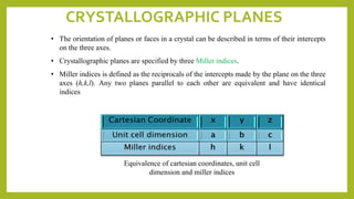
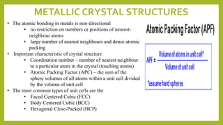
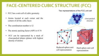
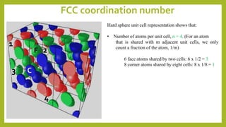
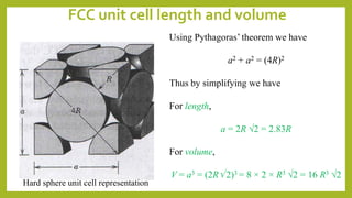
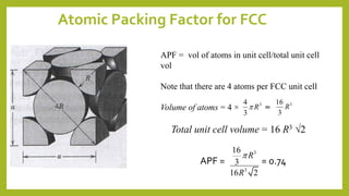
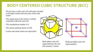
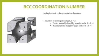
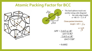
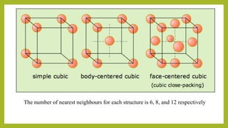
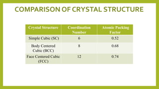
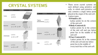
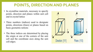
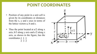
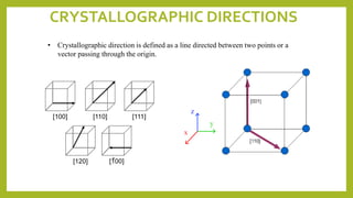
JIF 419
MATERIALS SCIENCE
Webex 1
STRUCTURE OF A
CRYSTAL
FUNDAMENTAL CONCEPTS
• Crystalline material : atoms self-organize in a periodic 3D
pattern – all metals, many ceramic, certain polymers.
• Noncrystalline (amorphous) material : lacks a systematic atomic
arrangement
• Crystal structure
• the manner in which atoms, ions or molecules are spatially
arranged.
• In the simplest crystals, the structural unit is a single
atom. The smallest structural unit may comprise many
atoms or molecules.
• described in terms of a lattice, with a group of atoms
attached identically to every lattice point.
• The group of atoms is called the basis; when repeated
in space it forms the crystal structure.
Crystalline Non-Crystalline
(amorphous)
lattice
UNIT CELLS
• basic structural unit or building block that can describe the crystal structure. Repetition of the unit
cell generates the entire crystal.
• is a parallelepiped and can be packed periodically by integer displacements of the unit cell
parameters. The unit cell parameters are the three coordinate lengths (axial length) (a, b, c)
determined by placing the origin of the coordinate system at a lattice point, and the three angles
(interaxial angles) (,,) subtended by the lattice cell axes.
Thus a unit cell with a=b=c and
===90 is a cube. The various
unit cells are generated from the
different values of a,b,c and ,,.
An analysis of how to fill space
periodically with lattice points shows
that only seven different unit cells are
required to describe all the possible
point lattices, and these are termed
the seven crystal systems.
CRYSTAL SYSTEMS • These seven crystal systems are
each defined using primitive unit
cells, in which each primitive cell
only contains a single lattice point
placed at the origin of the unit cell.
• Lattice types:
Primitive (P)
Lattice points lie on the corners
of the unit cell.
Body-Centered (I)
Lattice points lie at the corners
of the unit cell and one lattice
point lies in the middle of the
unit cell
Face Centered (F)
Lattice points lie at the corners
of the unit cell and one lattice
point lies in the middle of
every/each face of the unit cell.
POINTS, DIRECTION AND PLANES
• In crystalline materials, necessary to specify
points, direction and planes within unit cell
and in crystal lattice
• Three numbers (indices) used to designate
points, directions (lines) or planes based on
basic geometric notions
• The three indices are determined by placing
the origin at one of the corners of the unit
cell and the coordinate axes along the unit
cell edges.
• Position of any point in a unit cell is
given by its coordinates or distances
from the x, y and z axes in terms of
the lattice vectors a, b and c.
• Thus the point located at a/2 along x
axis, b/3 along y axis and c/2 along z
axis, as shown in the figure, has the
coordinates 1 1 1
2 3 2
POINT COORDINATES
CRYSTALLOGRAPHIC DIRECTIONS
• Crystallographic direction is defined as a line directed between two points or a
vector passing through the origin.
1. Always establish an origin
2. Determine coordinates of vector tail, pt. 1: x1,
y1, & z1; and vector head, pt. 2: x2, y2, & z2.
3. Subtract the head point coordinates with tail
point coordinates.
4. Normalize coordinate differences in terms of
lattice parameters a, b, and c:
5. Adjust to smallest integer values
6. Enclose in square brackets with no commas
[uvw]
ex:
pt. 1 x1 = 0, y1 = 0, z1 = 0
=> 1, 0, 1/2
=> [ 201 ]
z
x
y
=> 2, 0, 1
pt. 2
head
pt. 1:
tail
pt. 2 x2 = a, y2 = 0, z2 = c/2
a
b
c
CRYSTALLOGRAPHIC DIRECTIONS
-4, 1, 2
z
x
where the overbar represents a
negative index
[ 412 ]=>
y
Example 2:
pt. 1 x1 = a, y1 = b/2, z1 = 0
pt. 2 x2 = -a, y2 = b, z2 = c
=> -2, 1/2, 1
pt. 2
head
pt. 1:
tail Multiplying by 2 to eliminate the
fraction
CRYSTALLOGRAPHIC PLANES
• The orientation of planes or faces in a crystal can be described in terms of their intercepts
on the three axes.
• Crystallographic planes are specified by three Miller indices.
• Miller indices is defined as the reciprocals of the intercepts made by the plane on the three
axes (h,k,l). Any two planes parallel to each other are equivalent and have identical
indices
Equivalence of cartesian coordinates, unit cell
dimension and miller indices
Procedure to determine Miller Indices
1) Identify the locations where the
plane intercepts the x, y, z axes
as the fractions of the unit cell edge
lengths a, b, c.
2) Infinity if the plane is parallel.
3) Take the reciprocal of the
intercepts.
4) Clear any fraction but do not reduce
to lowest terms.
6) Use parentheses to indicate
planes (hkl) again with a bar over
for the negative indices.
7) Families are indicated by {hkl}
Intercept: (1, 1, ∞)
Miller indices: (110)
Intercept: (1, 1, 1)
Miller indices: (111)
Intercept: (1/2, 1, 0)
Miller indices: (210)
A B C
METALLIC CRYSTAL STRUCTURES
• The atomic bonding in metals is non-directional
• no restriction on numbers or positions of nearest-
neighbour atoms
• large number of nearest neighbours and dense atomic
packing
• Important characteristic of crystal structure
• Coordination number – number of nearest neighbour
to a particular atom in the crystal (touching atoms)
• Atomic Packing Factor (APC) – the sum of the
sphere volumes of all atoms within a unit cell divided
by the volume of unit cell
• The most common types of unit cells are the
• Faced Centered Cubic (FCC)
• Body Centered Cubic (BCC)
• Hexagonal Close-Packed (HCP)
FACE-CENTERED CUBIC STRUCTURE (FCC)
• FCC has a unit cell of cubic geometry
• Atoms located at each corner and the
centers of all the cubic faces
• The coordination number is 12
• The atomic packing factor (APF) is 0.74
• FCC can be represented by a stack of
close-packed planes (planes with highest
density of atoms)
Two representations of the FCC unit cell
Hard sphere unit cell
representation
Reduced-sphere unit
cell representation
close-packed
structure
FCC coordination number
Hard sphere unit cell representation shows that:
• Number of atoms per unit cell, n = 4. (For an atom
that is shared with m adjacent unit cells, we only
count a fraction of the atom, 1/m)
6 face atoms shared by two cells: 6 x 1/2 = 3
8 corner atoms shared by eight cells: 8 x 1/8 = 1
1
3
2
4
F
C
Hard sphere unit cell representation
Using Pythagoras’ theorem we have
a2 + a2 = (4R)2
Thus by simplifying we have
For length,
a = 2R 2 = 2.83R
For volume,
V = a3 = (2R 2)3 = 8 × 2 × R3 2 = 16 R3 2
FCC unit cell length and volume
Atomic Packing Factor for FCC
APF = vol of atoms in unit cell/total unit cell
vol
Note that there are 4 atoms per FCC unit cell
Volume of atoms = 4 × =
Total unit cell volume = 16 R3 2
34
3
R 316
3
R
APF = = 0.74
3
3
16
3
16 2
R
R

BODY CENTERED CUBIC STRUCTURE (BCC)
• The bcc has a cubic unit cell with atoms located
at all eight corners and one atom at the cube
center
• The single atom at the center is wholly
contained within the unit cell
• The coordination number is 8
• The atomic packing factor is 0.68
• Corner and center atoms are equivalent
Hard sphere unit cell
representation; the unit
cell contains 2 atoms
Reduced-sphere unit cell
representation
BCC COORDINATION NUMBER
Hard sphere unit cell representation shows that:
• Number of atoms per unit cell, n = 2
• Center atom (1) shared by no other cells: 1 x 1 = 1
• 8 corner atoms shared by eight cells: 8 x 1/8 = 1
Atomic Packing Factor for BCC
length = 4R =
a = 4 R
3
Close-packed directions:
3 a
a
a2
a3
APF = 2 (4/3 π ) R3
((4/√3) R)3
= 2 (4/3 π ) R3
(64/3√3)R3
= 0.6802
• The hard spheres touch one
another along cube diagonal
• the cube edge length,
a= 4R/√3 = 2.31 R
The number of nearest neighbours for each structure is 6, 8, and 12 respectively
Crystal Structure Coordination
Number
Atomic Packing
Factor
Simple Cubic (SC) 6 0.52
Body Centered
Cubic (BCC)
8 0.68
Face Centered Cubic
(FCC)
12 0.74
COMPARISON OF CRYSTAL STRUCTURE

Jif 419 webex 1 2016-2017

  • 1.
    JIF 419 MATERIALS SCIENCE Webex1 STRUCTURE OF A CRYSTAL
  • 2.
    FUNDAMENTAL CONCEPTS • Crystallinematerial : atoms self-organize in a periodic 3D pattern – all metals, many ceramic, certain polymers. • Noncrystalline (amorphous) material : lacks a systematic atomic arrangement • Crystal structure • the manner in which atoms, ions or molecules are spatially arranged. • In the simplest crystals, the structural unit is a single atom. The smallest structural unit may comprise many atoms or molecules. • described in terms of a lattice, with a group of atoms attached identically to every lattice point. • The group of atoms is called the basis; when repeated in space it forms the crystal structure. Crystalline Non-Crystalline (amorphous) lattice
  • 3.
    UNIT CELLS • basicstructural unit or building block that can describe the crystal structure. Repetition of the unit cell generates the entire crystal. • is a parallelepiped and can be packed periodically by integer displacements of the unit cell parameters. The unit cell parameters are the three coordinate lengths (axial length) (a, b, c) determined by placing the origin of the coordinate system at a lattice point, and the three angles (interaxial angles) (,,) subtended by the lattice cell axes. Thus a unit cell with a=b=c and ===90 is a cube. The various unit cells are generated from the different values of a,b,c and ,,. An analysis of how to fill space periodically with lattice points shows that only seven different unit cells are required to describe all the possible point lattices, and these are termed the seven crystal systems.
  • 4.
    CRYSTAL SYSTEMS •These seven crystal systems are each defined using primitive unit cells, in which each primitive cell only contains a single lattice point placed at the origin of the unit cell. • Lattice types: Primitive (P) Lattice points lie on the corners of the unit cell. Body-Centered (I) Lattice points lie at the corners of the unit cell and one lattice point lies in the middle of the unit cell Face Centered (F) Lattice points lie at the corners of the unit cell and one lattice point lies in the middle of every/each face of the unit cell.
  • 5.
    POINTS, DIRECTION ANDPLANES • In crystalline materials, necessary to specify points, direction and planes within unit cell and in crystal lattice • Three numbers (indices) used to designate points, directions (lines) or planes based on basic geometric notions • The three indices are determined by placing the origin at one of the corners of the unit cell and the coordinate axes along the unit cell edges.
  • 6.
    • Position ofany point in a unit cell is given by its coordinates or distances from the x, y and z axes in terms of the lattice vectors a, b and c. • Thus the point located at a/2 along x axis, b/3 along y axis and c/2 along z axis, as shown in the figure, has the coordinates 1 1 1 2 3 2 POINT COORDINATES
  • 7.
    CRYSTALLOGRAPHIC DIRECTIONS • Crystallographicdirection is defined as a line directed between two points or a vector passing through the origin.
  • 8.
    1. Always establishan origin 2. Determine coordinates of vector tail, pt. 1: x1, y1, & z1; and vector head, pt. 2: x2, y2, & z2. 3. Subtract the head point coordinates with tail point coordinates. 4. Normalize coordinate differences in terms of lattice parameters a, b, and c: 5. Adjust to smallest integer values 6. Enclose in square brackets with no commas [uvw] ex: pt. 1 x1 = 0, y1 = 0, z1 = 0 => 1, 0, 1/2 => [ 201 ] z x y => 2, 0, 1 pt. 2 head pt. 1: tail pt. 2 x2 = a, y2 = 0, z2 = c/2 a b c CRYSTALLOGRAPHIC DIRECTIONS
  • 9.
    -4, 1, 2 z x wherethe overbar represents a negative index [ 412 ]=> y Example 2: pt. 1 x1 = a, y1 = b/2, z1 = 0 pt. 2 x2 = -a, y2 = b, z2 = c => -2, 1/2, 1 pt. 2 head pt. 1: tail Multiplying by 2 to eliminate the fraction
  • 10.
    CRYSTALLOGRAPHIC PLANES • Theorientation of planes or faces in a crystal can be described in terms of their intercepts on the three axes. • Crystallographic planes are specified by three Miller indices. • Miller indices is defined as the reciprocals of the intercepts made by the plane on the three axes (h,k,l). Any two planes parallel to each other are equivalent and have identical indices Equivalence of cartesian coordinates, unit cell dimension and miller indices
  • 11.
    Procedure to determineMiller Indices 1) Identify the locations where the plane intercepts the x, y, z axes as the fractions of the unit cell edge lengths a, b, c. 2) Infinity if the plane is parallel. 3) Take the reciprocal of the intercepts. 4) Clear any fraction but do not reduce to lowest terms. 6) Use parentheses to indicate planes (hkl) again with a bar over for the negative indices. 7) Families are indicated by {hkl}
  • 12.
    Intercept: (1, 1,∞) Miller indices: (110) Intercept: (1, 1, 1) Miller indices: (111) Intercept: (1/2, 1, 0) Miller indices: (210) A B C
  • 13.
    METALLIC CRYSTAL STRUCTURES •The atomic bonding in metals is non-directional • no restriction on numbers or positions of nearest- neighbour atoms • large number of nearest neighbours and dense atomic packing • Important characteristic of crystal structure • Coordination number – number of nearest neighbour to a particular atom in the crystal (touching atoms) • Atomic Packing Factor (APC) – the sum of the sphere volumes of all atoms within a unit cell divided by the volume of unit cell • The most common types of unit cells are the • Faced Centered Cubic (FCC) • Body Centered Cubic (BCC) • Hexagonal Close-Packed (HCP)
  • 14.
    FACE-CENTERED CUBIC STRUCTURE(FCC) • FCC has a unit cell of cubic geometry • Atoms located at each corner and the centers of all the cubic faces • The coordination number is 12 • The atomic packing factor (APF) is 0.74 • FCC can be represented by a stack of close-packed planes (planes with highest density of atoms) Two representations of the FCC unit cell Hard sphere unit cell representation Reduced-sphere unit cell representation close-packed structure
  • 15.
    FCC coordination number Hardsphere unit cell representation shows that: • Number of atoms per unit cell, n = 4. (For an atom that is shared with m adjacent unit cells, we only count a fraction of the atom, 1/m) 6 face atoms shared by two cells: 6 x 1/2 = 3 8 corner atoms shared by eight cells: 8 x 1/8 = 1 1 3 2 4 F C
  • 16.
    Hard sphere unitcell representation Using Pythagoras’ theorem we have a2 + a2 = (4R)2 Thus by simplifying we have For length, a = 2R 2 = 2.83R For volume, V = a3 = (2R 2)3 = 8 × 2 × R3 2 = 16 R3 2 FCC unit cell length and volume
  • 17.
    Atomic Packing Factorfor FCC APF = vol of atoms in unit cell/total unit cell vol Note that there are 4 atoms per FCC unit cell Volume of atoms = 4 × = Total unit cell volume = 16 R3 2 34 3 R 316 3 R APF = = 0.74 3 3 16 3 16 2 R R 
  • 18.
    BODY CENTERED CUBICSTRUCTURE (BCC) • The bcc has a cubic unit cell with atoms located at all eight corners and one atom at the cube center • The single atom at the center is wholly contained within the unit cell • The coordination number is 8 • The atomic packing factor is 0.68 • Corner and center atoms are equivalent Hard sphere unit cell representation; the unit cell contains 2 atoms Reduced-sphere unit cell representation
  • 19.
    BCC COORDINATION NUMBER Hardsphere unit cell representation shows that: • Number of atoms per unit cell, n = 2 • Center atom (1) shared by no other cells: 1 x 1 = 1 • 8 corner atoms shared by eight cells: 8 x 1/8 = 1
  • 20.
    Atomic Packing Factorfor BCC length = 4R = a = 4 R 3 Close-packed directions: 3 a a a2 a3 APF = 2 (4/3 π ) R3 ((4/√3) R)3 = 2 (4/3 π ) R3 (64/3√3)R3 = 0.6802 • The hard spheres touch one another along cube diagonal • the cube edge length, a= 4R/√3 = 2.31 R
  • 21.
    The number ofnearest neighbours for each structure is 6, 8, and 12 respectively
  • 22.
    Crystal Structure Coordination Number AtomicPacking Factor Simple Cubic (SC) 6 0.52 Body Centered Cubic (BCC) 8 0.68 Face Centered Cubic (FCC) 12 0.74 COMPARISON OF CRYSTAL STRUCTURE