Download to read offline

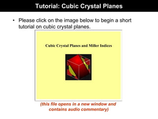
![Procedure: Find Direction Indices
(0,0,0)
(1,1/2,1)
z
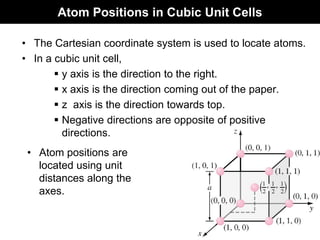
Extend the direction vector until it
emerges from the surface of cubic cell
Determine the coordinates of the
points of emergence and origin
Subtract coordinates of point of
emergence by that of origin
(1,1/2,1) - (0,0,0)
= (1,1/2,1)
Are all are
integers?
Convert them to
smallest possible
integer by multiplying
by an integer.
2 x (1,1/2,1)
= (2,1,2)
Are any of the direction
vectors negative?
Represent the indices in a square
bracket without comas with a
over negative index (Eg: [121])
Represent the indices in a square
bracket without comas (Eg: [212] )
The direction indices are [212]
x
y
YES
NO
YES
NO](https://image.slidesharecdn.com/materialsch3-230203201037-a7b9fe6d/85/Materials_Ch3-pdf-38-320.jpg)
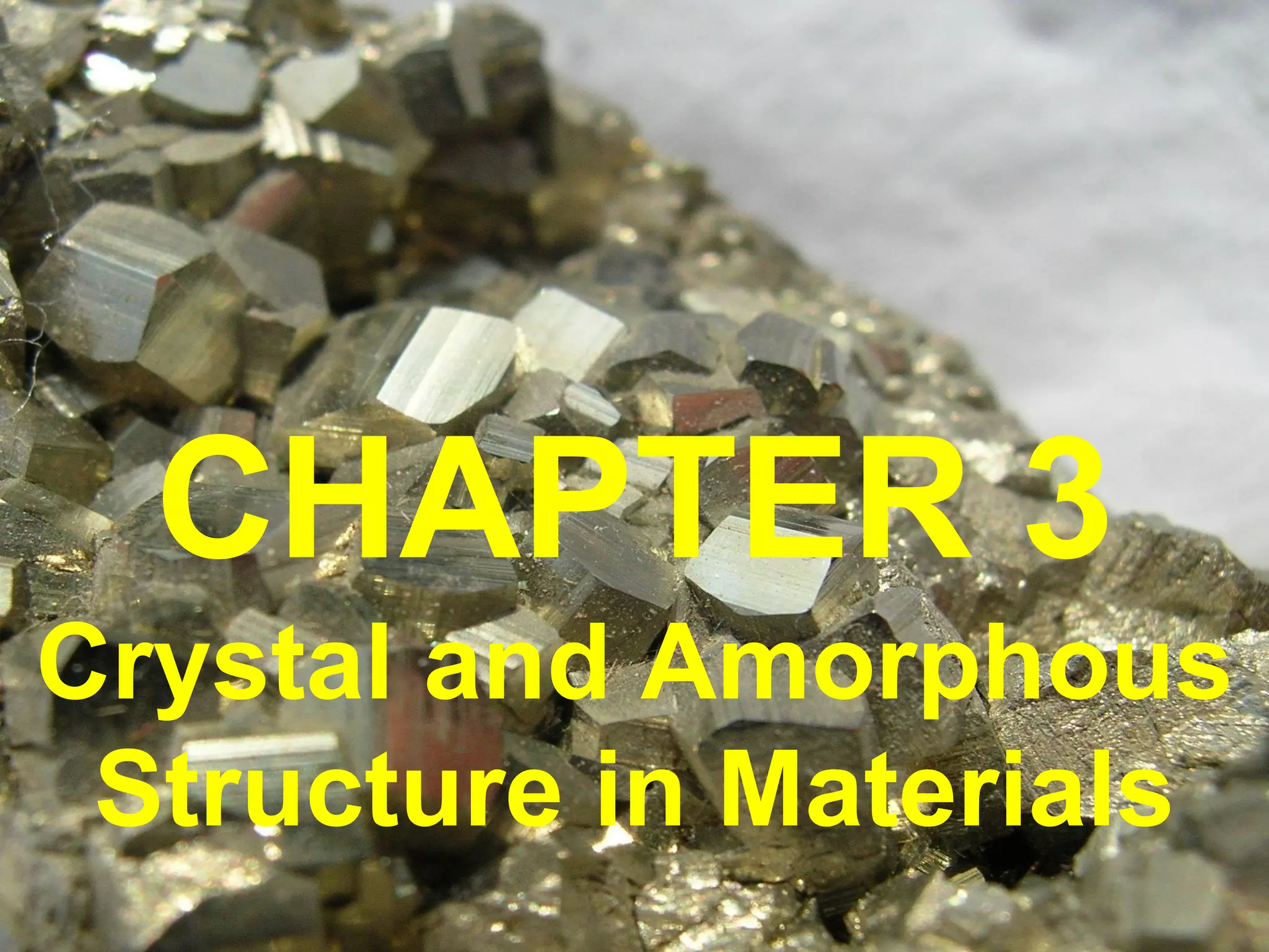
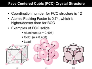
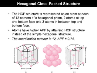
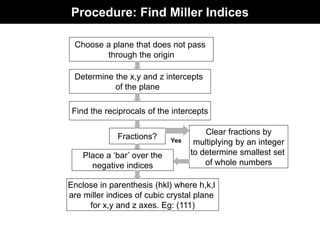
![Example: Direction Indices
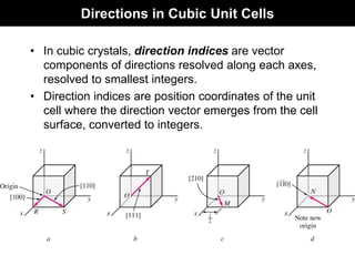
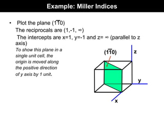
• Determine direction indices of the given vector.
Origin coordinates are (3/4 , 0 , 1/4).
Emergence coordinates are (1/4, 1/2, 1/2).
Subtract origin coordinates
from emergence coordinates,
(1/4, 1/2, 1/2) - (3/4 , 0 , 1/4)
= (-1/2, 1/2, 1/4)
Multiply by 4 to convert all
fractions to integers
4 x (-1/2, 1/2, 1/4) = (-2, 2, 1)
Therefore, the direction indices are [ 2 2 1 ]](https://image.slidesharecdn.com/materialsch3-230203201037-a7b9fe6d/85/Materials_Ch3-pdf-39-320.jpg)
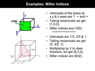
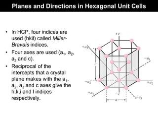
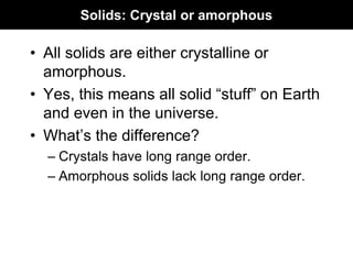
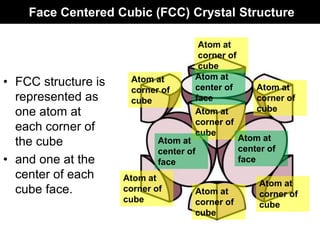
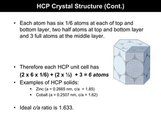
![Directions in HCP Unit Cells
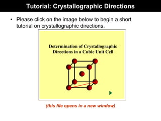
• Indicated by 4 indices [uvtw].
• u,v,t and w are lattice vectors in a1, a2, a3 and c directions
respectively.
• Example:
For a1, a2, a3 directions, the direction indices are
[ 2 1 1 0], [1 2 1 0] and [ 1 1 2 0] respectively.](https://image.slidesharecdn.com/materialsch3-230203201037-a7b9fe6d/85/Materials_Ch3-pdf-49-320.jpg)
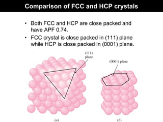
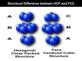
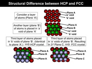
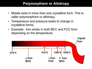
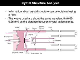
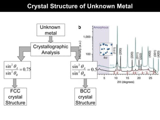

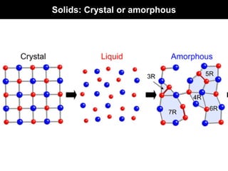
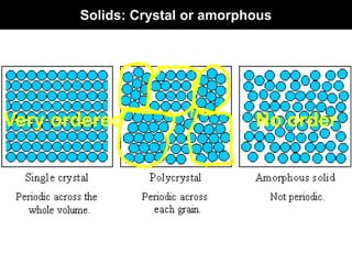
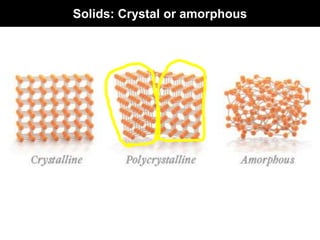
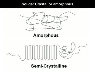
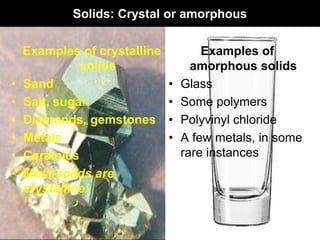
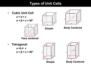
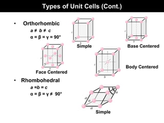
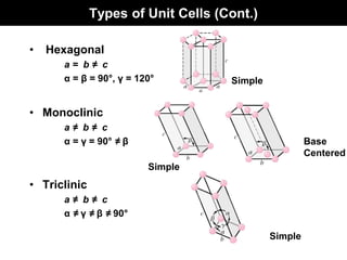
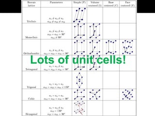
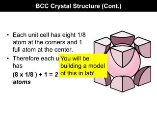
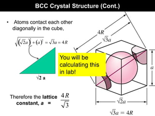
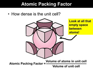
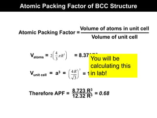
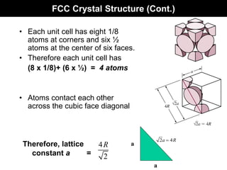
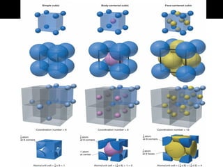
This document discusses crystal and amorphous structures in materials. It begins by defining crystals as having long-range order while amorphous solids lack long-range order. Examples of common crystalline and amorphous solids are provided. The document then goes into extensive detail about different types of unit cells and crystal structures including body centered cubic, face centered cubic, and hexagonal close packed. It discusses topics such as lattice constants, atomic packing factors, Miller indices, and crystallographic directions. Finally, it briefly discusses polymorphism and how x-ray diffraction can be used to analyze crystal structures.