This document provides design details and construction instructions for Versaloc retaining walls and basement walls. It includes:
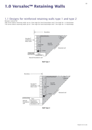
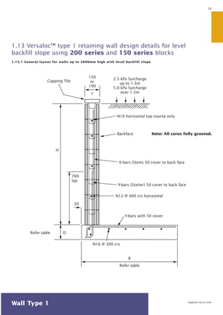
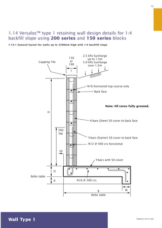
- Two wall types with different base designs for retaining level or sloped backfill up to 2.6m high.
- Soil classification and material specifications for backfill, retained soil, and foundation soil.
- Instructions on building the reinforced concrete base, installing starter bars, laying blocks, bracing, and grouting.
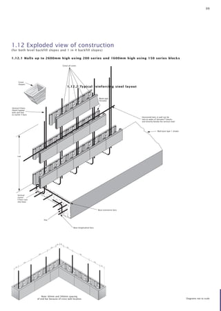
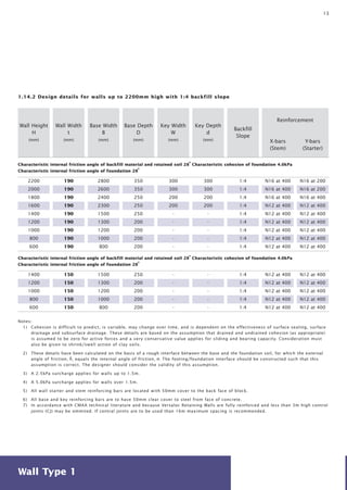
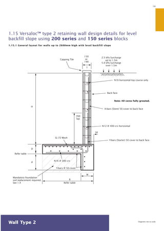
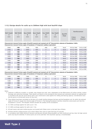
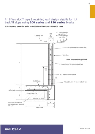
- Exploded views and design details for each wall type up to specified heights with level or sloped backfill.
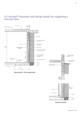
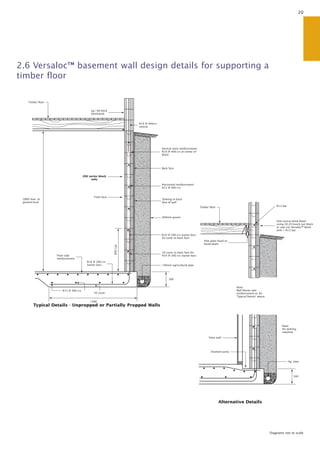
- Basement wall designs supporting concrete or timber floors up to 2.8m high.
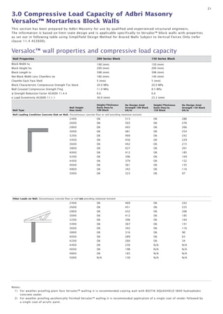
- A table with compressive load capacities for walls

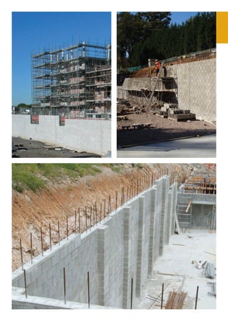


![CONSTRUCTION [soil treatment, foundation backfill, Damp Proof Membrane[DPM] a...](https://cdn.slidesharecdn.com/ss_thumbnails/kahimba-181220112907-thumbnail.jpg?width=640&height=640&fit=bounds)


