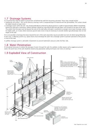
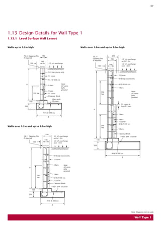
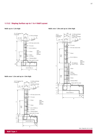
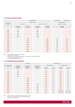
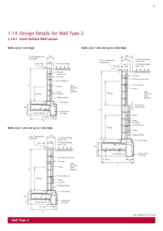
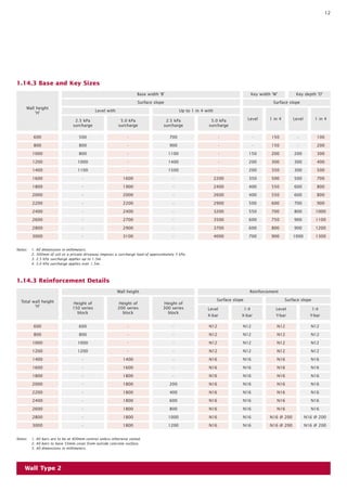
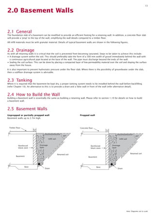
SlideShare a Scribd company logo
1 of 15
Download to read offline
AUSTRALIAN PAVING CENTRE
How to build a Besser Block Wall
Contents

Preface
Introduction
1.0 Retaining walls
1.1 Designs for reinforced retaining
wall types
1.2 Loading Conditions
1.2.1 Retaining Walls
1.3 Material Specifications
1.4 Soil Classification
1.5 Wall Foundation
1.6 Infill Soil and Retained Soil
1.7 Drainage Systems
1.8 Water Penetration
1.9 Exploded View of Construction
1.10 How to Build the Wall
1.10.1 Preliminary
1.10.2 Base and Hob
1.10.3 Block Laying
1.10.4 Grouting
1.11 Tanking
1.12 Infill Soil and Drainage
1.13 Design Details for Wall Type 1
1.13.1 Level Surface Wall Layout
1.13.2 Sloping Surface up to 1 in 4
Wall Layout
1.13.3 Base and Key Sizes
1.13.4 Reinforcement Details
1.14 Design Details for Wall Type 2
1.14.1 Level Surface Wall Layout
1.14.2 Sloping Surface up to 1 in 4
Wall Layout
1.14.3 Base and Key Sizes
1.14.4 Reinforcement Details
2.0 Basement Walls
2.1 General
2.2 Drainage
2.3 Tanking
2.4 How to build the wall
2.5 Designs for reinforced basement
wall types
2.6 Besser block basement wall
design details for supporting
a concrete floor
2.7 Besser block basement wall
design details for supporting
a timber floor
2.8 Basement walls
Glossary

Introduction

2
2
3
3
4
4
4
4
4
4
5
5
5
6
6
6
6
6
6
6
7
7
8
9
9
10
10
11
12
12
13
13
13
13
13
13

14

14
15
15

Preface
The designs shown in the brochure are based
on limit state design in accordance with the
provisions of AS4678-2002 Earth retaining
structures standard including Amendment
1, 2003. The designs are hereby certified by
Adbri Masonry Building Products Pty Ltd ABN
31 009 687 521.
The design details provided in this brochure
have been prepared by Adbri Masonry specifically
for Adbri Masonry blocks and are applicable
only to retaining walls using Adbri Masonry
products for residential or light commercial
applications up to 3.0m high. For higher and/or
more complex applications it is recommended
reference be made to the Concrete Masonry
Association of Australia document Reinforced
Concrete Masonry Cantilever Retaining Walls –
Design and Construction Guide MA51,
Amended July 2003.

Reinforced BESSER™ Block
Retaining and Basement
Walls consist of a reinforced
concrete base which anchors
the wall against overturning
and sliding, and a stem
of BESSER™ blocks.
The stem is reinforced with
steel bars placed vertically
and horizontally, and all cores
in the blocks are filled with
semi-fluid concrete, known as
‘grout’. The vertical reinforcing
bars in the cores are lapped
with shorter ‘starter bars’
embedded firmly in the
reinforced concrete base
using a hob to correctly
locate the bars. These short
bars allow easier block laying,
and the longer bars are put in
after all blocks are laid and
before grouting. The length of
the lap is critically important
and must be shown on the
drawings.
03

1.0 Retaining Walls

1.1 Designs for Reinforced Retaining Wall Types
Retaining walls up to 3.0m high.

Wall Type 1

Boundary

45º
Reinforced
block stem

Infill soil

Drainage
layer
Hob

Retained soil

Drain
Base

Wall Type 2

Boundary

45º
Reinforced
block stem

Infill soil

Drainage
layer
Hob
Retained soil
Base
Drain

Note: Diagrams not to scale
04

1.2 Loading Conditions 1.4 Soil Classification
1.2.1 Retaining Walls

1.4 Soil classification

These tables cover four loading conditions:
• Level surface with 2.5 kPa surcharge
for walls up to 1.5m high.
• Level surface with 5.0 kPa surcharge
for walls over 1.5m high.
• Sloping surface up to 1:4 with 2.5 kPa
surcharge for walls up to 1.5m high.
• Sloping surface up to 1:4 with 5.0 kPa
surcharge for walls over 1.5m high.

To simplify the following design tables only one type of soil has been used throughout
for both infill soil and retained soil. It is classified as an average soil and would be typical
of a wide range of insitu soils and would normally include; stiff sandy clays, gravelly
clays, compact clayey sand and sandy silts, compacted clay fill (Class II).

Notes:
• 300mm of soil or a private driveway
imposes a load of approximately 5 kPa.
• Sloping surface steeper than 1:4 is not
included in this brochure.

1.3 Material
Specifications
In calculating these tables, the following
material specifications were adopted:
BESSER™ Block
f’uc = 15 MPa in accordance with
AS 4455 - 1997
Mortar Class M3
Cement 1 : Lime 1 : Sand 6
OR Cement 1 : Lime 0 : Sand 5
plus cellulose-based water thickener
Concrete base
f’c =
25 MPa
Reinforcement
Grade 500 N
Grout
f’c =
20 MPa with a pourable
consistency and a cement
content no less than
300 kg/m3
Where possible, use ready-mixed grout and
specify when ordering that it is for filling
blockwork. If the grout is mixed on site,
use the following proportion:
Cement
1 part
Hydrated Lime
Up to 1/10th part
Mortar Sand
3 parts
10mm aggregate
Up to 2 parts
Notes:
• 10mm aggregate should be rounded
gravel where possible.
• Grout should be mixed in a tilting drum
paddle mixer and should flow freely
without separation of the aggregate.

The characteristic soil property has been reduced by the uncertainty factors below and
upon which the designs have been based:
Uncertainty factor for drained cohesion, = uc 0.70
Uncertainty factor for drained internal friction angle,
ie: * = tan-1 ( u (tan ‘))

u

Characteristic
soil parameters

= 0.85

Design
soil parameters

Internal friction angle
‘ (degrees)

Cohesion
c’ (kPa)

Internal friction angle
* (degrees)

Cohesion
c* (kPa)

27

3

23

2

1.5 Wall foundation
The tables have been based on a foundation soil as described above and which must
be excavated to sufficient depth to expose undisturbed material which is firm and dry.
Should a designer wish to analyse a retaining wall built on a different foundation, base
dimensions different from the tabulated values could be appropriate.
If any of the following foundation conditions exist: softness, poor drainage, filled ground,
organic matter, variable conditions, heavily cracked rock, aggressive soils, then experienced
professional engineering advice should be obtained.

1.6 Infill soil and retained soil
These tables have been calculated for infill soil and retained soil of soil classification
shown above.
Note: The following poor quality soils are not allowed for in the tables; soft and firm clay
of medium to high plasticity, silty clays, loose variable clayey fill, loose sandy silts.
If these soils are considered for use or aggressive groundwater exists an experienced
professional engineer should be consulted and separate designs be obtained.
05

1.7 Drainage Systems
It is essential that steps be taken to prevent the soil behind the wall from becoming saturated. These steps should include:
• Sealing the soil surface – this can be done by covering it with a compacted layer of material with low permeability. The surface should
be sloped towards an open drain.
• A drainage system within the soil – this should preferably be achieved by placing gravel to a width of approximately 300mm immediately
behind the wall with a continuous 100mm diameter slotted pvc agricultural pipe with geo fabric sock located at the base of the wall.
The outlets from the pipe must be beyond the ends of the wall unless the pipe is connected to a proper storm water drainage system.
For higher walls, or in cases where excessive ground water exists it may be necessary to provide another agricultural pipe drain at mid
height of the wall.
If it is not possible to discharge the drains beyond the end of the wall, weep-holes may be provided (see items for block laying following).
In this case, a collecting system (e.g. spoon drains) must discharge the water into a drainage system to prevent saturation of the ground
in front of the wall.
A subfloor drainage system is advisable in basements to prevent hydrostatic pressure under the floor slab.

1.8 Water Penetration
If considered necessary to reduce the passage of water through the wall, for aesthetic or other reasons such as aggressive ground
water, the earth face of the wall should be treated using appropriate sealing techniques (see notes on tanking.)

1.9 Exploded View of Construction
Grout all cores
Grout
Hopper

Note:
Where 15.42 or 20.42 blocks are
in lieu of 20.48 blocks, lay alternative
courses inverted and support horizontal
reinforcement in the centre of the wall
and 20 mm clear of the webs.
Blocks type
20.48

Vertical X-bars
(Stem) lapped
with and tied to
starter Y-bars
Horizontal bars
in wall can be laid
on webs of H-blocks.
Wall base

Cleanout
Blocks 20.61
or 20.45
Lap
Position vertical X and
Y-bars to give 55mm
clear cover on earth side.

Cleanout
Block 20.45

Vertical starter
Y-bars cast
into base

Formwork to close cleanout
openings. Tie to vertical bars
with wire or support with
temporary timber struts.

Hob
Base transverse bars
Base longitudinal bars

Cleanout
Biscuit 20.45A

Key

Note: Diagrams not to scale
06

1.10 How to Build the Wall
1.10.1 Preliminary
• Excavate to a satisfactory foundation.
• Arrange for supply of materials to the specifications given previously.

1.10.2 Base and hob
• Form the base and hob to the required dimensions and levels as shown in tables.
• Place the base reinforcement as shown in the diagrams, securely fix the starter bars for the vertical reinforcement (Y-bars) 55mm from
the back face of the wall, in the correct positions relative to the block cores to be reinforced by using the top front edge of the hob
as a positioning reference point.
• Place the base concrete, preferably using ready-mixed concrete, and compact thoroughly by rodding, spading or vibrating.
Wood float finish any surface to be exposed permanently. Take care not to dislodge reinforcement.

1.10.3 Block laying
Block laying procedure follows that of the normal practice for building unreinforced walls but, includes the additional requirement of locating the
first course directly on top of a hob which is used to accurately locate the starter bars. The mortar mix used should be cement 1 part, lime 1 part,
sand 6 parts or cement 1 part, sand 5 parts plus water thickener. These parts should be accurately measured by volume (e.g. a bucket). The sand
used should be clean pit sand, masonry or plasterer’s sand. The use of plasticising additives is permitted. Where they are used, the dosage
rate must not exceed that recommended by the supplier as this will drastically reduce the mortar strength. Detergent should never be used.
Recommendations specifically applicable to reinforced concrete block retaining walls follow:
• Cleanout openings should be provided in the bottom course using either 20.61 blocks plus timber formwork at the front or 20.45 blocks
plus 20.45 A biscuits to permit removal of mortar fins and other debris, and to allow positioning and tying of vertical reinforcement.
These openings must be closed before grouting.
• Above the first course, the use of 15.48, 20.48 and 30.48 H-Blocks is recommended because they are easier to fill with grout and provide
required protection of the reinforcement. 15.42 and 20.42 blocks may be used in lieu of H-Blocks and these blocks require less grout for filling.
However, they must be laid with alternative courses inverted so as to provide grout cover to longitudinal reinforcement, which must be lifted
20mm clear of the web of the block by using stirrups or other supports (see diagram).
• Mortar projecting into the cores should be removed, either as the blocks are laid, or by rodding after the mortar has set. Debris should
be removed from the cores through the cleanout openings.
• When the wall is to be tanked, the mortar joints on that face should be struck flush and cleaned.
• Weepholes can be providing by passing 50mm diameter upvc pipes holes through the hob at 1200mm centres.
• Reinforcement must be positioned accurately (refer to above), and tied securely before placing concrete or grout. Vertical reinforcing bars,
including starter bars, should be as close to the back face of the wall as possible, consistent with 55mm cover requirements.

1.10.4 Grouting
• Close cleanout openings.
• Place grout. It is recommended that whenever available, ready-mixed grout to workability specifications given in AS3700 2001 should be used.
Site-mixed grout, if used, should be mixed thoroughly in a tilting drum type paddle mixer to the same specification as ready-mixed grout.
• All cores should be filled with grout, whether reinforced or not. This is essential to bond and protect horizontal reinforcement, and
to give maximum weight for stability.
• The grout should be compacted thoroughly so that voids are not left. Compaction may be by rodding with a plain round bar
(do not use main vertical reinforcing bars or other deformed bars) or with a high frequency pencil vibrator, used carefully.
• We recomend using “Coremasta” for corefilling your walls. “Coremasta” is a specially formulated block filler that gives superior grout
penetration and requires minimal labour hours. Contact Hanson Construction Materials on 132 662 for more details.

1.11Tanking
Where the wall is required to be waterproof, for example a basement wall, various proprietary tanking methods are available. One such
method is a three coat liquid rubber compound incorporating a special reinforcing fabric for high stressed areas.
Another method is a heavy duty, pliable, waterproof sheet membrane fixed to the wall surface. Surface coatings or sheet membranes
must always be used in accordance with the manufacturer’s specifications.

1.12 Infill Soil and Drainage
• Infill soil should not placed behind the wall until at least ten days after grouting.
• Infill soil should be placed and compacted in layers not more than 200mm deep. The degree and method of compaction depends
on the proposed use of the retaining wall.
• The drainage system should be installed progressively as the infill soil rises.
• The drainage system behind the wall should be connected to the main drainage system.
• For the nominated infill soil in this brochure, it is advisable to seal off the top surface of the infill soil with a semi-impermeable layer
of soil or earth. Compact and grade to a gutter to provide surface drainage.
07

1.13 Design Details for Wall Type 1
1.13.1 Level Surface Wall Layout
Walls up to 1.2m high

Walls over 1.8m and up to 3.0m high

75.10 Capping Tile
if required

190

10.31
Capping Tile
if required

140
2.5 kPa surcharge

100

340
290
190

100

2.5 kPa surcharge
up to 1.5m
5.0 kPa surcharge
over 1.5m

N16 top course only
55 cover

55 cover

N16 top course only

N12 @ 400 crs
H

Note:
All cores
fully
grouted

X-bars

Y-bars
500 lap

N12 @ 400 crs
X-bars
Note:
All cores
fully
grouted

700
lap

55 cover
Cleanout Block
Y-bars with
55 cover

100

55 cover to
top of Y-bars

200
H
N16 @ 300 crs

Y-bars

B

700
lap

Walls over 1.2m and up to 1.8m high

Y-bars
55 cover
N16 @ 400 crs
X-bars
Cleanout Block

240
2.5 kPa surcharge
up to 1.5m

10.31 Capping Tile
if required
190

5.0 kPa surcharge
over 1.5m

100

Y-bars with 55 cover
100
350

N16 @ 300 crs
N16 top course only

B

55 cover
X-bars
H

Note:
All cores
fully
grouted

Y-bars

700
lap

N12 @ 400 crs
55 cover
Cleanout Block
Y-bars with 55 cover

100
250

N16 @ 300 crs
B

Note: Diagrams not to scale

Wall Type 1
07

1.13.2 Sloping Surface up to 1 in 4 Wall Layout
Walls up to 1.2m high

75.10 Capping Tile
if required

Walls over 1.8m and up to 3.0m high

340

190

10.31
Capping Tile
if required

2.5 kPa surcharge
140

100
100

290

2.5 kPa surcharge
up to 1.5m
5.0 kPa surcharge
over 1.5m

190

N16 top course only
55 cover

55 cover

N16 top course only

N12 @ 400 crs
H

Note:
All cores
fully
grouted

X-bars
Y-bars
55 cover

500
lap

X-bars
700
lap

N12 @ 400 crs

Cleanout Block
Y-bars with 55 cover
100
55 cover to
top of Y-bars

200

Note:
All cores
fully
grouted

H
N16 @ 300 crs

Y-bars

B

700
lap

Walls over 1.2m and up to 1.8m high

Y-bars
55 cover
N16 @ 400 crs
X-bars

10.31 Capping Tile
if required

Cleanout Block

2.5 kPa surcharge
up to 1.5m

240

Y-bars with 55 cover

5.0 kPa surcharge
over 1.5m

190

100

100
350

D

N16 @ 300 crs

N16 top course only
W

55 cover
B
X-bars

Note:
All cores
fully
grouted

H
Y-bars
700
lap

N12 @ 400 crs
55 cover
Cleanout Block
Y-bars with 55 cover

100
250
D

N16 @ 300 crs

W
B
Note: Diagrams not to scale

Wall Type 1
09

1.13.3 Base and Key Sizes
Key width ‘W’

Base width ‘B’
Surface slope
Wall height
‘H’

Key depth ‘D’

Surface slope

Level with

Up to 1 in 4 with

Up to 1 in 4 with

2.5 kPa
surcharge

2.5 kPa
surcharge

5.0 kPa
surcharge

600

500

-

700

-

-

-

800

600

-

800

-

-

-

1000

700

-

1000

-

-

-

1200

850

-

1200

-

-

-

1400

1000

-

1400

-

-

-

1600

-

1300

-

1800

200

200

1800

-

1450

-

2200

200

250

2000

-

1650

-

2400

300

250

2200

-

1800

-

2700

300

300

2400

-

2000

-

2900

300

300

2600

-

2100

-

3200

300

350

2800

-

2250

-

3400

300

350

3000
Notes:

5.0 kPa
surcharge

-

2450

-

3700

300

400

1.
2.
3.
4.
5.

5.0 kPa
surcharge

No key required for level surface slope walls.
All dimensions in millimeters.
300mm of soil or a private driveway imposes a surcharge load of approximately 5 kPa.
2.5 kPa surcharge applies up to 1.5m.
5.0 kPa surcharge applies over 1.5m.

1.13.4 Reinforcement Details
Wall height
Total wall height
‘H’

600

Reinforcement

Height of
150 series
block

Height of
200 series
block

Height of
300 series
block

600

-

Surface slope

Surface slope

Level

1:4

Level

1:4

X-bar

X-bar

Y-bar

Y-bar

-

N12

N12

N12

N12

800

-

-

N12

N12

N12

N12

1000

-

-

N12

N12

N12

N12

1200

1200

-

-

N12

N12

N12

N12

1400

-

1400

-

N16

N16

N16

N16

1600

-

1600

-

N16

N16

N16

N16

1800

-

1800

-

N16

N16

N16

N16

2000

-

1800

200

N16

N16

N16

N16

2200

-

1800

400

N16

N16

N16

N16

2400

-

1800

600

N16

N16

N16

N16

2600

-

1800

800

N16

N16

N16

N16

2800

-

1800

1000

N16

N16

N16 @ 200

N16 @ 200

3000
Notes:

800

1000

-

1800

1200

N16

N16

N16 @ 200

N16 @ 200

1. All bars are to be at 400mm centres unless otherwise stated.
2. All bars to have 55mm cover from outside concrete surface.
3. All dimensions in millimeters.

Wall Type 1
10

1.14 Design Details for Wall Type 2
1.14.1 Level Surface Wall Layout
Walls up to 1.2m high

Walls over 1.8m and up to 3.0m high

75.10 Capping Tile
if required

340

190

140

10.31 Capping Tile
if required

2.5 kPa surcharge

100

290

2.5 kPa surcharge
up to 1.5m
5.0 kPa surcharge
over 1.5m

190
100

N16 top
course only

55 cover

55 cover

N16 top course only
N12 @ 400 crs
H

X-bars

Y-bars
55 cover

500 lap

N12 @ 400 crs

Note:
All cores
fully
grouted

X-bars
Note:
All cores
fully
grouted

700 lap

Cleanout Block
SL72 Mesh

100

55 cover to
top of Y-bars

200
H
D

Y-bars with
55 cover

N16 @ 300 crs

Y-bars
55 cover

W
Y-bars
55 cover

B

N16 @ 400 crs
700 lap

Walls over 1.2m and up to 1.8m high

X-bars

10.31 Capping Tile
if required

Cleanout Block

240
2.5 kPa surcharge
up to 1.5m
190

100

SL72 mesh

100

5.0 kPa surcharge
over 1.5m
350

D

Y-bars with
55 cover

N16 @ 300 crs

N16 top course only
55 cover

W

55 cover
X-bars
H

Note:
All cores
fully
grouted

B

N12 @ 400 crs
700 lap

Y-bars
55 cover
Cleanout Block

SL72 mesh

100
250
D

Y-bars with
55 cover

N16 @ 300 crs
55 cover

W

B
Note: Diagrams not to scale

Wall Type 2
11

1.14.2 Sloping Surface up to 1 in 4 Wall Layout
Walls up to 1.2m high

Walls over 1.8m and up to 3.0m high

75.10 Capping Tile
if required

190

2.5 kPa surcharge
up to 1.5m

340
10.31
Capping Tile
if required

2.5 kPa
surcharge

140

290

100

5.0 kPa surcharge
over 1.5m

190
100
N16 top
course only
55 cover

55 cover

N16 top course only

N12 @ 400 crs
H

X-bars

Y-bars
55 cover

500 lap

Note:
All cores
fully
grouted

Note:
All cores
fully
grouted

X-bars
700 lap

N12 @ 400 crs

Cleanout Block
SL72 Mesh

100

55 cover to
top of Y-bars

200
D

H

Y-bars with
55 cover

N16 @ 300 crs

Y-bars
55 cover

W
Y-bars
55 cover

B

N16 @ 400 crs
700 lap

Walls over 1.2m and up to 1.8m high

X-bars

10.31 Capping Tile
if required

Cleanout Block

2.5 kPa surcharge
up to 1.5m

240

5.0 kPa surcharge
over 1.5m

190

SL72 mesh

100

100
350

D

N16 @ 300 crs

Y-bars with
55 cover

N16 top course only
55 cover

W

55 cover
B
X-bars
H

Note:
All cores
fully
grouted

N12 @ 400 crs
Y-bars
55 cover

700 lap

Cleanout Block

SL72 mesh

100
250
D

Y-bars with
55 cover

N16 @ 300 crs
55 cover
W
B

Note: Diagrams not to scale

Wall Type 2
12

1.14.3 Base and Key Sizes
Key width ‘W’

Base width ‘B’
Surface slope
Wall height
‘H’

Key depth ‘D’

Surface slope

Level with

Up to 1 in 4 with

2.5 kPa
surcharge

2.5 kPa
surcharge

5.0 kPa
surcharge

Level

1 in 4

Level

1 in 4

600

500

-

700

-

-

150

-

100

800

800

-

900

-

-

150

-

200

1000

800

-

1100

-

150

200

200

300

1200

1000

-

1400

-

200

300

300

400

1400

1100

-

1500

-

200

350

300

500

1600

-

1600

-

2200

350

500

500

700

1800

-

1900

-

2400

400

550

600

800

2000

-

2000

-

2600

400

550

600

800

2200

-

2200

-

2900

500

600

700

900

2400

-

2400

-

3200

550

700

800

1000

2600

-

2700

-

3500

600

750

900

1100

2800

-

2900

-

3700

600

800

900

1200

3000
Notes:

5.0 kPa
surcharge

-

3100

-

4000

700

900

1000

1300

1.
2.
3.
4.

All dimensions in millimeters.
300mm of soil or a private driveway imposes a surcharge load of approximately 5 kPa.
2.5 kPa surcharge applies up to 1.5m.
5.0 kPa surcharge applies over 1.5m.

1.14.3 Reinforcement Details
Wall height
Total wall height
‘H’

600

Reinforcement

Height of
150 series
block

Height of
200 series
block

Height of
300 series
block

600

-

Surface slope

Surface slope

Level

1:4

Level

1:4

X-bar

X-bar

Y-bar

Y-bar

-

N12

N12

N12

N12

800

-

-

N12

N12

N12

N12

1000

-

-

N12

N12

N12

N12

1200

1200

-

-

N12

N12

N12

N12

1400

-

1400

-

N16

N16

N16

N16

1600

-

1600

-

N16

N16

N16

N16

1800

-

1800

-

N16

N16

N16

N16

2000

-

1800

200

N16

N16

N16

N16

2200

-

1800

400

N16

N16

N16

N16

2400

-

1800

600

N16

N16

N16

N16

2600

-

1800

800

N16

N16

N16

N16

2800

-

1800

1000

N16

N16

N16 @ 200

N16 @ 200

3000
Notes:

800

1000

-

1800

1200

N16

N16

N16 @ 200

N16 @ 200

1. All bars are to be at 400mm centres unless otherwise stated.
2. All bars to have 55mm cover from outside concrete surface.
3. All dimensions in millimeters.

Wall Type 2
13

2.0 Basement Walls

2.1 General
The foundation slab of a basement can be modified to provide an efficient footing for a retaining wall. In addition, a concrete floor slab
will provide a ‘prop’ to the top of the wall, simplifying the wall details compared to a timber floor.
All infill materials must be with granular material. Details of typical basement walls are shown in the following figures.

2.2 Drainage
As with all retaining walls it is critical that the soil is prevented from becoming saturated. Steps to be taken to achieve this include:
• A drainage system within the soil. This should preferably take the form of a 300 mm width of gravel immediately behind the wall with
a continuous agricultural pipe located at the base of the wall. The pipe must discharge beyond the ends of the wall.
• Sealing the soil surface. This can be done by placing a compacted layer of low-permeability material over the soil and sloping the surface
away from the house.
It is also important to prevent hydrostatic pressure under the floor slab. Where there is the possibility of groundwater under the slab,
then a subfloor drainage system is advisable.

2.3 Tanking
Where it is required that the basement be kept dry, a proper tanking system needs to be installed behind the wall before backfilling
(refer Chapter 10). An alternative to this is to provide a drain and a false wall in front of the wall (refer alternative detail).

2.4 How to Build the Wall
Building a Basement wall is essentially the same as building a retaining wall. Please refer to section 1.10 for details on how to build
a basement wall.

2.5 Basement Walls
Unpropped or partially propped wall
Basement walls up to 2.7m high.

Propped wall

Timber floor

Concrete floor

45º

45º

Infill soil

Reinforced
block stem

Drainage
layer

Reinforced
block stem

Drainage
layer
Retained soil

Retained soil

Basement

Base

Infill soil

Basement

Drain

Base

Drain

Note: Diagrams not to scale
14

2.6 BESSER™ Block Basement Wall Design Details
For Supporting a Concrete Wall
Typical details - Fully-propped walls

Alternative details
Starter bar to match
wall reinforcement
above

N12 at 200 crs

Floor slab
reinforcement

One-course bond beam
with N12 bar
20.20 knock-out block
saw-cut at floor soffit level

20.48 ‘H’ blocks

Horizontal reinforcement
N12 at 400 crs
Tanking to back face
of wall

Note:
Wall blocks and reinforcement as for
‘Typical Details’ - fully propped walls

2700 max.
190 thick
blockwork

Vertical reinforcement
N16 at 400 crs, central

Note:
No tanking
required

Note:
N12 at 200 crs
may be used
instead of N16
at 400 crs

False wall
Ag. drain
Floor slab
reinforcement

N16 at
400 crs

Drained cavity
Ag. drain
200
200

N12 at 400 crs

55 cover
1000

2.7 BESSER™ Block Basement Wall Design Details
For Supporting a Timber Floor
Typical details - Unpropped or partially-propped walls

Timber floor

Alternative details

Timber floor

140-thick
blockwork

One-course bond beam
using 20.20 knock-out block
with 1-N12 bar
Pole plate fixed
to bond beam
Vertical reinforcement
N16 at 400 crs, central

20.48 ‘H’ blocks

190-thick
blockwork

Horizontal reinforcement
N12 at 400 crs
55 cover to back face

Note:
Reinforcement as for ‘Typical Details’

190 thick
blockwork

2700 max. to
ground level

290-thick
blockwork
290 thick
blockwork

Tanking to back face
of wall

55 cover to back face

Note:
N20 at 400 crs
may be used
instead of N16
at 200 crs

1200

False wall
30.48 ‘H’ blocks

Floor slab
reinforcement

Ag. drain
Drained cavity

N16 at
200 crs

Ag. drain

300
N12 at 400 crs

Note:
No tanking
required

300

55 cover

1500

Note: Diagrams not to scale
Glossary

2.8 Basement Walls
These designs are based on a level surface
with 5 kPa surcharge. Walls designed as propped
must not be backfilled before the concrete
floor at the top of the wall is in place.

Important Notes
No loadings should be applied (e.g. from footings),
within the area of infill soil other than those
loadings referred to above.
The area of infill soil is bounded by a line at 45°
to the rear of the base as illustrated in chapter 1.
Only one typical soil case is presented.
These tables may not provide an ideal solution
in a particular case.
For situations other than those covered by the
tables, or if there is doubt as to:
• The strength and stability of the foundation
material the drainage system needed
• An experienced professional engineer should
be consulted for advice.

Flinders Park
284 Grange Road, Flinders Park, SA 5025
phone: (08) 8234 7144 I fax: (08) 8234 9644
Gawler
Cnr Main North & Tiver Rd, Evanston, SA 5116
phone: (08) 8522 2522 I fax: (08) 8522 2488
Gepps Cross
700 Main North Road, Gepps Cross, SA 5094
phone: (08) 8349 5311 I fax: (08) 8349 5833
Holden Hill
578 North East Road, Holden Hill, SA 5088
phone: (08) 8369 0200 I fax: (08) 8266 6855
Kadina
86 Port Road, Kadina, SA 5554
phone: (08) 8821 2077 | fax: (08) 8821 2977

Load and Limit States:
Dead load*
The self-weight of the structure, infill soil, retained soil or rock.
Live load*
Loads that arise from the intended use of the structure, including
distributed, concentrated, impact and inertia loads. It includes
construction loads, but excludes wind and earthquake loads.
Surcharge
A uniformaly distributed external load. For retaining walls under 1.5m
a minimum load of 2.5 kPa. For retaining walls over 1.5m a minimum
load of 5 kPa.
Stability limit state
A limit state of loss of static equilibrium of a structure or part thereof,
when considered as a rigid body.
Strength limit state
A limit state of collapse or loss of structural integrity of the components
of the retaining wall.
Serviceability limit state
A limit state for acceptable in-service conditions. The most common
serviceability states are excessive differential settlement and forward
movement of the retaining wall.

Components:
Concrete masonry units
Concrete blocks manufactured to provide an attractive, durable, stable
face to a retaining wall. The recommended block types are the 15.48,
20.48 and 30.48 ‘H’ blocks.
Retained soil
The natural soil, intended to be retained by a retaining wall.
Foundation soil
The natural soil material under a retaining wall.
Infill soil
The soil material placed behind the retaining wall facing. Often retained
soil is used for this purpose.

Lonsdale
13 Sherriffs Road, Lonsdale, SA 5160
phone: (08) 8381 2400 I fax: (08) 8381 2366
Mount Barker
4 Oborn Road, Mount Barker, SA 5251
phone: (08) 8391 3467 fax: (08) 8398 2518
Mount Gambier
6 Graham Road, Mount Gambier West, SA 5291
phone: (08) 8725 6019 I fax: (08) 8725 3724
Hallet Cove
9-11 Commercial Road, Sheidow Park, SA 5158
phone: (08) 8381 9142 I fax: (08) 8381 7666
Streaky Bay
18 Bay Road, Streaky Bay, SA 5680
phone: (08) 8626 7011 I mob: 0427 263 050

Westbourne Park
455 Goodwood Rd, Westbourne Park, SA 5041
phone: (08) 8299 9633 I fax: 08) 8299 9688
Whyalla
132 Norrie Ave, Whyalla Norrie, SA 5608
phone: (08) 8644 0918 I mob: 0412 810 056

* This brochure uses the terminology ‘dead load’ to indicate permanent
loads and ‘live load’ to indicate imposed loads. This terminology is
consistent with the convention adopted in AS 4678-2002.

More Related Content

What's hot (20)

Pointing by mani
Pointing by maniPointing by mani
Pointing by mani
 
How to build a besser block wall - APC
How to build a besser block wall - APCHow to build a besser block wall - APC
How to build a besser block wall - APC
 
Mat Foundation
Mat FoundationMat Foundation
Mat Foundation
 
Diaphragm Wall Presentation By Gagan
Diaphragm Wall Presentation By GaganDiaphragm Wall Presentation By Gagan
Diaphragm Wall Presentation By Gagan
 
Coffer Dams and Caissons
Coffer Dams and CaissonsCoffer Dams and Caissons
Coffer Dams and Caissons
 
Retaining walls
Retaining wallsRetaining walls
Retaining walls
 
pile wall
pile wallpile wall
pile wall
 
waterproofing
waterproofingwaterproofing
waterproofing
 
Mat or Raft Foundation, AUST O29+30 Sec-C
Mat or Raft Foundation, AUST O29+30 Sec-CMat or Raft Foundation, AUST O29+30 Sec-C
Mat or Raft Foundation, AUST O29+30 Sec-C
 
detailed specification for cement concrete
detailed specification for cement concretedetailed specification for cement concrete
detailed specification for cement concrete
 
Foundation
FoundationFoundation
Foundation
 
1.2 Diaphragm walls.pptx
1.2 Diaphragm walls.pptx1.2 Diaphragm walls.pptx
1.2 Diaphragm walls.pptx
 
Predimensionamiento de elementos estructurales
Predimensionamiento de elementos estructuralesPredimensionamiento de elementos estructurales
Predimensionamiento de elementos estructurales
 
Retaining wall
Retaining wallRetaining wall
Retaining wall
 
Details of roofs and floors
Details of roofs and floorsDetails of roofs and floors
Details of roofs and floors
 
Foundation and its types
Foundation and its typesFoundation and its types
Foundation and its types
 
Diaphragm wall construction
Diaphragm wall constructionDiaphragm wall construction
Diaphragm wall construction
 
Retaining walls
Retaining wallsRetaining walls
Retaining walls
 
SHALLOW FOUNDATION
SHALLOW FOUNDATIONSHALLOW FOUNDATION
SHALLOW FOUNDATION
 
Construction of diaphragm wall
Construction of diaphragm wallConstruction of diaphragm wall
Construction of diaphragm wall
 

Viewers also liked

Ancon Wall Ties and Restraint Fixings for Brick, Block and Stone
Ancon Wall Ties and Restraint Fixings for Brick, Block and StoneAncon Wall Ties and Restraint Fixings for Brick, Block and Stone
Ancon Wall Ties and Restraint Fixings for Brick, Block and StoneLBS Builders Merchants
 
besser block retaining wall
besser block retaining wallbesser block retaining wall
besser block retaining wallkristenjames
 
Centre for the Creative Arts and Media (CCAM) | GMIT General Arrangment Drawings
Centre for the Creative Arts and Media (CCAM) | GMIT General Arrangment DrawingsCentre for the Creative Arts and Media (CCAM) | GMIT General Arrangment Drawings
Centre for the Creative Arts and Media (CCAM) | GMIT General Arrangment DrawingsJonathan Flanagan
 
Mark Thornton Portfolio
Mark Thornton PortfolioMark Thornton Portfolio
Mark Thornton PortfolioMark Thornton
 
1515-T_Drawings
1515-T_Drawings1515-T_Drawings
1515-T_DrawingsMark Daly
 
Structural engineer s pocket book
Structural engineer s pocket bookStructural engineer s pocket book
Structural engineer s pocket bookThomas Britto
 
Cavity Walling
Cavity WallingCavity Walling
Cavity WallingDjCurrie
 

Viewers also liked (11)

Ancon Wall Ties and Restraint Fixings for Brick, Block and Stone
Ancon Wall Ties and Restraint Fixings for Brick, Block and StoneAncon Wall Ties and Restraint Fixings for Brick, Block and Stone
Ancon Wall Ties and Restraint Fixings for Brick, Block and Stone
 
besser block retaining wall
besser block retaining wallbesser block retaining wall
besser block retaining wall
 
Centre for the Creative Arts and Media (CCAM) | GMIT General Arrangment Drawings
Centre for the Creative Arts and Media (CCAM) | GMIT General Arrangment DrawingsCentre for the Creative Arts and Media (CCAM) | GMIT General Arrangment Drawings
Centre for the Creative Arts and Media (CCAM) | GMIT General Arrangment Drawings
 
Mark Thornton Portfolio
Mark Thornton PortfolioMark Thornton Portfolio
Mark Thornton Portfolio
 
Construction, Chemicals and Waterproofing
Construction, Chemicals and Waterproofing Construction, Chemicals and Waterproofing
Construction, Chemicals and Waterproofing
 
Groundworks and Civil Engineering Products
Groundworks and Civil Engineering ProductsGroundworks and Civil Engineering Products
Groundworks and Civil Engineering Products
 
1515-T_Drawings
1515-T_Drawings1515-T_Drawings
1515-T_Drawings
 
Structural engineer s pocket book
Structural engineer s pocket bookStructural engineer s pocket book
Structural engineer s pocket book
 
Masonry Components
Masonry ComponentsMasonry Components
Masonry Components
 
Cavity Walling
Cavity WallingCavity Walling
Cavity Walling
 
Cavity walls
Cavity wallsCavity walls
Cavity walls
 

Similar to How to build a besser block wall

Btech compile 6 oct 4am
Btech compile 6 oct 4amBtech compile 6 oct 4am
Btech compile 6 oct 4amCeline Tan
 
Allan block Commercial brochure
Allan block Commercial brochureAllan block Commercial brochure
Allan block Commercial brochurekristenjames
 
Versaloc - very easy, very quick
Versaloc - very easy, very quickVersaloc - very easy, very quick
Versaloc - very easy, very quickkristenjames
 
Soldier Bored and Diaphragm
Soldier Bored and DiaphragmSoldier Bored and Diaphragm
Soldier Bored and DiaphragmYingHongKang
 
Lesson 3 Floor screeds _suspended floors.pptx
Lesson 3 Floor screeds _suspended floors.pptxLesson 3 Floor screeds _suspended floors.pptx
Lesson 3 Floor screeds _suspended floors.pptxsydneyaugust1
 
Specifications of rcc foundation
Specifications of rcc foundation Specifications of rcc foundation
Specifications of rcc foundation Prabhat chhirolya
 
EXCAVATION FOR FOUNDATION - Methods & Temporary Earth Retaining Structures
EXCAVATION FOR FOUNDATION - Methods & Temporary Earth Retaining StructuresEXCAVATION FOR FOUNDATION - Methods & Temporary Earth Retaining Structures
EXCAVATION FOR FOUNDATION - Methods & Temporary Earth Retaining StructuresShivananda Roy
 
Diaphragm walls
Diaphragm wallsDiaphragm walls
Diaphragm wallsNguyen Bao
 
Tutor cavity wall construction .ppt 1
Tutor cavity wall construction .ppt 1Tutor cavity wall construction .ppt 1
Tutor cavity wall construction .ppt 1Luke D'Arcy
 
6. FORMWORK (ACE) 2160601 GTU
6. FORMWORK (ACE) 2160601 GTU6. FORMWORK (ACE) 2160601 GTU
6. FORMWORK (ACE) 2160601 GTUVATSAL PATEL
 
CONSTRUCTION OF MULTI STOREY BUILDING.pptx
CONSTRUCTION OF MULTI STOREY BUILDING.pptxCONSTRUCTION OF MULTI STOREY BUILDING.pptx
CONSTRUCTION OF MULTI STOREY BUILDING.pptxVenkataRamana38198
 
RETAINING WALL
RETAINING WALLRETAINING WALL
RETAINING WALLYash Patel
 

Similar to How to build a besser block wall (20)

Versaloc (1)
Versaloc (1)Versaloc (1)
Versaloc (1)
 
Versaloc (1)
Versaloc (1)Versaloc (1)
Versaloc (1)
 
Btech compile 6 oct 4am
Btech compile 6 oct 4amBtech compile 6 oct 4am
Btech compile 6 oct 4am
 
Deep excavations
Deep excavationsDeep excavations
Deep excavations
 
Allan block Commercial brochure
Allan block Commercial brochureAllan block Commercial brochure
Allan block Commercial brochure
 
Versaloc - very easy, very quick
Versaloc - very easy, very quickVersaloc - very easy, very quick
Versaloc - very easy, very quick
 
Versaloc
VersalocVersaloc
Versaloc
 
Soldier Bored and Diaphragm
Soldier Bored and DiaphragmSoldier Bored and Diaphragm
Soldier Bored and Diaphragm
 
Pile foundation
Pile foundation Pile foundation
Pile foundation
 
Lesson 3 Floor screeds _suspended floors.pptx
Lesson 3 Floor screeds _suspended floors.pptxLesson 3 Floor screeds _suspended floors.pptx
Lesson 3 Floor screeds _suspended floors.pptx
 
Specifications of rcc foundation
Specifications of rcc foundation Specifications of rcc foundation
Specifications of rcc foundation
 
EXCAVATION FOR FOUNDATION - Methods & Temporary Earth Retaining Structures
EXCAVATION FOR FOUNDATION - Methods & Temporary Earth Retaining StructuresEXCAVATION FOR FOUNDATION - Methods & Temporary Earth Retaining Structures
EXCAVATION FOR FOUNDATION - Methods & Temporary Earth Retaining Structures
 
Diaphragm walls
Diaphragm wallsDiaphragm walls
Diaphragm walls
 
Diaphragm Wall
Diaphragm WallDiaphragm Wall
Diaphragm Wall
 
Tutor cavity wall construction .ppt 1
Tutor cavity wall construction .ppt 1Tutor cavity wall construction .ppt 1
Tutor cavity wall construction .ppt 1
 
6. FORMWORK (ACE) 2160601 GTU
6. FORMWORK (ACE) 2160601 GTU6. FORMWORK (ACE) 2160601 GTU
6. FORMWORK (ACE) 2160601 GTU
 
CONSTRUCTION OF MULTI STOREY BUILDING.pptx
CONSTRUCTION OF MULTI STOREY BUILDING.pptxCONSTRUCTION OF MULTI STOREY BUILDING.pptx
CONSTRUCTION OF MULTI STOREY BUILDING.pptx
 
Top Down Construction Presentation.
Top Down Construction Presentation.Top Down Construction Presentation.
Top Down Construction Presentation.
 
Interlocking pavement
Interlocking pavementInterlocking pavement
Interlocking pavement
 
RETAINING WALL
RETAINING WALLRETAINING WALL
RETAINING WALL
 

More from kristenjames

Yin and sound Immersion
Yin and sound ImmersionYin and sound Immersion
Yin and sound Immersionkristenjames
 
Melbourne boat hire proposal cruises
Melbourne boat hire proposal cruisesMelbourne boat hire proposal cruises
Melbourne boat hire proposal cruiseskristenjames
 
Residential Energy Audits
Residential Energy AuditsResidential Energy Audits
Residential Energy Auditskristenjames
 
Melbourne boat hire birrarung
Melbourne boat hire birrarungMelbourne boat hire birrarung
Melbourne boat hire birrarungkristenjames
 
Melbourne boat-hire-brochure-august-2018 (1)
Melbourne boat-hire-brochure-august-2018 (1)Melbourne boat-hire-brochure-august-2018 (1)
Melbourne boat-hire-brochure-august-2018 (1)kristenjames
 
Melbourne boat hire photography cruise flyer
Melbourne boat hire photography cruise flyerMelbourne boat hire photography cruise flyer
Melbourne boat hire photography cruise flyerkristenjames
 
HOW TO SET VIDEO ALARMS ON THE CONNECT APP
HOW TO SET VIDEO ALARMS ON THE CONNECT APPHOW TO SET VIDEO ALARMS ON THE CONNECT APP
HOW TO SET VIDEO ALARMS ON THE CONNECT APPkristenjames
 
The Present - Yoga Teacher Training
The	Present - Yoga Teacher TrainingThe	Present - Yoga Teacher Training
The Present - Yoga Teacher Trainingkristenjames
 
Yarra River Skippered Cruises and Private Boat Charter
Yarra River Skippered Cruises and Private Boat CharterYarra River Skippered Cruises and Private Boat Charter
Yarra River Skippered Cruises and Private Boat Charterkristenjames
 
Sound immersion on 22nd-December 2019 at UpDog Yoga
Sound immersion on 22nd-December 2019 at UpDog YogaSound immersion on 22nd-December 2019 at UpDog Yoga
Sound immersion on 22nd-December 2019 at UpDog Yogakristenjames
 
Vinyasa unlocked - UpDog Yoga
Vinyasa unlocked - UpDog YogaVinyasa unlocked - UpDog Yoga
Vinyasa unlocked - UpDog Yogakristenjames
 
Movement as medicine - UpDog Yoga
Movement as medicine - UpDog YogaMovement as medicine - UpDog Yoga
Movement as medicine - UpDog Yogakristenjames
 
Yoga studios melbourne updog yoga
Yoga studios melbourne  updog yogaYoga studios melbourne  updog yoga
Yoga studios melbourne updog yogakristenjames
 
Melbourne boat-hire-photography-cruise-flyer
Melbourne boat-hire-photography-cruise-flyerMelbourne boat-hire-photography-cruise-flyer
Melbourne boat-hire-photography-cruise-flyerkristenjames
 
Erectarack long span shelving-3
Erectarack long span shelving-3Erectarack long span shelving-3
Erectarack long span shelving-3kristenjames
 
Erectarack Raised Storage Areas
Erectarack Raised Storage Areas Erectarack Raised Storage Areas
Erectarack Raised Storage Areas kristenjames
 
Erectarack mezzanine Floor
Erectarack mezzanine FloorErectarack mezzanine Floor
Erectarack mezzanine Floorkristenjames
 
Banker and Jeweller Safes - CMI Premier
Banker and Jeweller Safes - CMI PremierBanker and Jeweller Safes - CMI Premier
Banker and Jeweller Safes - CMI Premierkristenjames
 
Ironguard Domestic Security Safe
Ironguard Domestic Security Safe Ironguard Domestic Security Safe
Ironguard Domestic Security Safe kristenjames
 

More from kristenjames (20)

Yin and sound Immersion
Yin and sound ImmersionYin and sound Immersion
Yin and sound Immersion
 
Melbourne boat hire proposal cruises
Melbourne boat hire proposal cruisesMelbourne boat hire proposal cruises
Melbourne boat hire proposal cruises
 
Residential Energy Audits
Residential Energy AuditsResidential Energy Audits
Residential Energy Audits
 
Melbourne boat hire birrarung
Melbourne boat hire birrarungMelbourne boat hire birrarung
Melbourne boat hire birrarung
 
Melbourne boat-hire-brochure-august-2018 (1)
Melbourne boat-hire-brochure-august-2018 (1)Melbourne boat-hire-brochure-august-2018 (1)
Melbourne boat-hire-brochure-august-2018 (1)
 
Melbourne boat hire photography cruise flyer
Melbourne boat hire photography cruise flyerMelbourne boat hire photography cruise flyer
Melbourne boat hire photography cruise flyer
 
HOW TO SET VIDEO ALARMS ON THE CONNECT APP
HOW TO SET VIDEO ALARMS ON THE CONNECT APPHOW TO SET VIDEO ALARMS ON THE CONNECT APP
HOW TO SET VIDEO ALARMS ON THE CONNECT APP
 
The Present - Yoga Teacher Training
The	Present - Yoga Teacher TrainingThe	Present - Yoga Teacher Training
The Present - Yoga Teacher Training
 
Yarra River Skippered Cruises and Private Boat Charter
Yarra River Skippered Cruises and Private Boat CharterYarra River Skippered Cruises and Private Boat Charter
Yarra River Skippered Cruises and Private Boat Charter
 
Sound immersion on 22nd-December 2019 at UpDog Yoga
Sound immersion on 22nd-December 2019 at UpDog YogaSound immersion on 22nd-December 2019 at UpDog Yoga
Sound immersion on 22nd-December 2019 at UpDog Yoga
 
Sound immersion
Sound immersionSound immersion
Sound immersion
 
Vinyasa unlocked - UpDog Yoga
Vinyasa unlocked - UpDog YogaVinyasa unlocked - UpDog Yoga
Vinyasa unlocked - UpDog Yoga
 
Movement as medicine - UpDog Yoga
Movement as medicine - UpDog YogaMovement as medicine - UpDog Yoga
Movement as medicine - UpDog Yoga
 
Yoga studios melbourne updog yoga
Yoga studios melbourne  updog yogaYoga studios melbourne  updog yoga
Yoga studios melbourne updog yoga
 
Melbourne boat-hire-photography-cruise-flyer
Melbourne boat-hire-photography-cruise-flyerMelbourne boat-hire-photography-cruise-flyer
Melbourne boat-hire-photography-cruise-flyer
 
Erectarack long span shelving-3
Erectarack long span shelving-3Erectarack long span shelving-3
Erectarack long span shelving-3
 
Erectarack Raised Storage Areas
Erectarack Raised Storage Areas Erectarack Raised Storage Areas
Erectarack Raised Storage Areas
 
Erectarack mezzanine Floor
Erectarack mezzanine FloorErectarack mezzanine Floor
Erectarack mezzanine Floor
 
Banker and Jeweller Safes - CMI Premier
Banker and Jeweller Safes - CMI PremierBanker and Jeweller Safes - CMI Premier
Banker and Jeweller Safes - CMI Premier
 
Ironguard Domestic Security Safe
Ironguard Domestic Security Safe Ironguard Domestic Security Safe
Ironguard Domestic Security Safe
 

Recently uploaded

Cash Payment 9602870969 Escort Service in Udaipur Call Girls
Cash Payment 9602870969 Escort Service in Udaipur Call GirlsCash Payment 9602870969 Escort Service in Udaipur Call Girls
Cash Payment 9602870969 Escort Service in Udaipur Call GirlsApsara Of India
 
7.pdf This presentation captures many uses and the significance of the number...
7.pdf This presentation captures many uses and the significance of the number...7.pdf This presentation captures many uses and the significance of the number...
7.pdf This presentation captures many uses and the significance of the number...Paul Menig
 
rishikeshgirls.in- Rishikesh call girl.pdf
rishikeshgirls.in- Rishikesh call girl.pdfrishikeshgirls.in- Rishikesh call girl.pdf
rishikeshgirls.in- Rishikesh call girl.pdfmuskan1121w
 
Regression analysis: Simple Linear Regression Multiple Linear Regression
Regression analysis:  Simple Linear Regression Multiple Linear RegressionRegression analysis:  Simple Linear Regression Multiple Linear Regression
Regression analysis: Simple Linear Regression Multiple Linear RegressionRavindra Nath Shukla
 
BEST Call Girls In Greater Noida ✨ 9773824855 ✨ Escorts Service In Delhi Ncr,
BEST Call Girls In Greater Noida ✨ 9773824855 ✨ Escorts Service In Delhi Ncr,BEST Call Girls In Greater Noida ✨ 9773824855 ✨ Escorts Service In Delhi Ncr,
BEST Call Girls In Greater Noida ✨ 9773824855 ✨ Escorts Service In Delhi Ncr,noida100girls
 
Call Girls Navi Mumbai Just Call 9907093804 Top Class Call Girl Service Avail...
Call Girls Navi Mumbai Just Call 9907093804 Top Class Call Girl Service Avail...Call Girls Navi Mumbai Just Call 9907093804 Top Class Call Girl Service Avail...
Call Girls Navi Mumbai Just Call 9907093804 Top Class Call Girl Service Avail...Dipal Arora
 
Grateful 7 speech thanking everyone that has helped.pdf
Grateful 7 speech thanking everyone that has helped.pdfGrateful 7 speech thanking everyone that has helped.pdf
Grateful 7 speech thanking everyone that has helped.pdfPaul Menig
 
Mondelez State of Snacking and Future Trends 2023
Mondelez State of Snacking and Future Trends 2023Mondelez State of Snacking and Future Trends 2023
Mondelez State of Snacking and Future Trends 2023Neil Kimberley
 
Lowrate Call Girls In Sector 18 Noida ❤️8860477959 Escorts 100% Genuine Servi...
Lowrate Call Girls In Sector 18 Noida ❤️8860477959 Escorts 100% Genuine Servi...Lowrate Call Girls In Sector 18 Noida ❤️8860477959 Escorts 100% Genuine Servi...
Lowrate Call Girls In Sector 18 Noida ❤️8860477959 Escorts 100% Genuine Servi...lizamodels9
 
Non Text Magic Studio Magic Design for Presentations L&P.pptx
Non Text Magic Studio Magic Design for Presentations L&P.pptxNon Text Magic Studio Magic Design for Presentations L&P.pptx
Non Text Magic Studio Magic Design for Presentations L&P.pptxAbhayThakur200703
 
Call Girls in Mehrauli Delhi 💯Call Us 🔝8264348440🔝
Call Girls in Mehrauli Delhi 💯Call Us 🔝8264348440🔝Call Girls in Mehrauli Delhi 💯Call Us 🔝8264348440🔝
Call Girls in Mehrauli Delhi 💯Call Us 🔝8264348440🔝soniya singh
 
Call Girls In Sikandarpur Gurgaon ❤️8860477959_Russian 100% Genuine Escorts I...
Call Girls In Sikandarpur Gurgaon ❤️8860477959_Russian 100% Genuine Escorts I...Call Girls In Sikandarpur Gurgaon ❤️8860477959_Russian 100% Genuine Escorts I...
Call Girls In Sikandarpur Gurgaon ❤️8860477959_Russian 100% Genuine Escorts I...lizamodels9
 
M.C Lodges -- Guest House in Jhang.
M.C Lodges --  Guest House in Jhang.M.C Lodges --  Guest House in Jhang.
M.C Lodges -- Guest House in Jhang.Aaiza Hassan
 
Enhancing and Restoring Safety & Quality Cultures - Dave Litwiller - May 2024...
Enhancing and Restoring Safety & Quality Cultures - Dave Litwiller - May 2024...Enhancing and Restoring Safety & Quality Cultures - Dave Litwiller - May 2024...
Enhancing and Restoring Safety & Quality Cultures - Dave Litwiller - May 2024...Dave Litwiller
 
Progress Report - Oracle Database Analyst Summit
Progress  Report - Oracle Database Analyst SummitProgress  Report - Oracle Database Analyst Summit
Progress Report - Oracle Database Analyst SummitHolger Mueller
 
BEST Call Girls In Old Faridabad ✨ 9773824855 ✨ Escorts Service In Delhi Ncr,
BEST Call Girls In Old Faridabad ✨ 9773824855 ✨ Escorts Service In Delhi Ncr,BEST Call Girls In Old Faridabad ✨ 9773824855 ✨ Escorts Service In Delhi Ncr,
BEST Call Girls In Old Faridabad ✨ 9773824855 ✨ Escorts Service In Delhi Ncr,noida100girls
 
Lowrate Call Girls In Laxmi Nagar Delhi ❤️8860477959 Escorts 100% Genuine Ser...
Lowrate Call Girls In Laxmi Nagar Delhi ❤️8860477959 Escorts 100% Genuine Ser...Lowrate Call Girls In Laxmi Nagar Delhi ❤️8860477959 Escorts 100% Genuine Ser...
Lowrate Call Girls In Laxmi Nagar Delhi ❤️8860477959 Escorts 100% Genuine Ser...lizamodels9
 
2024 Numerator Consumer Study of Cannabis Usage
2024 Numerator Consumer Study of Cannabis Usage2024 Numerator Consumer Study of Cannabis Usage
2024 Numerator Consumer Study of Cannabis UsageNeil Kimberley
 
VIP Kolkata Call Girl Howrah 👉 8250192130 Available With Room
VIP Kolkata Call Girl Howrah 👉 8250192130  Available With RoomVIP Kolkata Call Girl Howrah 👉 8250192130  Available With Room
VIP Kolkata Call Girl Howrah 👉 8250192130 Available With Roomdivyansh0kumar0
 

Recently uploaded (20)

Cash Payment 9602870969 Escort Service in Udaipur Call Girls
Cash Payment 9602870969 Escort Service in Udaipur Call GirlsCash Payment 9602870969 Escort Service in Udaipur Call Girls
Cash Payment 9602870969 Escort Service in Udaipur Call Girls
 
7.pdf This presentation captures many uses and the significance of the number...
7.pdf This presentation captures many uses and the significance of the number...7.pdf This presentation captures many uses and the significance of the number...
7.pdf This presentation captures many uses and the significance of the number...
 
rishikeshgirls.in- Rishikesh call girl.pdf
rishikeshgirls.in- Rishikesh call girl.pdfrishikeshgirls.in- Rishikesh call girl.pdf
rishikeshgirls.in- Rishikesh call girl.pdf
 
Regression analysis: Simple Linear Regression Multiple Linear Regression
Regression analysis:  Simple Linear Regression Multiple Linear RegressionRegression analysis:  Simple Linear Regression Multiple Linear Regression
Regression analysis: Simple Linear Regression Multiple Linear Regression
 
BEST Call Girls In Greater Noida ✨ 9773824855 ✨ Escorts Service In Delhi Ncr,
BEST Call Girls In Greater Noida ✨ 9773824855 ✨ Escorts Service In Delhi Ncr,BEST Call Girls In Greater Noida ✨ 9773824855 ✨ Escorts Service In Delhi Ncr,
BEST Call Girls In Greater Noida ✨ 9773824855 ✨ Escorts Service In Delhi Ncr,
 
Call Girls Navi Mumbai Just Call 9907093804 Top Class Call Girl Service Avail...
Call Girls Navi Mumbai Just Call 9907093804 Top Class Call Girl Service Avail...Call Girls Navi Mumbai Just Call 9907093804 Top Class Call Girl Service Avail...
Call Girls Navi Mumbai Just Call 9907093804 Top Class Call Girl Service Avail...
 
Grateful 7 speech thanking everyone that has helped.pdf
Grateful 7 speech thanking everyone that has helped.pdfGrateful 7 speech thanking everyone that has helped.pdf
Grateful 7 speech thanking everyone that has helped.pdf
 
Mondelez State of Snacking and Future Trends 2023
Mondelez State of Snacking and Future Trends 2023Mondelez State of Snacking and Future Trends 2023
Mondelez State of Snacking and Future Trends 2023
 
Lowrate Call Girls In Sector 18 Noida ❤️8860477959 Escorts 100% Genuine Servi...
Lowrate Call Girls In Sector 18 Noida ❤️8860477959 Escorts 100% Genuine Servi...Lowrate Call Girls In Sector 18 Noida ❤️8860477959 Escorts 100% Genuine Servi...
Lowrate Call Girls In Sector 18 Noida ❤️8860477959 Escorts 100% Genuine Servi...
 
Non Text Magic Studio Magic Design for Presentations L&P.pptx
Non Text Magic Studio Magic Design for Presentations L&P.pptxNon Text Magic Studio Magic Design for Presentations L&P.pptx
Non Text Magic Studio Magic Design for Presentations L&P.pptx
 
Call Girls in Mehrauli Delhi 💯Call Us 🔝8264348440🔝
Call Girls in Mehrauli Delhi 💯Call Us 🔝8264348440🔝Call Girls in Mehrauli Delhi 💯Call Us 🔝8264348440🔝
Call Girls in Mehrauli Delhi 💯Call Us 🔝8264348440🔝
 
Call Girls In Sikandarpur Gurgaon ❤️8860477959_Russian 100% Genuine Escorts I...
Call Girls In Sikandarpur Gurgaon ❤️8860477959_Russian 100% Genuine Escorts I...Call Girls In Sikandarpur Gurgaon ❤️8860477959_Russian 100% Genuine Escorts I...
Call Girls In Sikandarpur Gurgaon ❤️8860477959_Russian 100% Genuine Escorts I...
 
Forklift Operations: Safety through Cartoons
Forklift Operations: Safety through CartoonsForklift Operations: Safety through Cartoons
Forklift Operations: Safety through Cartoons
 
M.C Lodges -- Guest House in Jhang.
M.C Lodges --  Guest House in Jhang.M.C Lodges --  Guest House in Jhang.
M.C Lodges -- Guest House in Jhang.
 
Enhancing and Restoring Safety & Quality Cultures - Dave Litwiller - May 2024...
Enhancing and Restoring Safety & Quality Cultures - Dave Litwiller - May 2024...Enhancing and Restoring Safety & Quality Cultures - Dave Litwiller - May 2024...
Enhancing and Restoring Safety & Quality Cultures - Dave Litwiller - May 2024...
 
Progress Report - Oracle Database Analyst Summit
Progress  Report - Oracle Database Analyst SummitProgress  Report - Oracle Database Analyst Summit
Progress Report - Oracle Database Analyst Summit
 
BEST Call Girls In Old Faridabad ✨ 9773824855 ✨ Escorts Service In Delhi Ncr,
BEST Call Girls In Old Faridabad ✨ 9773824855 ✨ Escorts Service In Delhi Ncr,BEST Call Girls In Old Faridabad ✨ 9773824855 ✨ Escorts Service In Delhi Ncr,
BEST Call Girls In Old Faridabad ✨ 9773824855 ✨ Escorts Service In Delhi Ncr,
 
Lowrate Call Girls In Laxmi Nagar Delhi ❤️8860477959 Escorts 100% Genuine Ser...
Lowrate Call Girls In Laxmi Nagar Delhi ❤️8860477959 Escorts 100% Genuine Ser...Lowrate Call Girls In Laxmi Nagar Delhi ❤️8860477959 Escorts 100% Genuine Ser...
Lowrate Call Girls In Laxmi Nagar Delhi ❤️8860477959 Escorts 100% Genuine Ser...
 
2024 Numerator Consumer Study of Cannabis Usage
2024 Numerator Consumer Study of Cannabis Usage2024 Numerator Consumer Study of Cannabis Usage
2024 Numerator Consumer Study of Cannabis Usage
 
VIP Kolkata Call Girl Howrah 👉 8250192130 Available With Room
VIP Kolkata Call Girl Howrah 👉 8250192130  Available With RoomVIP Kolkata Call Girl Howrah 👉 8250192130  Available With Room
VIP Kolkata Call Girl Howrah 👉 8250192130 Available With Room
 

How to build a besser block wall

  • 1. AUSTRALIAN PAVING CENTRE How to build a Besser Block Wall
  • 2. Contents Preface Introduction 1.0 Retaining walls 1.1 Designs for reinforced retaining wall types 1.2 Loading Conditions 1.2.1 Retaining Walls 1.3 Material Specifications 1.4 Soil Classification 1.5 Wall Foundation 1.6 Infill Soil and Retained Soil 1.7 Drainage Systems 1.8 Water Penetration 1.9 Exploded View of Construction 1.10 How to Build the Wall 1.10.1 Preliminary 1.10.2 Base and Hob 1.10.3 Block Laying 1.10.4 Grouting 1.11 Tanking 1.12 Infill Soil and Drainage 1.13 Design Details for Wall Type 1 1.13.1 Level Surface Wall Layout 1.13.2 Sloping Surface up to 1 in 4 Wall Layout 1.13.3 Base and Key Sizes 1.13.4 Reinforcement Details 1.14 Design Details for Wall Type 2 1.14.1 Level Surface Wall Layout 1.14.2 Sloping Surface up to 1 in 4 Wall Layout 1.14.3 Base and Key Sizes 1.14.4 Reinforcement Details 2.0 Basement Walls 2.1 General 2.2 Drainage 2.3 Tanking 2.4 How to build the wall 2.5 Designs for reinforced basement wall types 2.6 Besser block basement wall design details for supporting a concrete floor 2.7 Besser block basement wall design details for supporting a timber floor 2.8 Basement walls Glossary Introduction 2 2 3 3 4 4 4 4 4 4 5 5 5 6 6 6 6 6 6 6 7 7 8 9 9 10 10 11 12 12 13 13 13 13 13 13 14 14 15 15 Preface The designs shown in the brochure are based on limit state design in accordance with the provisions of AS4678-2002 Earth retaining structures standard including Amendment 1, 2003. The designs are hereby certified by Adbri Masonry Building Products Pty Ltd ABN 31 009 687 521. The design details provided in this brochure have been prepared by Adbri Masonry specifically for Adbri Masonry blocks and are applicable only to retaining walls using Adbri Masonry products for residential or light commercial applications up to 3.0m high. For higher and/or more complex applications it is recommended reference be made to the Concrete Masonry Association of Australia document Reinforced Concrete Masonry Cantilever Retaining Walls – Design and Construction Guide MA51, Amended July 2003. Reinforced BESSER™ Block Retaining and Basement Walls consist of a reinforced concrete base which anchors the wall against overturning and sliding, and a stem of BESSER™ blocks. The stem is reinforced with steel bars placed vertically and horizontally, and all cores in the blocks are filled with semi-fluid concrete, known as ‘grout’. The vertical reinforcing bars in the cores are lapped with shorter ‘starter bars’ embedded firmly in the reinforced concrete base using a hob to correctly locate the bars. These short bars allow easier block laying, and the longer bars are put in after all blocks are laid and before grouting. The length of the lap is critically important and must be shown on the drawings.
  • 3. 03 1.0 Retaining Walls 1.1 Designs for Reinforced Retaining Wall Types Retaining walls up to 3.0m high. Wall Type 1 Boundary 45º Reinforced block stem Infill soil Drainage layer Hob Retained soil Drain Base Wall Type 2 Boundary 45º Reinforced block stem Infill soil Drainage layer Hob Retained soil Base Drain Note: Diagrams not to scale
  • 4. 04 1.2 Loading Conditions 1.4 Soil Classification 1.2.1 Retaining Walls 1.4 Soil classification These tables cover four loading conditions: • Level surface with 2.5 kPa surcharge for walls up to 1.5m high. • Level surface with 5.0 kPa surcharge for walls over 1.5m high. • Sloping surface up to 1:4 with 2.5 kPa surcharge for walls up to 1.5m high. • Sloping surface up to 1:4 with 5.0 kPa surcharge for walls over 1.5m high. To simplify the following design tables only one type of soil has been used throughout for both infill soil and retained soil. It is classified as an average soil and would be typical of a wide range of insitu soils and would normally include; stiff sandy clays, gravelly clays, compact clayey sand and sandy silts, compacted clay fill (Class II). Notes: • 300mm of soil or a private driveway imposes a load of approximately 5 kPa. • Sloping surface steeper than 1:4 is not included in this brochure. 1.3 Material Specifications In calculating these tables, the following material specifications were adopted: BESSER™ Block f’uc = 15 MPa in accordance with AS 4455 - 1997 Mortar Class M3 Cement 1 : Lime 1 : Sand 6 OR Cement 1 : Lime 0 : Sand 5 plus cellulose-based water thickener Concrete base f’c = 25 MPa Reinforcement Grade 500 N Grout f’c = 20 MPa with a pourable consistency and a cement content no less than 300 kg/m3 Where possible, use ready-mixed grout and specify when ordering that it is for filling blockwork. If the grout is mixed on site, use the following proportion: Cement 1 part Hydrated Lime Up to 1/10th part Mortar Sand 3 parts 10mm aggregate Up to 2 parts Notes: • 10mm aggregate should be rounded gravel where possible. • Grout should be mixed in a tilting drum paddle mixer and should flow freely without separation of the aggregate. The characteristic soil property has been reduced by the uncertainty factors below and upon which the designs have been based: Uncertainty factor for drained cohesion, = uc 0.70 Uncertainty factor for drained internal friction angle, ie: * = tan-1 ( u (tan ‘)) u Characteristic soil parameters = 0.85 Design soil parameters Internal friction angle ‘ (degrees) Cohesion c’ (kPa) Internal friction angle * (degrees) Cohesion c* (kPa) 27 3 23 2 1.5 Wall foundation The tables have been based on a foundation soil as described above and which must be excavated to sufficient depth to expose undisturbed material which is firm and dry. Should a designer wish to analyse a retaining wall built on a different foundation, base dimensions different from the tabulated values could be appropriate. If any of the following foundation conditions exist: softness, poor drainage, filled ground, organic matter, variable conditions, heavily cracked rock, aggressive soils, then experienced professional engineering advice should be obtained. 1.6 Infill soil and retained soil These tables have been calculated for infill soil and retained soil of soil classification shown above. Note: The following poor quality soils are not allowed for in the tables; soft and firm clay of medium to high plasticity, silty clays, loose variable clayey fill, loose sandy silts. If these soils are considered for use or aggressive groundwater exists an experienced professional engineer should be consulted and separate designs be obtained.
  • 5. 05 1.7 Drainage Systems It is essential that steps be taken to prevent the soil behind the wall from becoming saturated. These steps should include: • Sealing the soil surface – this can be done by covering it with a compacted layer of material with low permeability. The surface should be sloped towards an open drain. • A drainage system within the soil – this should preferably be achieved by placing gravel to a width of approximately 300mm immediately behind the wall with a continuous 100mm diameter slotted pvc agricultural pipe with geo fabric sock located at the base of the wall. The outlets from the pipe must be beyond the ends of the wall unless the pipe is connected to a proper storm water drainage system. For higher walls, or in cases where excessive ground water exists it may be necessary to provide another agricultural pipe drain at mid height of the wall. If it is not possible to discharge the drains beyond the end of the wall, weep-holes may be provided (see items for block laying following). In this case, a collecting system (e.g. spoon drains) must discharge the water into a drainage system to prevent saturation of the ground in front of the wall. A subfloor drainage system is advisable in basements to prevent hydrostatic pressure under the floor slab. 1.8 Water Penetration If considered necessary to reduce the passage of water through the wall, for aesthetic or other reasons such as aggressive ground water, the earth face of the wall should be treated using appropriate sealing techniques (see notes on tanking.) 1.9 Exploded View of Construction Grout all cores Grout Hopper Note: Where 15.42 or 20.42 blocks are in lieu of 20.48 blocks, lay alternative courses inverted and support horizontal reinforcement in the centre of the wall and 20 mm clear of the webs. Blocks type 20.48 Vertical X-bars (Stem) lapped with and tied to starter Y-bars Horizontal bars in wall can be laid on webs of H-blocks. Wall base Cleanout Blocks 20.61 or 20.45 Lap Position vertical X and Y-bars to give 55mm clear cover on earth side. Cleanout Block 20.45 Vertical starter Y-bars cast into base Formwork to close cleanout openings. Tie to vertical bars with wire or support with temporary timber struts. Hob Base transverse bars Base longitudinal bars Cleanout Biscuit 20.45A Key Note: Diagrams not to scale
  • 6. 06 1.10 How to Build the Wall 1.10.1 Preliminary • Excavate to a satisfactory foundation. • Arrange for supply of materials to the specifications given previously. 1.10.2 Base and hob • Form the base and hob to the required dimensions and levels as shown in tables. • Place the base reinforcement as shown in the diagrams, securely fix the starter bars for the vertical reinforcement (Y-bars) 55mm from the back face of the wall, in the correct positions relative to the block cores to be reinforced by using the top front edge of the hob as a positioning reference point. • Place the base concrete, preferably using ready-mixed concrete, and compact thoroughly by rodding, spading or vibrating. Wood float finish any surface to be exposed permanently. Take care not to dislodge reinforcement. 1.10.3 Block laying Block laying procedure follows that of the normal practice for building unreinforced walls but, includes the additional requirement of locating the first course directly on top of a hob which is used to accurately locate the starter bars. The mortar mix used should be cement 1 part, lime 1 part, sand 6 parts or cement 1 part, sand 5 parts plus water thickener. These parts should be accurately measured by volume (e.g. a bucket). The sand used should be clean pit sand, masonry or plasterer’s sand. The use of plasticising additives is permitted. Where they are used, the dosage rate must not exceed that recommended by the supplier as this will drastically reduce the mortar strength. Detergent should never be used. Recommendations specifically applicable to reinforced concrete block retaining walls follow: • Cleanout openings should be provided in the bottom course using either 20.61 blocks plus timber formwork at the front or 20.45 blocks plus 20.45 A biscuits to permit removal of mortar fins and other debris, and to allow positioning and tying of vertical reinforcement. These openings must be closed before grouting. • Above the first course, the use of 15.48, 20.48 and 30.48 H-Blocks is recommended because they are easier to fill with grout and provide required protection of the reinforcement. 15.42 and 20.42 blocks may be used in lieu of H-Blocks and these blocks require less grout for filling. However, they must be laid with alternative courses inverted so as to provide grout cover to longitudinal reinforcement, which must be lifted 20mm clear of the web of the block by using stirrups or other supports (see diagram). • Mortar projecting into the cores should be removed, either as the blocks are laid, or by rodding after the mortar has set. Debris should be removed from the cores through the cleanout openings. • When the wall is to be tanked, the mortar joints on that face should be struck flush and cleaned. • Weepholes can be providing by passing 50mm diameter upvc pipes holes through the hob at 1200mm centres. • Reinforcement must be positioned accurately (refer to above), and tied securely before placing concrete or grout. Vertical reinforcing bars, including starter bars, should be as close to the back face of the wall as possible, consistent with 55mm cover requirements. 1.10.4 Grouting • Close cleanout openings. • Place grout. It is recommended that whenever available, ready-mixed grout to workability specifications given in AS3700 2001 should be used. Site-mixed grout, if used, should be mixed thoroughly in a tilting drum type paddle mixer to the same specification as ready-mixed grout. • All cores should be filled with grout, whether reinforced or not. This is essential to bond and protect horizontal reinforcement, and to give maximum weight for stability. • The grout should be compacted thoroughly so that voids are not left. Compaction may be by rodding with a plain round bar (do not use main vertical reinforcing bars or other deformed bars) or with a high frequency pencil vibrator, used carefully. • We recomend using “Coremasta” for corefilling your walls. “Coremasta” is a specially formulated block filler that gives superior grout penetration and requires minimal labour hours. Contact Hanson Construction Materials on 132 662 for more details. 1.11Tanking Where the wall is required to be waterproof, for example a basement wall, various proprietary tanking methods are available. One such method is a three coat liquid rubber compound incorporating a special reinforcing fabric for high stressed areas. Another method is a heavy duty, pliable, waterproof sheet membrane fixed to the wall surface. Surface coatings or sheet membranes must always be used in accordance with the manufacturer’s specifications. 1.12 Infill Soil and Drainage • Infill soil should not placed behind the wall until at least ten days after grouting. • Infill soil should be placed and compacted in layers not more than 200mm deep. The degree and method of compaction depends on the proposed use of the retaining wall. • The drainage system should be installed progressively as the infill soil rises. • The drainage system behind the wall should be connected to the main drainage system. • For the nominated infill soil in this brochure, it is advisable to seal off the top surface of the infill soil with a semi-impermeable layer of soil or earth. Compact and grade to a gutter to provide surface drainage.
  • 7. 07 1.13 Design Details for Wall Type 1 1.13.1 Level Surface Wall Layout Walls up to 1.2m high Walls over 1.8m and up to 3.0m high 75.10 Capping Tile if required 190 10.31 Capping Tile if required 140 2.5 kPa surcharge 100 340 290 190 100 2.5 kPa surcharge up to 1.5m 5.0 kPa surcharge over 1.5m N16 top course only 55 cover 55 cover N16 top course only N12 @ 400 crs H Note: All cores fully grouted X-bars Y-bars 500 lap N12 @ 400 crs X-bars Note: All cores fully grouted 700 lap 55 cover Cleanout Block Y-bars with 55 cover 100 55 cover to top of Y-bars 200 H N16 @ 300 crs Y-bars B 700 lap Walls over 1.2m and up to 1.8m high Y-bars 55 cover N16 @ 400 crs X-bars Cleanout Block 240 2.5 kPa surcharge up to 1.5m 10.31 Capping Tile if required 190 5.0 kPa surcharge over 1.5m 100 Y-bars with 55 cover 100 350 N16 @ 300 crs N16 top course only B 55 cover X-bars H Note: All cores fully grouted Y-bars 700 lap N12 @ 400 crs 55 cover Cleanout Block Y-bars with 55 cover 100 250 N16 @ 300 crs B Note: Diagrams not to scale Wall Type 1
  • 8. 07 1.13.2 Sloping Surface up to 1 in 4 Wall Layout Walls up to 1.2m high 75.10 Capping Tile if required Walls over 1.8m and up to 3.0m high 340 190 10.31 Capping Tile if required 2.5 kPa surcharge 140 100 100 290 2.5 kPa surcharge up to 1.5m 5.0 kPa surcharge over 1.5m 190 N16 top course only 55 cover 55 cover N16 top course only N12 @ 400 crs H Note: All cores fully grouted X-bars Y-bars 55 cover 500 lap X-bars 700 lap N12 @ 400 crs Cleanout Block Y-bars with 55 cover 100 55 cover to top of Y-bars 200 Note: All cores fully grouted H N16 @ 300 crs Y-bars B 700 lap Walls over 1.2m and up to 1.8m high Y-bars 55 cover N16 @ 400 crs X-bars 10.31 Capping Tile if required Cleanout Block 2.5 kPa surcharge up to 1.5m 240 Y-bars with 55 cover 5.0 kPa surcharge over 1.5m 190 100 100 350 D N16 @ 300 crs N16 top course only W 55 cover B X-bars Note: All cores fully grouted H Y-bars 700 lap N12 @ 400 crs 55 cover Cleanout Block Y-bars with 55 cover 100 250 D N16 @ 300 crs W B Note: Diagrams not to scale Wall Type 1
  • 9. 09 1.13.3 Base and Key Sizes Key width ‘W’ Base width ‘B’ Surface slope Wall height ‘H’ Key depth ‘D’ Surface slope Level with Up to 1 in 4 with Up to 1 in 4 with 2.5 kPa surcharge 2.5 kPa surcharge 5.0 kPa surcharge 600 500 - 700 - - - 800 600 - 800 - - - 1000 700 - 1000 - - - 1200 850 - 1200 - - - 1400 1000 - 1400 - - - 1600 - 1300 - 1800 200 200 1800 - 1450 - 2200 200 250 2000 - 1650 - 2400 300 250 2200 - 1800 - 2700 300 300 2400 - 2000 - 2900 300 300 2600 - 2100 - 3200 300 350 2800 - 2250 - 3400 300 350 3000 Notes: 5.0 kPa surcharge - 2450 - 3700 300 400 1. 2. 3. 4. 5. 5.0 kPa surcharge No key required for level surface slope walls. All dimensions in millimeters. 300mm of soil or a private driveway imposes a surcharge load of approximately 5 kPa. 2.5 kPa surcharge applies up to 1.5m. 5.0 kPa surcharge applies over 1.5m. 1.13.4 Reinforcement Details Wall height Total wall height ‘H’ 600 Reinforcement Height of 150 series block Height of 200 series block Height of 300 series block 600 - Surface slope Surface slope Level 1:4 Level 1:4 X-bar X-bar Y-bar Y-bar - N12 N12 N12 N12 800 - - N12 N12 N12 N12 1000 - - N12 N12 N12 N12 1200 1200 - - N12 N12 N12 N12 1400 - 1400 - N16 N16 N16 N16 1600 - 1600 - N16 N16 N16 N16 1800 - 1800 - N16 N16 N16 N16 2000 - 1800 200 N16 N16 N16 N16 2200 - 1800 400 N16 N16 N16 N16 2400 - 1800 600 N16 N16 N16 N16 2600 - 1800 800 N16 N16 N16 N16 2800 - 1800 1000 N16 N16 N16 @ 200 N16 @ 200 3000 Notes: 800 1000 - 1800 1200 N16 N16 N16 @ 200 N16 @ 200 1. All bars are to be at 400mm centres unless otherwise stated. 2. All bars to have 55mm cover from outside concrete surface. 3. All dimensions in millimeters. Wall Type 1
  • 10. 10 1.14 Design Details for Wall Type 2 1.14.1 Level Surface Wall Layout Walls up to 1.2m high Walls over 1.8m and up to 3.0m high 75.10 Capping Tile if required 340 190 140 10.31 Capping Tile if required 2.5 kPa surcharge 100 290 2.5 kPa surcharge up to 1.5m 5.0 kPa surcharge over 1.5m 190 100 N16 top course only 55 cover 55 cover N16 top course only N12 @ 400 crs H X-bars Y-bars 55 cover 500 lap N12 @ 400 crs Note: All cores fully grouted X-bars Note: All cores fully grouted 700 lap Cleanout Block SL72 Mesh 100 55 cover to top of Y-bars 200 H D Y-bars with 55 cover N16 @ 300 crs Y-bars 55 cover W Y-bars 55 cover B N16 @ 400 crs 700 lap Walls over 1.2m and up to 1.8m high X-bars 10.31 Capping Tile if required Cleanout Block 240 2.5 kPa surcharge up to 1.5m 190 100 SL72 mesh 100 5.0 kPa surcharge over 1.5m 350 D Y-bars with 55 cover N16 @ 300 crs N16 top course only 55 cover W 55 cover X-bars H Note: All cores fully grouted B N12 @ 400 crs 700 lap Y-bars 55 cover Cleanout Block SL72 mesh 100 250 D Y-bars with 55 cover N16 @ 300 crs 55 cover W B Note: Diagrams not to scale Wall Type 2
  • 11. 11 1.14.2 Sloping Surface up to 1 in 4 Wall Layout Walls up to 1.2m high Walls over 1.8m and up to 3.0m high 75.10 Capping Tile if required 190 2.5 kPa surcharge up to 1.5m 340 10.31 Capping Tile if required 2.5 kPa surcharge 140 290 100 5.0 kPa surcharge over 1.5m 190 100 N16 top course only 55 cover 55 cover N16 top course only N12 @ 400 crs H X-bars Y-bars 55 cover 500 lap Note: All cores fully grouted Note: All cores fully grouted X-bars 700 lap N12 @ 400 crs Cleanout Block SL72 Mesh 100 55 cover to top of Y-bars 200 D H Y-bars with 55 cover N16 @ 300 crs Y-bars 55 cover W Y-bars 55 cover B N16 @ 400 crs 700 lap Walls over 1.2m and up to 1.8m high X-bars 10.31 Capping Tile if required Cleanout Block 2.5 kPa surcharge up to 1.5m 240 5.0 kPa surcharge over 1.5m 190 SL72 mesh 100 100 350 D N16 @ 300 crs Y-bars with 55 cover N16 top course only 55 cover W 55 cover B X-bars H Note: All cores fully grouted N12 @ 400 crs Y-bars 55 cover 700 lap Cleanout Block SL72 mesh 100 250 D Y-bars with 55 cover N16 @ 300 crs 55 cover W B Note: Diagrams not to scale Wall Type 2
  • 12. 12 1.14.3 Base and Key Sizes Key width ‘W’ Base width ‘B’ Surface slope Wall height ‘H’ Key depth ‘D’ Surface slope Level with Up to 1 in 4 with 2.5 kPa surcharge 2.5 kPa surcharge 5.0 kPa surcharge Level 1 in 4 Level 1 in 4 600 500 - 700 - - 150 - 100 800 800 - 900 - - 150 - 200 1000 800 - 1100 - 150 200 200 300 1200 1000 - 1400 - 200 300 300 400 1400 1100 - 1500 - 200 350 300 500 1600 - 1600 - 2200 350 500 500 700 1800 - 1900 - 2400 400 550 600 800 2000 - 2000 - 2600 400 550 600 800 2200 - 2200 - 2900 500 600 700 900 2400 - 2400 - 3200 550 700 800 1000 2600 - 2700 - 3500 600 750 900 1100 2800 - 2900 - 3700 600 800 900 1200 3000 Notes: 5.0 kPa surcharge - 3100 - 4000 700 900 1000 1300 1. 2. 3. 4. All dimensions in millimeters. 300mm of soil or a private driveway imposes a surcharge load of approximately 5 kPa. 2.5 kPa surcharge applies up to 1.5m. 5.0 kPa surcharge applies over 1.5m. 1.14.3 Reinforcement Details Wall height Total wall height ‘H’ 600 Reinforcement Height of 150 series block Height of 200 series block Height of 300 series block 600 - Surface slope Surface slope Level 1:4 Level 1:4 X-bar X-bar Y-bar Y-bar - N12 N12 N12 N12 800 - - N12 N12 N12 N12 1000 - - N12 N12 N12 N12 1200 1200 - - N12 N12 N12 N12 1400 - 1400 - N16 N16 N16 N16 1600 - 1600 - N16 N16 N16 N16 1800 - 1800 - N16 N16 N16 N16 2000 - 1800 200 N16 N16 N16 N16 2200 - 1800 400 N16 N16 N16 N16 2400 - 1800 600 N16 N16 N16 N16 2600 - 1800 800 N16 N16 N16 N16 2800 - 1800 1000 N16 N16 N16 @ 200 N16 @ 200 3000 Notes: 800 1000 - 1800 1200 N16 N16 N16 @ 200 N16 @ 200 1. All bars are to be at 400mm centres unless otherwise stated. 2. All bars to have 55mm cover from outside concrete surface. 3. All dimensions in millimeters. Wall Type 2
  • 13. 13 2.0 Basement Walls 2.1 General The foundation slab of a basement can be modified to provide an efficient footing for a retaining wall. In addition, a concrete floor slab will provide a ‘prop’ to the top of the wall, simplifying the wall details compared to a timber floor. All infill materials must be with granular material. Details of typical basement walls are shown in the following figures. 2.2 Drainage As with all retaining walls it is critical that the soil is prevented from becoming saturated. Steps to be taken to achieve this include: • A drainage system within the soil. This should preferably take the form of a 300 mm width of gravel immediately behind the wall with a continuous agricultural pipe located at the base of the wall. The pipe must discharge beyond the ends of the wall. • Sealing the soil surface. This can be done by placing a compacted layer of low-permeability material over the soil and sloping the surface away from the house. It is also important to prevent hydrostatic pressure under the floor slab. Where there is the possibility of groundwater under the slab, then a subfloor drainage system is advisable. 2.3 Tanking Where it is required that the basement be kept dry, a proper tanking system needs to be installed behind the wall before backfilling (refer Chapter 10). An alternative to this is to provide a drain and a false wall in front of the wall (refer alternative detail). 2.4 How to Build the Wall Building a Basement wall is essentially the same as building a retaining wall. Please refer to section 1.10 for details on how to build a basement wall. 2.5 Basement Walls Unpropped or partially propped wall Basement walls up to 2.7m high. Propped wall Timber floor Concrete floor 45º 45º Infill soil Reinforced block stem Drainage layer Reinforced block stem Drainage layer Retained soil Retained soil Basement Base Infill soil Basement Drain Base Drain Note: Diagrams not to scale
  • 14. 14 2.6 BESSER™ Block Basement Wall Design Details For Supporting a Concrete Wall Typical details - Fully-propped walls Alternative details Starter bar to match wall reinforcement above N12 at 200 crs Floor slab reinforcement One-course bond beam with N12 bar 20.20 knock-out block saw-cut at floor soffit level 20.48 ‘H’ blocks Horizontal reinforcement N12 at 400 crs Tanking to back face of wall Note: Wall blocks and reinforcement as for ‘Typical Details’ - fully propped walls 2700 max. 190 thick blockwork Vertical reinforcement N16 at 400 crs, central Note: No tanking required Note: N12 at 200 crs may be used instead of N16 at 400 crs False wall Ag. drain Floor slab reinforcement N16 at 400 crs Drained cavity Ag. drain 200 200 N12 at 400 crs 55 cover 1000 2.7 BESSER™ Block Basement Wall Design Details For Supporting a Timber Floor Typical details - Unpropped or partially-propped walls Timber floor Alternative details Timber floor 140-thick blockwork One-course bond beam using 20.20 knock-out block with 1-N12 bar Pole plate fixed to bond beam Vertical reinforcement N16 at 400 crs, central 20.48 ‘H’ blocks 190-thick blockwork Horizontal reinforcement N12 at 400 crs 55 cover to back face Note: Reinforcement as for ‘Typical Details’ 190 thick blockwork 2700 max. to ground level 290-thick blockwork 290 thick blockwork Tanking to back face of wall 55 cover to back face Note: N20 at 400 crs may be used instead of N16 at 200 crs 1200 False wall 30.48 ‘H’ blocks Floor slab reinforcement Ag. drain Drained cavity N16 at 200 crs Ag. drain 300 N12 at 400 crs Note: No tanking required 300 55 cover 1500 Note: Diagrams not to scale
  • 15. Glossary 2.8 Basement Walls These designs are based on a level surface with 5 kPa surcharge. Walls designed as propped must not be backfilled before the concrete floor at the top of the wall is in place. Important Notes No loadings should be applied (e.g. from footings), within the area of infill soil other than those loadings referred to above. The area of infill soil is bounded by a line at 45° to the rear of the base as illustrated in chapter 1. Only one typical soil case is presented. These tables may not provide an ideal solution in a particular case. For situations other than those covered by the tables, or if there is doubt as to: • The strength and stability of the foundation material the drainage system needed • An experienced professional engineer should be consulted for advice. Flinders Park 284 Grange Road, Flinders Park, SA 5025 phone: (08) 8234 7144 I fax: (08) 8234 9644 Gawler Cnr Main North & Tiver Rd, Evanston, SA 5116 phone: (08) 8522 2522 I fax: (08) 8522 2488 Gepps Cross 700 Main North Road, Gepps Cross, SA 5094 phone: (08) 8349 5311 I fax: (08) 8349 5833 Holden Hill 578 North East Road, Holden Hill, SA 5088 phone: (08) 8369 0200 I fax: (08) 8266 6855 Kadina 86 Port Road, Kadina, SA 5554 phone: (08) 8821 2077 | fax: (08) 8821 2977 Load and Limit States: Dead load* The self-weight of the structure, infill soil, retained soil or rock. Live load* Loads that arise from the intended use of the structure, including distributed, concentrated, impact and inertia loads. It includes construction loads, but excludes wind and earthquake loads. Surcharge A uniformaly distributed external load. For retaining walls under 1.5m a minimum load of 2.5 kPa. For retaining walls over 1.5m a minimum load of 5 kPa. Stability limit state A limit state of loss of static equilibrium of a structure or part thereof, when considered as a rigid body. Strength limit state A limit state of collapse or loss of structural integrity of the components of the retaining wall. Serviceability limit state A limit state for acceptable in-service conditions. The most common serviceability states are excessive differential settlement and forward movement of the retaining wall. Components: Concrete masonry units Concrete blocks manufactured to provide an attractive, durable, stable face to a retaining wall. The recommended block types are the 15.48, 20.48 and 30.48 ‘H’ blocks. Retained soil The natural soil, intended to be retained by a retaining wall. Foundation soil The natural soil material under a retaining wall. Infill soil The soil material placed behind the retaining wall facing. Often retained soil is used for this purpose. Lonsdale 13 Sherriffs Road, Lonsdale, SA 5160 phone: (08) 8381 2400 I fax: (08) 8381 2366 Mount Barker 4 Oborn Road, Mount Barker, SA 5251 phone: (08) 8391 3467 fax: (08) 8398 2518 Mount Gambier 6 Graham Road, Mount Gambier West, SA 5291 phone: (08) 8725 6019 I fax: (08) 8725 3724 Hallet Cove 9-11 Commercial Road, Sheidow Park, SA 5158 phone: (08) 8381 9142 I fax: (08) 8381 7666 Streaky Bay 18 Bay Road, Streaky Bay, SA 5680 phone: (08) 8626 7011 I mob: 0427 263 050 Westbourne Park 455 Goodwood Rd, Westbourne Park, SA 5041 phone: (08) 8299 9633 I fax: 08) 8299 9688 Whyalla 132 Norrie Ave, Whyalla Norrie, SA 5608 phone: (08) 8644 0918 I mob: 0412 810 056 * This brochure uses the terminology ‘dead load’ to indicate permanent loads and ‘live load’ to indicate imposed loads. This terminology is consistent with the convention adopted in AS 4678-2002.