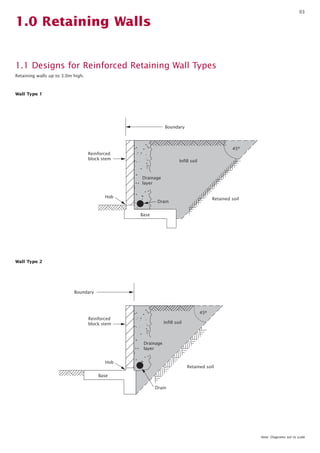
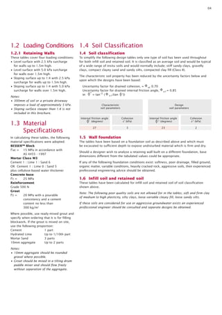
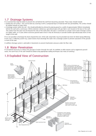
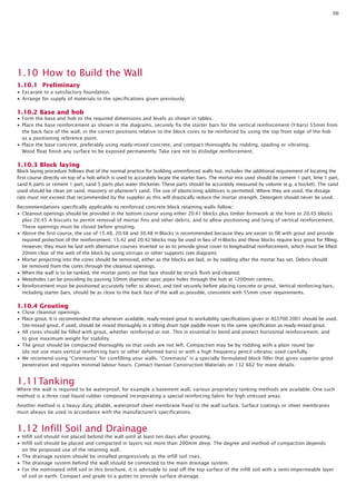
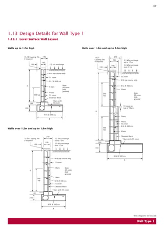
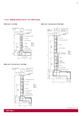
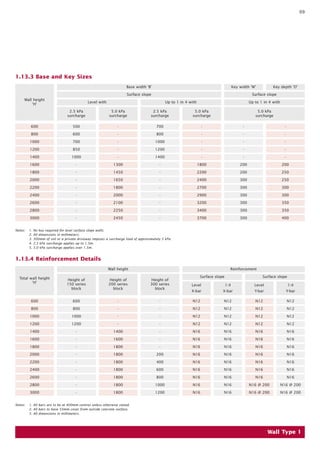
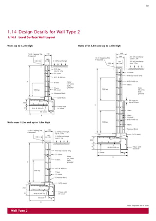
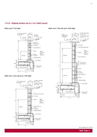
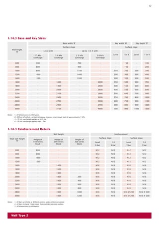
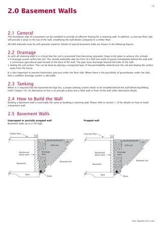
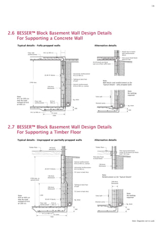
SlideShare a Scribd company logo
1 of 15
Download to read offline
How to build a Besser Block Wall
AUSTRALIAN PAVING CENTRE
Introduction
Preface 2
Introduction 2
1.0 Retaining walls 3
1.1 Designs for reinforced retaining
wall types 3
1.2 Loading Conditions 4
1.2.1 Retaining Walls 4
1.3 Material Specifications 4
1.4 Soil Classification 4
1.5 Wall Foundation 4
1.6 Infill Soil and Retained Soil 4
1.7 Drainage Systems 5
1.8 Water Penetration 5
1.9 Exploded View of Construction 5
1.10 How to Build the Wall 6
1.10.1 Preliminary 6
1.10.2 Base and Hob 6
1.10.3 Block Laying 6
1.10.4 Grouting 6
1.11 Tanking 6
1.12 Infill Soil and Drainage 6
1.13 Design Details for Wall Type 1 7
1.13.1 Level Surface Wall Layout 7
1.13.2 Sloping Surface up to 1 in 4
Wall Layout 8
1.13.3 Base and Key Sizes 9
1.13.4 Reinforcement Details 9
1.14 Design Details for Wall Type 2 10
1.14.1 Level Surface Wall Layout 10
1.14.2 Sloping Surface up to 1 in 4
Wall Layout 11
1.14.3 Base and Key Sizes 12
1.14.4 Reinforcement Details 12
2.0 Basement Walls 13
2.1 General 13
2.2 Drainage 13
2.3 Tanking 13
2.4 How to build the wall 13
2.5 Designs for reinforced basement
wall types 13
2.6 Besser block basement wall
design details for supporting
a concrete floor 14
2.7 Besser block basement wall
design details for supporting
a timber floor 14
2.8 Basement walls 15
Glossary 15
Contents
Preface
The designs shown in the brochure are based
on limit state design in accordance with the
provisions of AS4678-2002 Earth retaining
structures standard including Amendment
1, 2003. The designs are hereby certified by
Adbri Masonry Building Products Pty Ltd ABN
31 009 687 521.
The design details provided in this brochure
have been prepared by Adbri Masonry specifically
for Adbri Masonry blocks and are applicable
only to retaining walls using Adbri Masonry
products for residential or light commercial
applications up to 3.0m high. For higher and/or
more complex applications it is recommended
reference be made to the Concrete Masonry
Association of Australia document Reinforced
Concrete Masonry Cantilever Retaining Walls –
Design and Construction Guide MA51,
Amended July 2003.
Reinforced BESSER™ Block
Retaining and Basement
Walls consist of a reinforced
concrete base which anchors
the wall against overturning
and sliding, and a stem
of BESSER™ blocks.
The stem is reinforced with
steel bars placed vertically
and horizontally, and all cores
in the blocks are filled with
semi-fluid concrete, known as
‘grout’. The vertical reinforcing
bars in the cores are lapped
with shorter ‘starter bars’
embedded firmly in the
reinforced concrete base
using a hob to correctly
locate the bars. These short
bars allow easier block laying,
and the longer bars are put in
after all blocks are laid and
before grouting. The length of
the lap is critically important
and must be shown on the
drawings.
1.0 Retaining Walls
1.1 Designs for Reinforced Retaining Wall Types
Retaining walls up to 3.0m high.
03
Boundary
Retained soil
Base
Drain
Drainage
layer
Infill soil
Hob
Reinforced
block stem
45º
Boundary
Retained soil
Base
Drain
Drainage
layer
Infill soil
Hob
Reinforced
block stem
45º
Wall Type 1
Wall Type 2
Note: Diagrams not to scale
1.2 Loading Conditions
1.2.1 Retaining Walls
These tables cover four loading conditions:
• Level surface with 2.5 kPa surcharge
for walls up to 1.5m high.
• Level surface with 5.0 kPa surcharge
for walls over 1.5m high.
• Sloping surface up to 1:4 with 2.5 kPa
surcharge for walls up to 1.5m high.
• Sloping surface up to 1:4 with 5.0 kPa
surcharge for walls over 1.5m high.
Notes:
• 300mm of soil or a private driveway
imposes a load of approximately 5 kPa.
• Sloping surface steeper than 1:4 is not
included in this brochure.
1.3 Material
Specifications
In calculating these tables, the following
material specifications were adopted:
BESSER™ Block
f’uc = 15 MPa in accordance with
AS 4455 - 1997
Mortar Class M3
Cement 1 : Lime 1 : Sand 6
OR Cement 1 : Lime 0 : Sand 5
plus cellulose-based water thickener
Concrete base
f’c = 25 MPa
Reinforcement
Grade 500 N
Grout
f’c = 20 MPa with a pourable
consistency and a cement
content no less than
300 kg/m3
Where possible, use ready-mixed grout and
specify when ordering that it is for filling
blockwork. If the grout is mixed on site,
use the following proportion:
Cement 1 part
Hydrated Lime Up to 1/10th part
Mortar Sand 3 parts
10mm aggregate Up to 2 parts
Notes:
• 10mm aggregate should be rounded
gravel where possible.
• Grout should be mixed in a tilting drum
paddle mixer and should flow freely
without separation of the aggregate.
1.4 Soil Classification
1.4 Soil classification
To simplify the following design tables only one type of soil has been used throughout
for both infill soil and retained soil. It is classified as an average soil and would be typical
of a wide range of insitu soils and would normally include; stiff sandy clays, gravelly
clays, compact clayey sand and sandy silts, compacted clay fill (Class II).
The characteristic soil property has been reduced by the uncertainty factors below and
upon which the designs have been based:
Uncertainty factor for drained cohesion, = uc 0.70
Uncertainty factor for drained internal friction angle, u = 0.85
ie:
*
= tan-1 ( u (tan ‘))
1.5 Wall foundation
The tables have been based on a foundation soil as described above and which must
be excavated to sufficient depth to expose undisturbed material which is firm and dry.
Should a designer wish to analyse a retaining wall built on a different foundation, base
dimensions different from the tabulated values could be appropriate.
If any of the following foundation conditions exist: softness, poor drainage, filled ground,
organic matter, variable conditions, heavily cracked rock, aggressive soils, then experienced
professional engineering advice should be obtained.
1.6 Infill soil and retained soil
These tables have been calculated for infill soil and retained soil of soil classification
shown above.
Note: The following poor quality soils are not allowed for in the tables; soft and firm clay
of medium to high plasticity, silty clays, loose variable clayey fill, loose sandy silts.
If these soils are considered for use or aggressive groundwater exists an experienced
professional engineer should be consulted and separate designs be obtained.
Internal friction angle
‘ (degrees)
Cohesion
c’ (kPa)
Characteristic
soil parameters
27 3
Design
soil parameters
Internal friction angle
* (degrees)
Cohesion
c* (kPa)
23 2
04
05
Formwork to close cleanout
openings. Tie to vertical bars
with wire or support with
temporary timber struts.
Cleanout
Blocks 20.61
or 20.45
Position vertical X and
Y-bars to give 55mm
clear cover on earth side.
Cleanout
Biscuit 20.45A
Cleanout
Block 20.45
Wall base
Horizontal bars
in wall can be laid
on webs of H-blocks.
Blocks type
20.48
Grout all cores
Vertical X-bars
(Stem) lapped
with and tied to
starter Y-bars
Lap
Base longitudinal bars
Key
Vertical starter
Y-bars cast
into base
Grout
Hopper
Base transverse bars
Hob
Note:
Where 15.42 or 20.42 blocks are
in lieu of 20.48 blocks, lay alternative
courses inverted and support horizontal
reinforcement in the centre of the wall
and 20 mm clear of the webs.
Note: Diagrams not to scale
1.7 Drainage Systems
It is essential that steps be taken to prevent the soil behind the wall from becoming saturated. These steps should include:
• Sealing the soil surface – this can be done by covering it with a compacted layer of material with low permeability. The surface should
be sloped towards an open drain.
• A drainage system within the soil – this should preferably be achieved by placing gravel to a width of approximately 300mm immediately
behind the wall with a continuous 100mm diameter slotted pvc agricultural pipe with geo fabric sock located at the base of the wall.
The outlets from the pipe must be beyond the ends of the wall unless the pipe is connected to a proper storm water drainage system.
For higher walls, or in cases where excessive ground water exists it may be necessary to provide another agricultural pipe drain at mid
height of the wall.
If it is not possible to discharge the drains beyond the end of the wall, weep-holes may be provided (see items for block laying following).
In this case, a collecting system (e.g. spoon drains) must discharge the water into a drainage system to prevent saturation of the ground
in front of the wall.
A subfloor drainage system is advisable in basements to prevent hydrostatic pressure under the floor slab.
1.8 Water Penetration
If considered necessary to reduce the passage of water through the wall, for aesthetic or other reasons such as aggressive ground
water, the earth face of the wall should be treated using appropriate sealing techniques (see notes on tanking.)
1.9 Exploded View of Construction
06
1.10 How to Build the Wall
1.10.1 Preliminary
• Excavate to a satisfactory foundation.
• Arrange for supply of materials to the specifications given previously.
1.10.2 Base and hob
• Form the base and hob to the required dimensions and levels as shown in tables.
• Place the base reinforcement as shown in the diagrams, securely fix the starter bars for the vertical reinforcement (Y-bars) 55mm from
the back face of the wall, in the correct positions relative to the block cores to be reinforced by using the top front edge of the hob
as a positioning reference point.
• Place the base concrete, preferably using ready-mixed concrete, and compact thoroughly by rodding, spading or vibrating.
Wood float finish any surface to be exposed permanently. Take care not to dislodge reinforcement.
1.10.3 Block laying
Block laying procedure follows that of the normal practice for building unreinforced walls but, includes the additional requirement of locating the
first course directly on top of a hob which is used to accurately locate the starter bars. The mortar mix used should be cement 1 part, lime 1 part,
sand 6 parts or cement 1 part, sand 5 parts plus water thickener. These parts should be accurately measured by volume (e.g. a bucket). The sand
used should be clean pit sand, masonry or plasterer’s sand. The use of plasticising additives is permitted. Where they are used, the dosage
rate must not exceed that recommended by the supplier as this will drastically reduce the mortar strength. Detergent should never be used.
Recommendations specifically applicable to reinforced concrete block retaining walls follow:
• Cleanout openings should be provided in the bottom course using either 20.61 blocks plus timber formwork at the front or 20.45 blocks
plus 20.45 A biscuits to permit removal of mortar fins and other debris, and to allow positioning and tying of vertical reinforcement.
These openings must be closed before grouting.
• Above the first course, the use of 15.48, 20.48 and 30.48 H-Blocks is recommended because they are easier to fill with grout and provide
required protection of the reinforcement. 15.42 and 20.42 blocks may be used in lieu of H-Blocks and these blocks require less grout for filling.
However, they must be laid with alternative courses inverted so as to provide grout cover to longitudinal reinforcement, which must be lifted
20mm clear of the web of the block by using stirrups or other supports (see diagram).
• Mortar projecting into the cores should be removed, either as the blocks are laid, or by rodding after the mortar has set. Debris should
be removed from the cores through the cleanout openings.
• When the wall is to be tanked, the mortar joints on that face should be struck flush and cleaned.
• Weepholes can be providing by passing 50mm diameter upvc pipes holes through the hob at 1200mm centres.
• Reinforcement must be positioned accurately (refer to above), and tied securely before placing concrete or grout. Vertical reinforcing bars,
including starter bars, should be as close to the back face of the wall as possible, consistent with 55mm cover requirements.
1.10.4 Grouting
• Close cleanout openings.
• Place grout. It is recommended that whenever available, ready-mixed grout to workability specifications given in AS3700 2001 should be used.
Site-mixed grout, if used, should be mixed thoroughly in a tilting drum type paddle mixer to the same specification as ready-mixed grout.
• All cores should be filled with grout, whether reinforced or not. This is essential to bond and protect horizontal reinforcement, and
to give maximum weight for stability.
• The grout should be compacted thoroughly so that voids are not left. Compaction may be by rodding with a plain round bar
(do not use main vertical reinforcing bars or other deformed bars) or with a high frequency pencil vibrator, used carefully.
• We recomend using “Coremasta” for corefilling your walls. “Coremasta” is a specially formulated block filler that gives superior grout
penetration and requires minimal labour hours. Contact Hanson Construction Materials on 132 662 for more details.
1.11Tanking
Where the wall is required to be waterproof, for example a basement wall, various proprietary tanking methods are available. One such
method is a three coat liquid rubber compound incorporating a special reinforcing fabric for high stressed areas.
Another method is a heavy duty, pliable, waterproof sheet membrane fixed to the wall surface. Surface coatings or sheet membranes
must always be used in accordance with the manufacturer’s specifications.
1.12 Infill Soil and Drainage
• Infill soil should not placed behind the wall until at least ten days after grouting.
• Infill soil should be placed and compacted in layers not more than 200mm deep. The degree and method of compaction depends
on the proposed use of the retaining wall.
• The drainage system should be installed progressively as the infill soil rises.
• The drainage system behind the wall should be connected to the main drainage system.
• For the nominated infill soil in this brochure, it is advisable to seal off the top surface of the infill soil with a semi-impermeable layer
of soil or earth. Compact and grade to a gutter to provide surface drainage.
07
1.13 Design Details for Wall Type 1
1.13.1 Level Surface Wall Layout
Wall Type 1
Note: Diagrams not to scale
75.10 Capping Tile
if required
100
190
140
2.5 kPa surcharge
N16 top course only
55 cover
N12 @ 400 crs
X-bars
Y-bars
Y-bars with
55 cover100
200
B
55 cover
N16 @ 300 crs
500 lap
Cleanout Block
H
10.31 Capping Tile
if required
100
H
700
lap
N16 top course only
55 cover
X-bars
N12 @ 400 crs
Y-bars
55 cover
Cleanout Block
Y-bars with 55 cover
100
250
B
N16 @ 300 crs
240
2.5 kPa surcharge
up to 1.5m
5.0 kPa surcharge
over 1.5m
190
10.31
Capping Tile
if required
100
340
2.5 kPa surcharge
up to 1.5m
5.0 kPa surcharge
over 1.5m
55 cover
N16 top course only
X-bars
N12 @ 400 crs
55 cover to
top of Y-bars
Y-bars
Y-bars
55 cover
N16 @ 400 crs
X-bars
Cleanout Block
Y-bars with 55 cover
N16 @ 300 crs
B
350
100
700
lap
700
lap
290
190
H
Walls up to 1.2m high Walls over 1.8m and up to 3.0m high
Walls over 1.2m and up to 1.8m high
Note:
All cores
fully
grouted
Note:
All cores
fully
grouted
Note:
All cores
fully
grouted
07
1.13.2 Sloping Surface up to 1 in 4 Wall Layout
Note: Diagrams not to scale
75.10 Capping Tile
if required
H
500
lap
N16 top course only
55 cover
X-bars
N12 @ 400 crs
Y-bars
55 cover
Cleanout Block
Y-bars with 55 cover
100
200
B
N16 @ 300 crs
190
2.5 kPa surcharge
140
100
10.31 Capping Tile
if required
H
700
lap
N16 top course only
55 cover
X-bars
N12 @ 400 crs
Y-bars
55 cover
Cleanout Block
Y-bars with 55 cover
100
250
B
W
D N16 @ 300 crs
240
2.5 kPa surcharge
up to 1.5m
5.0 kPa surcharge
over 1.5m190
100
10.31
Capping Tile
if required
100
340
2.5 kPa surcharge
up to 1.5m
5.0 kPa surcharge
over 1.5m
55 cover
N16 top course only
X-bars
N12 @ 400 crs
55 cover to
top of Y-bars
Y-bars
Y-bars
55 cover
N16 @ 400 crs
X-bars
Cleanout Block
Y-bars with 55 cover
N16 @ 300 crs
W
B
D
350
100
700
lap
700
lap
290
190
H
Walls up to 1.2m high Walls over 1.8m and up to 3.0m high
Walls over 1.2m and up to 1.8m high
Wall Type 1
Note:
All cores
fully
grouted
Note:
All cores
fully
grouted
Note:
All cores
fully
grouted
09
600
800
1000
1200
Wall height
‘H’
1400
1600
1800
2000
2200
2400
500
600
700
850
Base width ‘B’
Surface slope
1000
-
-
-
-
-
Key width ‘W’ Key depth ‘D’
Surface slope
Level with Up to 1 in 4 with Up to 1 in 4 with
2.5 kPa
surcharge
5.0 kPa
surcharge
2.5 kPa
surcharge
5.0 kPa
surcharge
5.0 kPa
surcharge
2600 -
2800 -
3000 -
-
-
-
-
-
1300
1450
1650
1800
2000
700
800
1000
1200
1400
-
-
-
-
-
2100 -
2250 -
2450 -
-
-
-
-
-
1800
2200
2400
2700
2900
-
-
-
-
-
200
200
300
300
300
3200 300
3400 300
3700
-
-
-
-
-
200
250
250
300
300
350
350
400300
1.13.3 Base and Key Sizes
600
800
1000
1200
Total wall height
‘H’
1400
1600
1800
2000
2200
2400
600
800
1000
1200
Wall height Reinforcement
-
-
-
-
-
-
Surface slope Surface slope
Height of
150 series
block
Height of
200 series
block
Height of
300 series
block
Level
X-bar
2600 -
2800 -
3000 -
-
-
-
-
1400
1600
1800
1800
1800
1800
-
-
-
-
-
-
-
200
400
600
1800 800
1800 1000
1800 1200
N12
N12
N12
N12
N16
N16
N16
N16
N16
N16
N16
N16
N16
1:4
X-bar
N12
N12
N12
N12
N16
N16
N16
N16
N16
N16
N16
N16
N16
Level
Y-bar
N12
N12
N12
N12
N16
N16
N16
N16
N16
N16
N16
N16 @ 200
N16 @ 200
1:4
Y-bar
N12
N12
N12
N12
N16
N16
N16
N16
N16
N16
N16
N16 @ 200
N16 @ 200
1.13.4 Reinforcement Details
Wall Type 1
Notes: 1. No key required for level surface slope walls.
2. All dimensions in millimeters.
3. 300mm of soil or a private driveway imposes a surcharge load of approximately 5 kPa.
4. 2.5 kPa surcharge applies up to 1.5m.
5. 5.0 kPa surcharge applies over 1.5m.
Notes: 1. All bars are to be at 400mm centres unless otherwise stated.
2. All bars to have 55mm cover from outside concrete surface.
3. All dimensions in millimeters.
10
1.14 Design Details for Wall Type 2
1.14.1 Level Surface Wall Layout
Note: Diagrams not to scale
75.10 Capping Tile
if required
100
190
140
2.5 kPa surcharge
N16 top
course only
55 cover
N12 @ 400 crs
X-bars
Y-bars
Y-bars with
55 cover
SL72 Mesh100
200
D
B
W
55 cover
55 cover
N16 @ 300 crs
500 lap
Cleanout Block
H
10.31 Capping Tile
if required
100
H
700 lap
N16 top course only
55 cover
X-bars
N12 @ 400 crs
Y-bars
55 cover
Cleanout Block
SL72 mesh
Y-bars with
55 cover
100
250
D
B
55 cover
N16 @ 300 crs
W
240
2.5 kPa surcharge
up to 1.5m
5.0 kPa surcharge
over 1.5m
190
10.31 Capping Tile
if required
100
340
2.5 kPa surcharge
up to 1.5m
5.0 kPa surcharge
over 1.5m
290
190
55 cover
N16 top course only
N12 @ 400 crs
55 cover to
top of Y-bars
Y-bars
Y-bars
Y-bars with
55 cover
W
B
55 cover
N16 @ 300 crs
100
350
D
55 cover
N16 @ 400 crs
X-bars
Cleanout Block
SL72 mesh
X-bars
700 lap
700 lap
H
Walls up to 1.2m high Walls over 1.8m and up to 3.0m high
Walls over 1.2m and up to 1.8m high
Wall Type 2
Note:
All cores
fully
grouted
Note:
All cores
fully
grouted
Note:
All cores
fully
grouted
11
1.14.2 Sloping Surface up to 1 in 4 Wall Layout
Note: Diagrams not to scale
75.10 Capping Tile
if required
100
190
140
2.5 kPa
surcharge
N16 top
course only
55 cover
N12 @ 400 crs
X-bars
Y-bars
Y-bars with
55 cover
SL72 Mesh100
200
D
B
W
55 cover
55 cover
N16 @ 300 crs
500 lap
Cleanout Block
H
10.31 Capping Tile
if required
100
H
700 lap
N16 top course only
55 cover
X-bars
N12 @ 400 crs
Y-bars
55 cover
Cleanout Block
SL72 mesh
Y-bars with
55 cover
100
250
D
B
55 cover
N16 @ 300 crs
W
240 2.5 kPa surcharge
up to 1.5m
5.0 kPa surcharge
over 1.5m190
10.31
Capping Tile
if required
100
340 2.5 kPa surcharge
up to 1.5m
5.0 kPa surcharge
over 1.5m
55 cover
N16 top course only
X-bars
N12 @ 400 crs
55 cover to
top of Y-bars
Y-bars
Y-bars
55 cover
55 cover
N16 @ 400 crs
X-bars
Cleanout Block
Y-bars with
55 cover
SL72 mesh
N16 @ 300 crs
W
B
D
350
100
700 lap
700 lap
290
190
H
Walls up to 1.2m high Walls over 1.8m and up to 3.0m high
Walls over 1.2m and up to 1.8m high
Wall Type 2
Note:
All cores
fully
grouted
Note:
All cores
fully
grouted
Note:
All cores
fully
grouted
12
600
800
1000
1200
Wall height
‘H’
1400
1600
1800
2000
2200
2400
500
800
800
1000
Base width ‘B’
Surface slope
1100
-
-
-
-
-
Key width ‘W’ Key depth ‘D’
Surface slope
Level with Up to 1 in 4 with
Level 1 in 4 Level 1 in 42.5 kPa
surcharge
5.0 kPa
surcharge
2.5 kPa
surcharge
5.0 kPa
surcharge
2600 -
2800 -
3000 -
-
-
-
-
-
1600
1900
2000
2200
2400
700
900
1100
1400
1500
-
-
-
-
-
2700 -
2900 -
3100 -
-
-
-
-
-
2200
2400
2600
2900
3200
-
-
150
200
200
350
400
400
500
550
3500 600
3700 600
4000
150
150
200
300
350
500
550
550
600
700
750
800
900700
-
-
200
300
300
500
600
600
700
800
900
900
100
200
300
400
500
700
800
800
900
1000
1100
1200
13001000
1.14.3 Base and Key Sizes
600
800
1000
1200
Total wall height
‘H’
1400
1600
1800
2000
2200
2400
600
800
1000
1200
Wall height Reinforcement
-
-
-
-
-
-
Surface slope Surface slope
Height of
150 series
block
Height of
200 series
block
Height of
300 series
block
Level
X-bar
2600 -
2800 -
3000 -
-
-
-
-
1400
1600
1800
1800
1800
1800
-
-
-
-
-
-
-
200
400
600
1800 800
1800 1000
1800 1200
N12
N12
N12
N12
N16
N16
N16
N16
N16
N16
N16
N16
N16
1:4
X-bar
N12
N12
N12
N12
N16
N16
N16
N16
N16
N16
N16
N16
N16
Level
Y-bar
N12
N12
N12
N12
N16
N16
N16
N16
N16
N16
N16
N16 @ 200
N16 @ 200
1:4
Y-bar
N12
N12
N12
N12
N16
N16
N16
N16
N16
N16
N16
N16 @ 200
N16 @ 200
1.14.3 Reinforcement Details
Wall Type 2
Notes: 1. All dimensions in millimeters.
2. 300mm of soil or a private driveway imposes a surcharge load of approximately 5 kPa.
3. 2.5 kPa surcharge applies up to 1.5m.
4. 5.0 kPa surcharge applies over 1.5m.
Notes: 1. All bars are to be at 400mm centres unless otherwise stated.
2. All bars to have 55mm cover from outside concrete surface.
3. All dimensions in millimeters.
13
2.0 Basement Walls
2.1 General
The foundation slab of a basement can be modified to provide an efficient footing for a retaining wall. In addition, a concrete floor slab
will provide a ‘prop’ to the top of the wall, simplifying the wall details compared to a timber floor.
All infill materials must be with granular material. Details of typical basement walls are shown in the following figures.
2.2 Drainage
As with all retaining walls it is critical that the soil is prevented from becoming saturated. Steps to be taken to achieve this include:
• A drainage system within the soil. This should preferably take the form of a 300 mm width of gravel immediately behind the wall with
a continuous agricultural pipe located at the base of the wall. The pipe must discharge beyond the ends of the wall.
• Sealing the soil surface. This can be done by placing a compacted layer of low-permeability material over the soil and sloping the surface
away from the house.
It is also important to prevent hydrostatic pressure under the floor slab. Where there is the possibility of groundwater under the slab,
then a subfloor drainage system is advisable.
2.3 Tanking
Where it is required that the basement be kept dry, a proper tanking system needs to be installed behind the wall before backfilling
(refer Chapter 10). An alternative to this is to provide a drain and a false wall in front of the wall (refer alternative detail).
2.4 How to Build the Wall
Building a Basement wall is essentially the same as building a retaining wall. Please refer to section 1.10 for details on how to build
a basement wall.
2.5 Basement Walls
Basement
Retained soil
Base
Drain
Drainage
layer
Infill soil
Timber floor
Reinforced
block stem
45º
Basement
Retained soil
Base
Drain
Drainage
layer
Infill soil
Concrete floor
Reinforced
block stem
45º
Unpropped or partially propped wall
Basement walls up to 2.7m high.
Propped wall
Note: Diagrams not to scale
14
2.6 BESSER™ Block Basement Wall Design Details
For Supporting a Concrete Wall
Floor slab
reinforcement
N12 at 200 crs
False wall
Drained cavity
Note:
N12 at 200 crs
may be used
instead of N16
at 400 crs
Note:
No tanking
required
Starter bar to match
wall reinforcement
above
One-course bond beam
with N12 bar
Note:
Wall blocks and reinforcement as for
‘Typical Details’ - fully propped walls
20.48 ‘H’ blocks
Vertical reinforcement
N16 at 400 crs, central
Horizontal reinforcement
N12 at 400 crs
20.20 knock-out block
saw-cut at floor soffit level
Tanking to back face
of wall
Ag. drain
Ag. drain
190 thick
blockwork
N16 at
400 crs
N12 at 400 crs
55 cover
200
200
1000
2700 max.
Floor slab
reinforcement
Timber floor Timber floor140-thick
blockwork
190-thick
blockwork
False wall
Drained cavity
Note:
N20 at 400 crs
may be used
instead of N16
at 200 crs
Note:
No tanking
required
Pole plate fixed
to bond beam
One-course bond beam
using 20.20 knock-out block
with 1-N12 bar
Note:
Reinforcement as for ‘Typical Details’
290-thick
blockwork
20.48 ‘H’ blocks
Vertical reinforcement
N16 at 400 crs, central
Horizontal reinforcement
N12 at 400 crs
55 cover to back face
Tanking to back face
of wall
55 cover to back face
Ag. drain
Ag. drain
190 thick
blockwork
290 thick
blockwork
30.48 ‘H’ blocks
Floor slab
reinforcement
N16 at
200 crs
N12 at 400 crs
55 cover
300 300
1500
2700 max. to
ground level
1200
Note: Diagrams not to scale
Typical details - Fully-propped walls
Typical details - Unpropped or partially-propped walls
Alternative details
Alternative details
2.7 BESSER™ Block Basement Wall Design Details
For Supporting a Timber Floor
2.8 Basement Walls
These designs are based on a level surface
with 5 kPa surcharge. Walls designed as propped
must not be backfilled before the concrete
floor at the top of the wall is in place.
Important Notes
No loadings should be applied (e.g. from footings),
within the area of infill soil other than those
loadings referred to above.
The area of infill soil is bounded by a line at 45°
to the rear of the base as illustrated in chapter 1.
Only one typical soil case is presented.
These tables may not provide an ideal solution
in a particular case.
For situations other than those covered by the
tables, or if there is doubt as to:
• The strength and stability of the foundation
material the drainage system needed
• An experienced professional engineer should
be consulted for advice.
Load and Limit States:
Dead load*
The self-weight of the structure, infill soil, retained soil or rock.
Live load*
Loads that arise from the intended use of the structure, including
distributed, concentrated, impact and inertia loads. It includes
construction loads, but excludes wind and earthquake loads.
Surcharge
A uniformaly distributed external load. For retaining walls under 1.5m
a minimum load of 2.5 kPa. For retaining walls over 1.5m a minimum
load of 5 kPa.
Stability limit state
A limit state of loss of static equilibrium of a structure or part thereof,
when considered as a rigid body.
Strength limit state
A limit state of collapse or loss of structural integrity of the components
of the retaining wall.
Serviceability limit state
A limit state for acceptable in-service conditions. The most common
serviceability states are excessive differential settlement and forward
movement of the retaining wall.
Components:
Concrete masonry units
Concrete blocks manufactured to provide an attractive, durable, stable
face to a retaining wall. The recommended block types are the 15.48,
20.48 and 30.48 ‘H’ blocks.
Retained soil
The natural soil, intended to be retained by a retaining wall.
Foundation soil
The natural soil material under a retaining wall.
Infill soil
The soil material placed behind the retaining wall facing. Often retained
soil is used for this purpose.
* This brochure uses the terminology ‘dead load’ to indicate permanent
loads and ‘live load’ to indicate imposed loads. This terminology is
consistent with the convention adopted in AS 4678-2002.
Glossary
Flinders Park
284 Grange Road, Flinders Park, SA 5025
phone: (08) 8234 7144 I fax: (08) 8234 9644
Gawler
Cnr Main North & Tiver Rd, Evanston, SA 5116
phone: (08) 8522 2522 I fax: (08) 8522 2488
Gepps Cross
700 Main North Road, Gepps Cross, SA 5094
phone: (08) 8349 5311 I fax: (08) 8349 5833
Holden Hill
578 North East Road, Holden Hill, SA 5088
phone: (08) 8369 0200 I fax: (08) 8266 6855
Kadina
86 Port Road, Kadina, SA 5554
phone: (08) 8821 2077 | fax: (08) 8821 2977
Lonsdale
13 Sherriffs Road, Lonsdale, SA 5160
phone: (08) 8381 2400 I fax: (08) 8381 2366
Mount Barker
Westbourne Park
4 Oborn Road, Mount Barker, SA 5251
455 Goodwood Rd, Westbourne Park, SA 5041
phone: (08) 8391 3467 fax: (08) 8398 2518
phone: (08) 8299 9633 I fax: 08) 8299 9688
Mount Gambier
Whyalla
6 Graham Road, Mount Gambier West, SA 5291
132 Norrie Ave, Whyalla Norrie, SA 5608
phone: (08) 8725 6019 I fax: (08) 8725 3724
phone: (08) 8644 0918 I mob: 0412 810 056
Hallet Cove
9-11 Commercial Road, Sheidow Park, SA 5158
phone: (08) 8381 9142 I fax: (08) 8381 7666
Streaky Bay
18 Bay Road, Streaky Bay, SA 5680
phone: (08) 8626 7011 I mob: 0427 263 050

More Related Content

What's hot

Pile cap two pile laod 50 t desigh and drawing
Pile cap  two pile laod 50 t  desigh and drawingPile cap  two pile laod 50 t  desigh and drawing
Pile cap two pile laod 50 t desigh and drawingRAJESH JAIN
 
Civil engineering - thumb rule
Civil engineering - thumb ruleCivil engineering - thumb rule
Civil engineering - thumb ruleBenAdem1
 
KINH NGHIÊM BỐ TRÍ LÕI VÁCH THANG MÁY
KINH NGHIÊM BỐ TRÍ LÕI VÁCH THANG MÁYKINH NGHIÊM BỐ TRÍ LÕI VÁCH THANG MÁY
KINH NGHIÊM BỐ TRÍ LÕI VÁCH THANG MÁYVOBAOTOAN
 
Punching Shears 1.1
Punching Shears 1.1Punching Shears 1.1
Punching Shears 1.1Milan Stanic
 
Post tensioned (PT) slabs
Post tensioned (PT) slabsPost tensioned (PT) slabs
Post tensioned (PT) slabsFOYSOLMAHMUD1
 
Finishing works detail of residence building
Finishing works detail of residence buildingFinishing works detail of residence building
Finishing works detail of residence buildingshamal das
 
Advantages, Disadvantages and Uses of Lightweight Concrete
Advantages, Disadvantages and Uses of Lightweight ConcreteAdvantages, Disadvantages and Uses of Lightweight Concrete
Advantages, Disadvantages and Uses of Lightweight ConcreteShyam Steel TMT Bar
 
GROUP PROJECT: PROPOSAL FOR THE FINISHED/ EXISTING BUILDING CONSTRUCTION (CAS...
GROUP PROJECT: PROPOSAL FOR THE FINISHED/ EXISTING BUILDING CONSTRUCTION (CAS...GROUP PROJECT: PROPOSAL FOR THE FINISHED/ EXISTING BUILDING CONSTRUCTION (CAS...
GROUP PROJECT: PROPOSAL FOR THE FINISHED/ EXISTING BUILDING CONSTRUCTION (CAS...Firdaurs Abdullah
 
Chương 3 cầu thang
Chương 3 cầu thangChương 3 cầu thang
Chương 3 cầu thangVương Hữu
 
AAC Installation Guidelines
AAC Installation GuidelinesAAC Installation Guidelines
AAC Installation GuidelinesBENAY MUNDA
 
post tensioning slabs
post tensioning slabspost tensioning slabs
post tensioning slabsgopichand's
 
03.Hệ số nền và sức chịu tải của nền
03.Hệ số nền và sức chịu tải của nền 03.Hệ số nền và sức chịu tải của nền
03.Hệ số nền và sức chịu tải của nền Education Vietcivil
 
PRECAST BUILDING SYSTEM
PRECAST BUILDING SYSTEMPRECAST BUILDING SYSTEM
PRECAST BUILDING SYSTEMSagar Shah
 
Các Loại Móng Và 9 Bí Mật Gia Chủ Không Biết Khi Thi Công Móng
Các Loại Móng Và 9 Bí Mật Gia Chủ Không Biết Khi Thi Công MóngCác Loại Móng Và 9 Bí Mật Gia Chủ Không Biết Khi Thi Công Móng
Các Loại Móng Và 9 Bí Mật Gia Chủ Không Biết Khi Thi Công MóngKiến Trúc KISATO
 

What's hot (20)

Raft foundations 1
Raft foundations 1Raft foundations 1
Raft foundations 1
 
Đề tài: Nghiên cứu áp dụng cọc Barrette được gia cường, HAY
Đề tài: Nghiên cứu áp dụng cọc Barrette được gia cường, HAYĐề tài: Nghiên cứu áp dụng cọc Barrette được gia cường, HAY
Đề tài: Nghiên cứu áp dụng cọc Barrette được gia cường, HAY
 
Pile cap two pile laod 50 t desigh and drawing
Pile cap  two pile laod 50 t  desigh and drawingPile cap  two pile laod 50 t  desigh and drawing
Pile cap two pile laod 50 t desigh and drawing
 
Deep excavations
Deep excavationsDeep excavations
Deep excavations
 
Civil engineering - thumb rule
Civil engineering - thumb ruleCivil engineering - thumb rule
Civil engineering - thumb rule
 
KINH NGHIÊM BỐ TRÍ LÕI VÁCH THANG MÁY
KINH NGHIÊM BỐ TRÍ LÕI VÁCH THANG MÁYKINH NGHIÊM BỐ TRÍ LÕI VÁCH THANG MÁY
KINH NGHIÊM BỐ TRÍ LÕI VÁCH THANG MÁY
 
Punching Shears 1.1
Punching Shears 1.1Punching Shears 1.1
Punching Shears 1.1
 
Post tensioned (PT) slabs
Post tensioned (PT) slabsPost tensioned (PT) slabs
Post tensioned (PT) slabs
 
Finishing works detail of residence building
Finishing works detail of residence buildingFinishing works detail of residence building
Finishing works detail of residence building
 
FINISHING WORKS- MASONRY.pptx
FINISHING WORKS- MASONRY.pptxFINISHING WORKS- MASONRY.pptx
FINISHING WORKS- MASONRY.pptx
 
Advantages, Disadvantages and Uses of Lightweight Concrete
Advantages, Disadvantages and Uses of Lightweight ConcreteAdvantages, Disadvantages and Uses of Lightweight Concrete
Advantages, Disadvantages and Uses of Lightweight Concrete
 
GROUP PROJECT: PROPOSAL FOR THE FINISHED/ EXISTING BUILDING CONSTRUCTION (CAS...
GROUP PROJECT: PROPOSAL FOR THE FINISHED/ EXISTING BUILDING CONSTRUCTION (CAS...GROUP PROJECT: PROPOSAL FOR THE FINISHED/ EXISTING BUILDING CONSTRUCTION (CAS...
GROUP PROJECT: PROPOSAL FOR THE FINISHED/ EXISTING BUILDING CONSTRUCTION (CAS...
 
Stepped footing
Stepped footingStepped footing
Stepped footing
 
Chương 3 cầu thang
Chương 3 cầu thangChương 3 cầu thang
Chương 3 cầu thang
 
AAC Installation Guidelines
AAC Installation GuidelinesAAC Installation Guidelines
AAC Installation Guidelines
 
post tensioning slabs
post tensioning slabspost tensioning slabs
post tensioning slabs
 
03.Hệ số nền và sức chịu tải của nền
03.Hệ số nền và sức chịu tải của nền 03.Hệ số nền và sức chịu tải của nền
03.Hệ số nền và sức chịu tải của nền
 
PRECAST BUILDING SYSTEM
PRECAST BUILDING SYSTEMPRECAST BUILDING SYSTEM
PRECAST BUILDING SYSTEM
 
Deep foundation - pile foundation
Deep foundation - pile foundationDeep foundation - pile foundation
Deep foundation - pile foundation
 
Các Loại Móng Và 9 Bí Mật Gia Chủ Không Biết Khi Thi Công Móng
Các Loại Móng Và 9 Bí Mật Gia Chủ Không Biết Khi Thi Công MóngCác Loại Móng Và 9 Bí Mật Gia Chủ Không Biết Khi Thi Công Móng
Các Loại Móng Và 9 Bí Mật Gia Chủ Không Biết Khi Thi Công Móng
 

Similar to How to Build Besser Block Retaining Walls

Btech compile 6 oct 4am
Btech compile 6 oct 4amBtech compile 6 oct 4am
Btech compile 6 oct 4amCeline Tan
 
Allan block Commercial brochure
Allan block Commercial brochureAllan block Commercial brochure
Allan block Commercial brochurekristenjames
 
Versaloc - very easy, very quick
Versaloc - very easy, very quickVersaloc - very easy, very quick
Versaloc - very easy, very quickkristenjames
 
Soldier Bored and Diaphragm
Soldier Bored and DiaphragmSoldier Bored and Diaphragm
Soldier Bored and DiaphragmYingHongKang
 
Chapter 5 formwork
Chapter 5 formworkChapter 5 formwork
Chapter 5 formworkKHUSHBU SHAH
 
EXCAVATION FOR FOUNDATION - Methods & Temporary Earth Retaining Structures
EXCAVATION FOR FOUNDATION - Methods & Temporary Earth Retaining StructuresEXCAVATION FOR FOUNDATION - Methods & Temporary Earth Retaining Structures
EXCAVATION FOR FOUNDATION - Methods & Temporary Earth Retaining StructuresShivananda Roy
 
Allan block Installation guide
Allan block Installation guideAllan block Installation guide
Allan block Installation guidekristenjames
 
Specifications of rcc foundation
Specifications of rcc foundation Specifications of rcc foundation
Specifications of rcc foundation Prabhat chhirolya
 
6. FORMWORK (ACE) 2160601 GTU
6. FORMWORK (ACE) 2160601 GTU6. FORMWORK (ACE) 2160601 GTU
6. FORMWORK (ACE) 2160601 GTUVATSAL PATEL
 
Lesson 3 Floor screeds _suspended floors.pptx
Lesson 3 Floor screeds _suspended floors.pptxLesson 3 Floor screeds _suspended floors.pptx
Lesson 3 Floor screeds _suspended floors.pptxsydneyaugust1
 
Secant piled walls dsign - تصميم خوازيق الجدران الساندة - ميكرو بايل
Secant piled walls  dsign - تصميم خوازيق الجدران الساندة - ميكرو بايلSecant piled walls  dsign - تصميم خوازيق الجدران الساندة - ميكرو بايل
Secant piled walls dsign - تصميم خوازيق الجدران الساندة - ميكرو بايلDr.youssef hamida
 

Similar to How to Build Besser Block Retaining Walls (20)

Versaloc (1)
Versaloc (1)Versaloc (1)
Versaloc (1)
 
Versaloc (1)
Versaloc (1)Versaloc (1)
Versaloc (1)
 
Btech compile 6 oct 4am
Btech compile 6 oct 4amBtech compile 6 oct 4am
Btech compile 6 oct 4am
 
Allan block Commercial brochure
Allan block Commercial brochureAllan block Commercial brochure
Allan block Commercial brochure
 
Versaloc - very easy, very quick
Versaloc - very easy, very quickVersaloc - very easy, very quick
Versaloc - very easy, very quick
 
Interlocking pavement
Interlocking pavementInterlocking pavement
Interlocking pavement
 
Soldier Bored and Diaphragm
Soldier Bored and DiaphragmSoldier Bored and Diaphragm
Soldier Bored and Diaphragm
 
Chapter 5 formwork
Chapter 5 formworkChapter 5 formwork
Chapter 5 formwork
 
IS 13827
IS 13827IS 13827
IS 13827
 
EXCAVATION FOR FOUNDATION - Methods & Temporary Earth Retaining Structures
EXCAVATION FOR FOUNDATION - Methods & Temporary Earth Retaining StructuresEXCAVATION FOR FOUNDATION - Methods & Temporary Earth Retaining Structures
EXCAVATION FOR FOUNDATION - Methods & Temporary Earth Retaining Structures
 
Allan block Installation guide
Allan block Installation guideAllan block Installation guide
Allan block Installation guide
 
Specifications of rcc foundation
Specifications of rcc foundation Specifications of rcc foundation
Specifications of rcc foundation
 
Pile foundation
Pile foundation Pile foundation
Pile foundation
 
6. FORMWORK (ACE) 2160601 GTU
6. FORMWORK (ACE) 2160601 GTU6. FORMWORK (ACE) 2160601 GTU
6. FORMWORK (ACE) 2160601 GTU
 
Lesson 3 Floor screeds _suspended floors.pptx
Lesson 3 Floor screeds _suspended floors.pptxLesson 3 Floor screeds _suspended floors.pptx
Lesson 3 Floor screeds _suspended floors.pptx
 
Top Down Construction Presentation.
Top Down Construction Presentation.Top Down Construction Presentation.
Top Down Construction Presentation.
 
Secant piled walls dsign - تصميم خوازيق الجدران الساندة - ميكرو بايل
Secant piled walls  dsign - تصميم خوازيق الجدران الساندة - ميكرو بايلSecant piled walls  dsign - تصميم خوازيق الجدران الساندة - ميكرو بايل
Secant piled walls dsign - تصميم خوازيق الجدران الساندة - ميكرو بايل
 
pile wall
pile wallpile wall
pile wall
 
IS 13828
IS 13828IS 13828
IS 13828
 
Retaining walls
Retaining walls Retaining walls
Retaining walls
 

More from kristenjames

Yin and sound Immersion
Yin and sound ImmersionYin and sound Immersion
Yin and sound Immersionkristenjames
 
Melbourne boat hire proposal cruises
Melbourne boat hire proposal cruisesMelbourne boat hire proposal cruises
Melbourne boat hire proposal cruiseskristenjames
 
Residential Energy Audits
Residential Energy AuditsResidential Energy Audits
Residential Energy Auditskristenjames
 
Melbourne boat hire birrarung
Melbourne boat hire birrarungMelbourne boat hire birrarung
Melbourne boat hire birrarungkristenjames
 
Melbourne boat-hire-brochure-august-2018 (1)
Melbourne boat-hire-brochure-august-2018 (1)Melbourne boat-hire-brochure-august-2018 (1)
Melbourne boat-hire-brochure-august-2018 (1)kristenjames
 
Melbourne boat hire photography cruise flyer
Melbourne boat hire photography cruise flyerMelbourne boat hire photography cruise flyer
Melbourne boat hire photography cruise flyerkristenjames
 
HOW TO SET VIDEO ALARMS ON THE CONNECT APP
HOW TO SET VIDEO ALARMS ON THE CONNECT APPHOW TO SET VIDEO ALARMS ON THE CONNECT APP
HOW TO SET VIDEO ALARMS ON THE CONNECT APPkristenjames
 
The Present - Yoga Teacher Training
The	Present - Yoga Teacher TrainingThe	Present - Yoga Teacher Training
The Present - Yoga Teacher Trainingkristenjames
 
Yarra River Skippered Cruises and Private Boat Charter
Yarra River Skippered Cruises and Private Boat CharterYarra River Skippered Cruises and Private Boat Charter
Yarra River Skippered Cruises and Private Boat Charterkristenjames
 
Sound immersion on 22nd-December 2019 at UpDog Yoga
Sound immersion on 22nd-December 2019 at UpDog YogaSound immersion on 22nd-December 2019 at UpDog Yoga
Sound immersion on 22nd-December 2019 at UpDog Yogakristenjames
 
Vinyasa unlocked - UpDog Yoga
Vinyasa unlocked - UpDog YogaVinyasa unlocked - UpDog Yoga
Vinyasa unlocked - UpDog Yogakristenjames
 
Movement as medicine - UpDog Yoga
Movement as medicine - UpDog YogaMovement as medicine - UpDog Yoga
Movement as medicine - UpDog Yogakristenjames
 
Yoga studios melbourne updog yoga
Yoga studios melbourne  updog yogaYoga studios melbourne  updog yoga
Yoga studios melbourne updog yogakristenjames
 
Melbourne boat-hire-photography-cruise-flyer
Melbourne boat-hire-photography-cruise-flyerMelbourne boat-hire-photography-cruise-flyer
Melbourne boat-hire-photography-cruise-flyerkristenjames
 
Erectarack long span shelving-3
Erectarack long span shelving-3Erectarack long span shelving-3
Erectarack long span shelving-3kristenjames
 
Erectarack Raised Storage Areas
Erectarack Raised Storage Areas Erectarack Raised Storage Areas
Erectarack Raised Storage Areas kristenjames
 
Erectarack mezzanine Floor
Erectarack mezzanine FloorErectarack mezzanine Floor
Erectarack mezzanine Floorkristenjames
 
Banker and Jeweller Safes - CMI Premier
Banker and Jeweller Safes - CMI PremierBanker and Jeweller Safes - CMI Premier
Banker and Jeweller Safes - CMI Premierkristenjames
 
Ironguard Domestic Security Safe
Ironguard Domestic Security Safe Ironguard Domestic Security Safe
Ironguard Domestic Security Safe kristenjames
 

More from kristenjames (20)

Yin and sound Immersion
Yin and sound ImmersionYin and sound Immersion
Yin and sound Immersion
 
Melbourne boat hire proposal cruises
Melbourne boat hire proposal cruisesMelbourne boat hire proposal cruises
Melbourne boat hire proposal cruises
 
Residential Energy Audits
Residential Energy AuditsResidential Energy Audits
Residential Energy Audits
 
Melbourne boat hire birrarung
Melbourne boat hire birrarungMelbourne boat hire birrarung
Melbourne boat hire birrarung
 
Melbourne boat-hire-brochure-august-2018 (1)
Melbourne boat-hire-brochure-august-2018 (1)Melbourne boat-hire-brochure-august-2018 (1)
Melbourne boat-hire-brochure-august-2018 (1)
 
Melbourne boat hire photography cruise flyer
Melbourne boat hire photography cruise flyerMelbourne boat hire photography cruise flyer
Melbourne boat hire photography cruise flyer
 
HOW TO SET VIDEO ALARMS ON THE CONNECT APP
HOW TO SET VIDEO ALARMS ON THE CONNECT APPHOW TO SET VIDEO ALARMS ON THE CONNECT APP
HOW TO SET VIDEO ALARMS ON THE CONNECT APP
 
The Present - Yoga Teacher Training
The	Present - Yoga Teacher TrainingThe	Present - Yoga Teacher Training
The Present - Yoga Teacher Training
 
Yarra River Skippered Cruises and Private Boat Charter
Yarra River Skippered Cruises and Private Boat CharterYarra River Skippered Cruises and Private Boat Charter
Yarra River Skippered Cruises and Private Boat Charter
 
Sound immersion on 22nd-December 2019 at UpDog Yoga
Sound immersion on 22nd-December 2019 at UpDog YogaSound immersion on 22nd-December 2019 at UpDog Yoga
Sound immersion on 22nd-December 2019 at UpDog Yoga
 
Sound immersion
Sound immersionSound immersion
Sound immersion
 
Vinyasa unlocked - UpDog Yoga
Vinyasa unlocked - UpDog YogaVinyasa unlocked - UpDog Yoga
Vinyasa unlocked - UpDog Yoga
 
Movement as medicine - UpDog Yoga
Movement as medicine - UpDog YogaMovement as medicine - UpDog Yoga
Movement as medicine - UpDog Yoga
 
Yoga studios melbourne updog yoga
Yoga studios melbourne  updog yogaYoga studios melbourne  updog yoga
Yoga studios melbourne updog yoga
 
Melbourne boat-hire-photography-cruise-flyer
Melbourne boat-hire-photography-cruise-flyerMelbourne boat-hire-photography-cruise-flyer
Melbourne boat-hire-photography-cruise-flyer
 
Erectarack long span shelving-3
Erectarack long span shelving-3Erectarack long span shelving-3
Erectarack long span shelving-3
 
Erectarack Raised Storage Areas
Erectarack Raised Storage Areas Erectarack Raised Storage Areas
Erectarack Raised Storage Areas
 
Erectarack mezzanine Floor
Erectarack mezzanine FloorErectarack mezzanine Floor
Erectarack mezzanine Floor
 
Banker and Jeweller Safes - CMI Premier
Banker and Jeweller Safes - CMI PremierBanker and Jeweller Safes - CMI Premier
Banker and Jeweller Safes - CMI Premier
 
Ironguard Domestic Security Safe
Ironguard Domestic Security Safe Ironguard Domestic Security Safe
Ironguard Domestic Security Safe
 

Recently uploaded

10 Tips To Be More Disciplined In Life To Be Successful | Amit Kakkar Healthyway
10 Tips To Be More Disciplined In Life To Be Successful | Amit Kakkar Healthyway10 Tips To Be More Disciplined In Life To Be Successful | Amit Kakkar Healthyway
10 Tips To Be More Disciplined In Life To Be Successful | Amit Kakkar HealthywayAmit Kakkar Healthyway
 
Independent Call Girls Delhi ~9711199012~ Call Me
Independent Call Girls Delhi ~9711199012~ Call MeIndependent Call Girls Delhi ~9711199012~ Call Me
Independent Call Girls Delhi ~9711199012~ Call MeMs Riya
 
Dubai Call Girls O528786472 Call Girls Dubai OL
Dubai Call Girls O528786472 Call Girls Dubai OLDubai Call Girls O528786472 Call Girls Dubai OL
Dubai Call Girls O528786472 Call Girls Dubai OLhf8803863
 
Riya 9058824046 Call Girls Service in Rishikesh
Riya 9058824046 Call Girls Service in RishikeshRiya 9058824046 Call Girls Service in Rishikesh
Riya 9058824046 Call Girls Service in Rishikeshjaanseema653
 
꧁❤ Greater Noida Call Girls Delhi ❤꧂ 9711199012 ☎️ Hard And Sexy Vip Call
꧁❤ Greater Noida Call Girls Delhi ❤꧂ 9711199012 ☎️ Hard And Sexy Vip Call꧁❤ Greater Noida Call Girls Delhi ❤꧂ 9711199012 ☎️ Hard And Sexy Vip Call
꧁❤ Greater Noida Call Girls Delhi ❤꧂ 9711199012 ☎️ Hard And Sexy Vip CallMs Riya
 
Dubai Call Girls Big Tit Wives O528786472 Call Girls Dubai
Dubai Call Girls Big Tit Wives O528786472 Call Girls DubaiDubai Call Girls Big Tit Wives O528786472 Call Girls Dubai
Dubai Call Girls Big Tit Wives O528786472 Call Girls Dubaihf8803863
 
Call Girls In Karol Bagh__ 8448079011 Escort Service in Delhi
Call Girls In Karol Bagh__ 8448079011 Escort Service in DelhiCall Girls In Karol Bagh__ 8448079011 Escort Service in Delhi
Call Girls In Karol Bagh__ 8448079011 Escort Service in DelhiRaviSingh594208
 
Call Girls in Chittaranjan Park Delhi 💯Call Us 🔝8264348440🔝
Call Girls in Chittaranjan Park Delhi 💯Call Us 🔝8264348440🔝Call Girls in Chittaranjan Park Delhi 💯Call Us 🔝8264348440🔝
Call Girls in Chittaranjan Park Delhi 💯Call Us 🔝8264348440🔝soniya singh
 
A TO Z INDIA Monthly Magazine - MAY 2024
A TO Z INDIA Monthly Magazine - MAY 2024A TO Z INDIA Monthly Magazine - MAY 2024
A TO Z INDIA Monthly Magazine - MAY 2024Indira Srivatsa
 
Neelam 9058824046 Call Girls Service in Haridwar
Neelam 9058824046 Call Girls Service in HaridwarNeelam 9058824046 Call Girls Service in Haridwar
Neelam 9058824046 Call Girls Service in Haridwarjaanseema653
 
Sakshi 9058824046 Call Girls Service in Kanpur
Sakshi 9058824046 Call Girls Service in KanpurSakshi 9058824046 Call Girls Service in Kanpur
Sakshi 9058824046 Call Girls Service in Kanpurjaanseema653
 
Call Girls in civil lines Delhi 8264348440 ✅ call girls ❤️
Call Girls in civil lines Delhi 8264348440 ✅ call girls ❤️Call Girls in civil lines Delhi 8264348440 ✅ call girls ❤️
Call Girls in civil lines Delhi 8264348440 ✅ call girls ❤️soniya singh
 
Call Girls {Delhi Meet Payal Pitampura} 9711199012 Indepedemt Girls Delhi
Call Girls {Delhi Meet Payal Pitampura} 9711199012 Indepedemt Girls DelhiCall Girls {Delhi Meet Payal Pitampura} 9711199012 Indepedemt Girls Delhi
Call Girls {Delhi Meet Payal Pitampura} 9711199012 Indepedemt Girls DelhiMs Riya
 
Top 10 Makeup Brands in India for women
Top 10  Makeup Brands in India for womenTop 10  Makeup Brands in India for women
Top 10 Makeup Brands in India for womenAkshitaBhatt19
 
Call Girls In Panipat 08860008073 ✨Top Call Girl Service Panipat Escorts
Call Girls In Panipat 08860008073 ✨Top Call Girl Service Panipat EscortsCall Girls In Panipat 08860008073 ✨Top Call Girl Service Panipat Escorts
Call Girls In Panipat 08860008073 ✨Top Call Girl Service Panipat EscortsApsara Of India
 
Jumeirah Call Girls Dubai Concupis O528786472 Dubai Call Girls In Bur Dubai N...
Jumeirah Call Girls Dubai Concupis O528786472 Dubai Call Girls In Bur Dubai N...Jumeirah Call Girls Dubai Concupis O528786472 Dubai Call Girls In Bur Dubai N...
Jumeirah Call Girls Dubai Concupis O528786472 Dubai Call Girls In Bur Dubai N...hf8803863
 
Call US 📞 9892124323 ✅ V.VIP Call Girls In Andheri ( Mumbai )
Call US 📞 9892124323 ✅ V.VIP Call Girls In Andheri ( Mumbai )Call US 📞 9892124323 ✅ V.VIP Call Girls In Andheri ( Mumbai )
Call US 📞 9892124323 ✅ V.VIP Call Girls In Andheri ( Mumbai )Pooja Nehwal
 
Call Numbe 9892124323, Vashi call girls, Juhu Call Girls, Powai Call Girls Se...
Call Numbe 9892124323, Vashi call girls, Juhu Call Girls, Powai Call Girls Se...Call Numbe 9892124323, Vashi call girls, Juhu Call Girls, Powai Call Girls Se...
Call Numbe 9892124323, Vashi call girls, Juhu Call Girls, Powai Call Girls Se...Pooja Nehwal
 
My Personal Testimony - James Eugene Barbush - March 11, 2024
My Personal Testimony - James Eugene Barbush - March 11, 2024My Personal Testimony - James Eugene Barbush - March 11, 2024
My Personal Testimony - James Eugene Barbush - March 11, 2024JAMES EUGENE BARBUSH
 
Call Now ☎ 8264348440 !! Call Girls in Govindpuri Escort Service Delhi N.C.R.
Call Now ☎ 8264348440 !! Call Girls in Govindpuri Escort Service Delhi N.C.R.Call Now ☎ 8264348440 !! Call Girls in Govindpuri Escort Service Delhi N.C.R.
Call Now ☎ 8264348440 !! Call Girls in Govindpuri Escort Service Delhi N.C.R.soniya singh
 

Recently uploaded (20)

10 Tips To Be More Disciplined In Life To Be Successful | Amit Kakkar Healthyway
10 Tips To Be More Disciplined In Life To Be Successful | Amit Kakkar Healthyway10 Tips To Be More Disciplined In Life To Be Successful | Amit Kakkar Healthyway
10 Tips To Be More Disciplined In Life To Be Successful | Amit Kakkar Healthyway
 
Independent Call Girls Delhi ~9711199012~ Call Me
Independent Call Girls Delhi ~9711199012~ Call MeIndependent Call Girls Delhi ~9711199012~ Call Me
Independent Call Girls Delhi ~9711199012~ Call Me
 
Dubai Call Girls O528786472 Call Girls Dubai OL
Dubai Call Girls O528786472 Call Girls Dubai OLDubai Call Girls O528786472 Call Girls Dubai OL
Dubai Call Girls O528786472 Call Girls Dubai OL
 
Riya 9058824046 Call Girls Service in Rishikesh
Riya 9058824046 Call Girls Service in RishikeshRiya 9058824046 Call Girls Service in Rishikesh
Riya 9058824046 Call Girls Service in Rishikesh
 
꧁❤ Greater Noida Call Girls Delhi ❤꧂ 9711199012 ☎️ Hard And Sexy Vip Call
꧁❤ Greater Noida Call Girls Delhi ❤꧂ 9711199012 ☎️ Hard And Sexy Vip Call꧁❤ Greater Noida Call Girls Delhi ❤꧂ 9711199012 ☎️ Hard And Sexy Vip Call
꧁❤ Greater Noida Call Girls Delhi ❤꧂ 9711199012 ☎️ Hard And Sexy Vip Call
 
Dubai Call Girls Big Tit Wives O528786472 Call Girls Dubai
Dubai Call Girls Big Tit Wives O528786472 Call Girls DubaiDubai Call Girls Big Tit Wives O528786472 Call Girls Dubai
Dubai Call Girls Big Tit Wives O528786472 Call Girls Dubai
 
Call Girls In Karol Bagh__ 8448079011 Escort Service in Delhi
Call Girls In Karol Bagh__ 8448079011 Escort Service in DelhiCall Girls In Karol Bagh__ 8448079011 Escort Service in Delhi
Call Girls In Karol Bagh__ 8448079011 Escort Service in Delhi
 
Call Girls in Chittaranjan Park Delhi 💯Call Us 🔝8264348440🔝
Call Girls in Chittaranjan Park Delhi 💯Call Us 🔝8264348440🔝Call Girls in Chittaranjan Park Delhi 💯Call Us 🔝8264348440🔝
Call Girls in Chittaranjan Park Delhi 💯Call Us 🔝8264348440🔝
 
A TO Z INDIA Monthly Magazine - MAY 2024
A TO Z INDIA Monthly Magazine - MAY 2024A TO Z INDIA Monthly Magazine - MAY 2024
A TO Z INDIA Monthly Magazine - MAY 2024
 
Neelam 9058824046 Call Girls Service in Haridwar
Neelam 9058824046 Call Girls Service in HaridwarNeelam 9058824046 Call Girls Service in Haridwar
Neelam 9058824046 Call Girls Service in Haridwar
 
Sakshi 9058824046 Call Girls Service in Kanpur
Sakshi 9058824046 Call Girls Service in KanpurSakshi 9058824046 Call Girls Service in Kanpur
Sakshi 9058824046 Call Girls Service in Kanpur
 
Call Girls in civil lines Delhi 8264348440 ✅ call girls ❤️
Call Girls in civil lines Delhi 8264348440 ✅ call girls ❤️Call Girls in civil lines Delhi 8264348440 ✅ call girls ❤️
Call Girls in civil lines Delhi 8264348440 ✅ call girls ❤️
 
Call Girls {Delhi Meet Payal Pitampura} 9711199012 Indepedemt Girls Delhi
Call Girls {Delhi Meet Payal Pitampura} 9711199012 Indepedemt Girls DelhiCall Girls {Delhi Meet Payal Pitampura} 9711199012 Indepedemt Girls Delhi
Call Girls {Delhi Meet Payal Pitampura} 9711199012 Indepedemt Girls Delhi
 
Top 10 Makeup Brands in India for women
Top 10  Makeup Brands in India for womenTop 10  Makeup Brands in India for women
Top 10 Makeup Brands in India for women
 
Call Girls In Panipat 08860008073 ✨Top Call Girl Service Panipat Escorts
Call Girls In Panipat 08860008073 ✨Top Call Girl Service Panipat EscortsCall Girls In Panipat 08860008073 ✨Top Call Girl Service Panipat Escorts
Call Girls In Panipat 08860008073 ✨Top Call Girl Service Panipat Escorts
 
Jumeirah Call Girls Dubai Concupis O528786472 Dubai Call Girls In Bur Dubai N...
Jumeirah Call Girls Dubai Concupis O528786472 Dubai Call Girls In Bur Dubai N...Jumeirah Call Girls Dubai Concupis O528786472 Dubai Call Girls In Bur Dubai N...
Jumeirah Call Girls Dubai Concupis O528786472 Dubai Call Girls In Bur Dubai N...
 
Call US 📞 9892124323 ✅ V.VIP Call Girls In Andheri ( Mumbai )
Call US 📞 9892124323 ✅ V.VIP Call Girls In Andheri ( Mumbai )Call US 📞 9892124323 ✅ V.VIP Call Girls In Andheri ( Mumbai )
Call US 📞 9892124323 ✅ V.VIP Call Girls In Andheri ( Mumbai )
 
Call Numbe 9892124323, Vashi call girls, Juhu Call Girls, Powai Call Girls Se...
Call Numbe 9892124323, Vashi call girls, Juhu Call Girls, Powai Call Girls Se...Call Numbe 9892124323, Vashi call girls, Juhu Call Girls, Powai Call Girls Se...
Call Numbe 9892124323, Vashi call girls, Juhu Call Girls, Powai Call Girls Se...
 
My Personal Testimony - James Eugene Barbush - March 11, 2024
My Personal Testimony - James Eugene Barbush - March 11, 2024My Personal Testimony - James Eugene Barbush - March 11, 2024
My Personal Testimony - James Eugene Barbush - March 11, 2024
 
Call Now ☎ 8264348440 !! Call Girls in Govindpuri Escort Service Delhi N.C.R.
Call Now ☎ 8264348440 !! Call Girls in Govindpuri Escort Service Delhi N.C.R.Call Now ☎ 8264348440 !! Call Girls in Govindpuri Escort Service Delhi N.C.R.
Call Now ☎ 8264348440 !! Call Girls in Govindpuri Escort Service Delhi N.C.R.
 

How to Build Besser Block Retaining Walls

  • 1. How to build a Besser Block Wall AUSTRALIAN PAVING CENTRE
  • 2. Introduction Preface 2 Introduction 2 1.0 Retaining walls 3 1.1 Designs for reinforced retaining wall types 3 1.2 Loading Conditions 4 1.2.1 Retaining Walls 4 1.3 Material Specifications 4 1.4 Soil Classification 4 1.5 Wall Foundation 4 1.6 Infill Soil and Retained Soil 4 1.7 Drainage Systems 5 1.8 Water Penetration 5 1.9 Exploded View of Construction 5 1.10 How to Build the Wall 6 1.10.1 Preliminary 6 1.10.2 Base and Hob 6 1.10.3 Block Laying 6 1.10.4 Grouting 6 1.11 Tanking 6 1.12 Infill Soil and Drainage 6 1.13 Design Details for Wall Type 1 7 1.13.1 Level Surface Wall Layout 7 1.13.2 Sloping Surface up to 1 in 4 Wall Layout 8 1.13.3 Base and Key Sizes 9 1.13.4 Reinforcement Details 9 1.14 Design Details for Wall Type 2 10 1.14.1 Level Surface Wall Layout 10 1.14.2 Sloping Surface up to 1 in 4 Wall Layout 11 1.14.3 Base and Key Sizes 12 1.14.4 Reinforcement Details 12 2.0 Basement Walls 13 2.1 General 13 2.2 Drainage 13 2.3 Tanking 13 2.4 How to build the wall 13 2.5 Designs for reinforced basement wall types 13 2.6 Besser block basement wall design details for supporting a concrete floor 14 2.7 Besser block basement wall design details for supporting a timber floor 14 2.8 Basement walls 15 Glossary 15 Contents Preface The designs shown in the brochure are based on limit state design in accordance with the provisions of AS4678-2002 Earth retaining structures standard including Amendment 1, 2003. The designs are hereby certified by Adbri Masonry Building Products Pty Ltd ABN 31 009 687 521. The design details provided in this brochure have been prepared by Adbri Masonry specifically for Adbri Masonry blocks and are applicable only to retaining walls using Adbri Masonry products for residential or light commercial applications up to 3.0m high. For higher and/or more complex applications it is recommended reference be made to the Concrete Masonry Association of Australia document Reinforced Concrete Masonry Cantilever Retaining Walls – Design and Construction Guide MA51, Amended July 2003. Reinforced BESSER™ Block Retaining and Basement Walls consist of a reinforced concrete base which anchors the wall against overturning and sliding, and a stem of BESSER™ blocks. The stem is reinforced with steel bars placed vertically and horizontally, and all cores in the blocks are filled with semi-fluid concrete, known as ‘grout’. The vertical reinforcing bars in the cores are lapped with shorter ‘starter bars’ embedded firmly in the reinforced concrete base using a hob to correctly locate the bars. These short bars allow easier block laying, and the longer bars are put in after all blocks are laid and before grouting. The length of the lap is critically important and must be shown on the drawings.
  • 3. 1.0 Retaining Walls 1.1 Designs for Reinforced Retaining Wall Types Retaining walls up to 3.0m high. 03 Boundary Retained soil Base Drain Drainage layer Infill soil Hob Reinforced block stem 45º Boundary Retained soil Base Drain Drainage layer Infill soil Hob Reinforced block stem 45º Wall Type 1 Wall Type 2 Note: Diagrams not to scale
  • 4. 1.2 Loading Conditions 1.2.1 Retaining Walls These tables cover four loading conditions: • Level surface with 2.5 kPa surcharge for walls up to 1.5m high. • Level surface with 5.0 kPa surcharge for walls over 1.5m high. • Sloping surface up to 1:4 with 2.5 kPa surcharge for walls up to 1.5m high. • Sloping surface up to 1:4 with 5.0 kPa surcharge for walls over 1.5m high. Notes: • 300mm of soil or a private driveway imposes a load of approximately 5 kPa. • Sloping surface steeper than 1:4 is not included in this brochure. 1.3 Material Specifications In calculating these tables, the following material specifications were adopted: BESSER™ Block f’uc = 15 MPa in accordance with AS 4455 - 1997 Mortar Class M3 Cement 1 : Lime 1 : Sand 6 OR Cement 1 : Lime 0 : Sand 5 plus cellulose-based water thickener Concrete base f’c = 25 MPa Reinforcement Grade 500 N Grout f’c = 20 MPa with a pourable consistency and a cement content no less than 300 kg/m3 Where possible, use ready-mixed grout and specify when ordering that it is for filling blockwork. If the grout is mixed on site, use the following proportion: Cement 1 part Hydrated Lime Up to 1/10th part Mortar Sand 3 parts 10mm aggregate Up to 2 parts Notes: • 10mm aggregate should be rounded gravel where possible. • Grout should be mixed in a tilting drum paddle mixer and should flow freely without separation of the aggregate. 1.4 Soil Classification 1.4 Soil classification To simplify the following design tables only one type of soil has been used throughout for both infill soil and retained soil. It is classified as an average soil and would be typical of a wide range of insitu soils and would normally include; stiff sandy clays, gravelly clays, compact clayey sand and sandy silts, compacted clay fill (Class II). The characteristic soil property has been reduced by the uncertainty factors below and upon which the designs have been based: Uncertainty factor for drained cohesion, = uc 0.70 Uncertainty factor for drained internal friction angle, u = 0.85 ie: * = tan-1 ( u (tan ‘)) 1.5 Wall foundation The tables have been based on a foundation soil as described above and which must be excavated to sufficient depth to expose undisturbed material which is firm and dry. Should a designer wish to analyse a retaining wall built on a different foundation, base dimensions different from the tabulated values could be appropriate. If any of the following foundation conditions exist: softness, poor drainage, filled ground, organic matter, variable conditions, heavily cracked rock, aggressive soils, then experienced professional engineering advice should be obtained. 1.6 Infill soil and retained soil These tables have been calculated for infill soil and retained soil of soil classification shown above. Note: The following poor quality soils are not allowed for in the tables; soft and firm clay of medium to high plasticity, silty clays, loose variable clayey fill, loose sandy silts. If these soils are considered for use or aggressive groundwater exists an experienced professional engineer should be consulted and separate designs be obtained. Internal friction angle ‘ (degrees) Cohesion c’ (kPa) Characteristic soil parameters 27 3 Design soil parameters Internal friction angle * (degrees) Cohesion c* (kPa) 23 2 04
  • 5. 05 Formwork to close cleanout openings. Tie to vertical bars with wire or support with temporary timber struts. Cleanout Blocks 20.61 or 20.45 Position vertical X and Y-bars to give 55mm clear cover on earth side. Cleanout Biscuit 20.45A Cleanout Block 20.45 Wall base Horizontal bars in wall can be laid on webs of H-blocks. Blocks type 20.48 Grout all cores Vertical X-bars (Stem) lapped with and tied to starter Y-bars Lap Base longitudinal bars Key Vertical starter Y-bars cast into base Grout Hopper Base transverse bars Hob Note: Where 15.42 or 20.42 blocks are in lieu of 20.48 blocks, lay alternative courses inverted and support horizontal reinforcement in the centre of the wall and 20 mm clear of the webs. Note: Diagrams not to scale 1.7 Drainage Systems It is essential that steps be taken to prevent the soil behind the wall from becoming saturated. These steps should include: • Sealing the soil surface – this can be done by covering it with a compacted layer of material with low permeability. The surface should be sloped towards an open drain. • A drainage system within the soil – this should preferably be achieved by placing gravel to a width of approximately 300mm immediately behind the wall with a continuous 100mm diameter slotted pvc agricultural pipe with geo fabric sock located at the base of the wall. The outlets from the pipe must be beyond the ends of the wall unless the pipe is connected to a proper storm water drainage system. For higher walls, or in cases where excessive ground water exists it may be necessary to provide another agricultural pipe drain at mid height of the wall. If it is not possible to discharge the drains beyond the end of the wall, weep-holes may be provided (see items for block laying following). In this case, a collecting system (e.g. spoon drains) must discharge the water into a drainage system to prevent saturation of the ground in front of the wall. A subfloor drainage system is advisable in basements to prevent hydrostatic pressure under the floor slab. 1.8 Water Penetration If considered necessary to reduce the passage of water through the wall, for aesthetic or other reasons such as aggressive ground water, the earth face of the wall should be treated using appropriate sealing techniques (see notes on tanking.) 1.9 Exploded View of Construction
  • 6. 06 1.10 How to Build the Wall 1.10.1 Preliminary • Excavate to a satisfactory foundation. • Arrange for supply of materials to the specifications given previously. 1.10.2 Base and hob • Form the base and hob to the required dimensions and levels as shown in tables. • Place the base reinforcement as shown in the diagrams, securely fix the starter bars for the vertical reinforcement (Y-bars) 55mm from the back face of the wall, in the correct positions relative to the block cores to be reinforced by using the top front edge of the hob as a positioning reference point. • Place the base concrete, preferably using ready-mixed concrete, and compact thoroughly by rodding, spading or vibrating. Wood float finish any surface to be exposed permanently. Take care not to dislodge reinforcement. 1.10.3 Block laying Block laying procedure follows that of the normal practice for building unreinforced walls but, includes the additional requirement of locating the first course directly on top of a hob which is used to accurately locate the starter bars. The mortar mix used should be cement 1 part, lime 1 part, sand 6 parts or cement 1 part, sand 5 parts plus water thickener. These parts should be accurately measured by volume (e.g. a bucket). The sand used should be clean pit sand, masonry or plasterer’s sand. The use of plasticising additives is permitted. Where they are used, the dosage rate must not exceed that recommended by the supplier as this will drastically reduce the mortar strength. Detergent should never be used. Recommendations specifically applicable to reinforced concrete block retaining walls follow: • Cleanout openings should be provided in the bottom course using either 20.61 blocks plus timber formwork at the front or 20.45 blocks plus 20.45 A biscuits to permit removal of mortar fins and other debris, and to allow positioning and tying of vertical reinforcement. These openings must be closed before grouting. • Above the first course, the use of 15.48, 20.48 and 30.48 H-Blocks is recommended because they are easier to fill with grout and provide required protection of the reinforcement. 15.42 and 20.42 blocks may be used in lieu of H-Blocks and these blocks require less grout for filling. However, they must be laid with alternative courses inverted so as to provide grout cover to longitudinal reinforcement, which must be lifted 20mm clear of the web of the block by using stirrups or other supports (see diagram). • Mortar projecting into the cores should be removed, either as the blocks are laid, or by rodding after the mortar has set. Debris should be removed from the cores through the cleanout openings. • When the wall is to be tanked, the mortar joints on that face should be struck flush and cleaned. • Weepholes can be providing by passing 50mm diameter upvc pipes holes through the hob at 1200mm centres. • Reinforcement must be positioned accurately (refer to above), and tied securely before placing concrete or grout. Vertical reinforcing bars, including starter bars, should be as close to the back face of the wall as possible, consistent with 55mm cover requirements. 1.10.4 Grouting • Close cleanout openings. • Place grout. It is recommended that whenever available, ready-mixed grout to workability specifications given in AS3700 2001 should be used. Site-mixed grout, if used, should be mixed thoroughly in a tilting drum type paddle mixer to the same specification as ready-mixed grout. • All cores should be filled with grout, whether reinforced or not. This is essential to bond and protect horizontal reinforcement, and to give maximum weight for stability. • The grout should be compacted thoroughly so that voids are not left. Compaction may be by rodding with a plain round bar (do not use main vertical reinforcing bars or other deformed bars) or with a high frequency pencil vibrator, used carefully. • We recomend using “Coremasta” for corefilling your walls. “Coremasta” is a specially formulated block filler that gives superior grout penetration and requires minimal labour hours. Contact Hanson Construction Materials on 132 662 for more details. 1.11Tanking Where the wall is required to be waterproof, for example a basement wall, various proprietary tanking methods are available. One such method is a three coat liquid rubber compound incorporating a special reinforcing fabric for high stressed areas. Another method is a heavy duty, pliable, waterproof sheet membrane fixed to the wall surface. Surface coatings or sheet membranes must always be used in accordance with the manufacturer’s specifications. 1.12 Infill Soil and Drainage • Infill soil should not placed behind the wall until at least ten days after grouting. • Infill soil should be placed and compacted in layers not more than 200mm deep. The degree and method of compaction depends on the proposed use of the retaining wall. • The drainage system should be installed progressively as the infill soil rises. • The drainage system behind the wall should be connected to the main drainage system. • For the nominated infill soil in this brochure, it is advisable to seal off the top surface of the infill soil with a semi-impermeable layer of soil or earth. Compact and grade to a gutter to provide surface drainage.
  • 7. 07 1.13 Design Details for Wall Type 1 1.13.1 Level Surface Wall Layout Wall Type 1 Note: Diagrams not to scale 75.10 Capping Tile if required 100 190 140 2.5 kPa surcharge N16 top course only 55 cover N12 @ 400 crs X-bars Y-bars Y-bars with 55 cover100 200 B 55 cover N16 @ 300 crs 500 lap Cleanout Block H 10.31 Capping Tile if required 100 H 700 lap N16 top course only 55 cover X-bars N12 @ 400 crs Y-bars 55 cover Cleanout Block Y-bars with 55 cover 100 250 B N16 @ 300 crs 240 2.5 kPa surcharge up to 1.5m 5.0 kPa surcharge over 1.5m 190 10.31 Capping Tile if required 100 340 2.5 kPa surcharge up to 1.5m 5.0 kPa surcharge over 1.5m 55 cover N16 top course only X-bars N12 @ 400 crs 55 cover to top of Y-bars Y-bars Y-bars 55 cover N16 @ 400 crs X-bars Cleanout Block Y-bars with 55 cover N16 @ 300 crs B 350 100 700 lap 700 lap 290 190 H Walls up to 1.2m high Walls over 1.8m and up to 3.0m high Walls over 1.2m and up to 1.8m high Note: All cores fully grouted Note: All cores fully grouted Note: All cores fully grouted
  • 8. 07 1.13.2 Sloping Surface up to 1 in 4 Wall Layout Note: Diagrams not to scale 75.10 Capping Tile if required H 500 lap N16 top course only 55 cover X-bars N12 @ 400 crs Y-bars 55 cover Cleanout Block Y-bars with 55 cover 100 200 B N16 @ 300 crs 190 2.5 kPa surcharge 140 100 10.31 Capping Tile if required H 700 lap N16 top course only 55 cover X-bars N12 @ 400 crs Y-bars 55 cover Cleanout Block Y-bars with 55 cover 100 250 B W D N16 @ 300 crs 240 2.5 kPa surcharge up to 1.5m 5.0 kPa surcharge over 1.5m190 100 10.31 Capping Tile if required 100 340 2.5 kPa surcharge up to 1.5m 5.0 kPa surcharge over 1.5m 55 cover N16 top course only X-bars N12 @ 400 crs 55 cover to top of Y-bars Y-bars Y-bars 55 cover N16 @ 400 crs X-bars Cleanout Block Y-bars with 55 cover N16 @ 300 crs W B D 350 100 700 lap 700 lap 290 190 H Walls up to 1.2m high Walls over 1.8m and up to 3.0m high Walls over 1.2m and up to 1.8m high Wall Type 1 Note: All cores fully grouted Note: All cores fully grouted Note: All cores fully grouted
  • 9. 09 600 800 1000 1200 Wall height ‘H’ 1400 1600 1800 2000 2200 2400 500 600 700 850 Base width ‘B’ Surface slope 1000 - - - - - Key width ‘W’ Key depth ‘D’ Surface slope Level with Up to 1 in 4 with Up to 1 in 4 with 2.5 kPa surcharge 5.0 kPa surcharge 2.5 kPa surcharge 5.0 kPa surcharge 5.0 kPa surcharge 2600 - 2800 - 3000 - - - - - - 1300 1450 1650 1800 2000 700 800 1000 1200 1400 - - - - - 2100 - 2250 - 2450 - - - - - - 1800 2200 2400 2700 2900 - - - - - 200 200 300 300 300 3200 300 3400 300 3700 - - - - - 200 250 250 300 300 350 350 400300 1.13.3 Base and Key Sizes 600 800 1000 1200 Total wall height ‘H’ 1400 1600 1800 2000 2200 2400 600 800 1000 1200 Wall height Reinforcement - - - - - - Surface slope Surface slope Height of 150 series block Height of 200 series block Height of 300 series block Level X-bar 2600 - 2800 - 3000 - - - - - 1400 1600 1800 1800 1800 1800 - - - - - - - 200 400 600 1800 800 1800 1000 1800 1200 N12 N12 N12 N12 N16 N16 N16 N16 N16 N16 N16 N16 N16 1:4 X-bar N12 N12 N12 N12 N16 N16 N16 N16 N16 N16 N16 N16 N16 Level Y-bar N12 N12 N12 N12 N16 N16 N16 N16 N16 N16 N16 N16 @ 200 N16 @ 200 1:4 Y-bar N12 N12 N12 N12 N16 N16 N16 N16 N16 N16 N16 N16 @ 200 N16 @ 200 1.13.4 Reinforcement Details Wall Type 1 Notes: 1. No key required for level surface slope walls. 2. All dimensions in millimeters. 3. 300mm of soil or a private driveway imposes a surcharge load of approximately 5 kPa. 4. 2.5 kPa surcharge applies up to 1.5m. 5. 5.0 kPa surcharge applies over 1.5m. Notes: 1. All bars are to be at 400mm centres unless otherwise stated. 2. All bars to have 55mm cover from outside concrete surface. 3. All dimensions in millimeters.
  • 10. 10 1.14 Design Details for Wall Type 2 1.14.1 Level Surface Wall Layout Note: Diagrams not to scale 75.10 Capping Tile if required 100 190 140 2.5 kPa surcharge N16 top course only 55 cover N12 @ 400 crs X-bars Y-bars Y-bars with 55 cover SL72 Mesh100 200 D B W 55 cover 55 cover N16 @ 300 crs 500 lap Cleanout Block H 10.31 Capping Tile if required 100 H 700 lap N16 top course only 55 cover X-bars N12 @ 400 crs Y-bars 55 cover Cleanout Block SL72 mesh Y-bars with 55 cover 100 250 D B 55 cover N16 @ 300 crs W 240 2.5 kPa surcharge up to 1.5m 5.0 kPa surcharge over 1.5m 190 10.31 Capping Tile if required 100 340 2.5 kPa surcharge up to 1.5m 5.0 kPa surcharge over 1.5m 290 190 55 cover N16 top course only N12 @ 400 crs 55 cover to top of Y-bars Y-bars Y-bars Y-bars with 55 cover W B 55 cover N16 @ 300 crs 100 350 D 55 cover N16 @ 400 crs X-bars Cleanout Block SL72 mesh X-bars 700 lap 700 lap H Walls up to 1.2m high Walls over 1.8m and up to 3.0m high Walls over 1.2m and up to 1.8m high Wall Type 2 Note: All cores fully grouted Note: All cores fully grouted Note: All cores fully grouted
  • 11. 11 1.14.2 Sloping Surface up to 1 in 4 Wall Layout Note: Diagrams not to scale 75.10 Capping Tile if required 100 190 140 2.5 kPa surcharge N16 top course only 55 cover N12 @ 400 crs X-bars Y-bars Y-bars with 55 cover SL72 Mesh100 200 D B W 55 cover 55 cover N16 @ 300 crs 500 lap Cleanout Block H 10.31 Capping Tile if required 100 H 700 lap N16 top course only 55 cover X-bars N12 @ 400 crs Y-bars 55 cover Cleanout Block SL72 mesh Y-bars with 55 cover 100 250 D B 55 cover N16 @ 300 crs W 240 2.5 kPa surcharge up to 1.5m 5.0 kPa surcharge over 1.5m190 10.31 Capping Tile if required 100 340 2.5 kPa surcharge up to 1.5m 5.0 kPa surcharge over 1.5m 55 cover N16 top course only X-bars N12 @ 400 crs 55 cover to top of Y-bars Y-bars Y-bars 55 cover 55 cover N16 @ 400 crs X-bars Cleanout Block Y-bars with 55 cover SL72 mesh N16 @ 300 crs W B D 350 100 700 lap 700 lap 290 190 H Walls up to 1.2m high Walls over 1.8m and up to 3.0m high Walls over 1.2m and up to 1.8m high Wall Type 2 Note: All cores fully grouted Note: All cores fully grouted Note: All cores fully grouted
  • 12. 12 600 800 1000 1200 Wall height ‘H’ 1400 1600 1800 2000 2200 2400 500 800 800 1000 Base width ‘B’ Surface slope 1100 - - - - - Key width ‘W’ Key depth ‘D’ Surface slope Level with Up to 1 in 4 with Level 1 in 4 Level 1 in 42.5 kPa surcharge 5.0 kPa surcharge 2.5 kPa surcharge 5.0 kPa surcharge 2600 - 2800 - 3000 - - - - - - 1600 1900 2000 2200 2400 700 900 1100 1400 1500 - - - - - 2700 - 2900 - 3100 - - - - - - 2200 2400 2600 2900 3200 - - 150 200 200 350 400 400 500 550 3500 600 3700 600 4000 150 150 200 300 350 500 550 550 600 700 750 800 900700 - - 200 300 300 500 600 600 700 800 900 900 100 200 300 400 500 700 800 800 900 1000 1100 1200 13001000 1.14.3 Base and Key Sizes 600 800 1000 1200 Total wall height ‘H’ 1400 1600 1800 2000 2200 2400 600 800 1000 1200 Wall height Reinforcement - - - - - - Surface slope Surface slope Height of 150 series block Height of 200 series block Height of 300 series block Level X-bar 2600 - 2800 - 3000 - - - - - 1400 1600 1800 1800 1800 1800 - - - - - - - 200 400 600 1800 800 1800 1000 1800 1200 N12 N12 N12 N12 N16 N16 N16 N16 N16 N16 N16 N16 N16 1:4 X-bar N12 N12 N12 N12 N16 N16 N16 N16 N16 N16 N16 N16 N16 Level Y-bar N12 N12 N12 N12 N16 N16 N16 N16 N16 N16 N16 N16 @ 200 N16 @ 200 1:4 Y-bar N12 N12 N12 N12 N16 N16 N16 N16 N16 N16 N16 N16 @ 200 N16 @ 200 1.14.3 Reinforcement Details Wall Type 2 Notes: 1. All dimensions in millimeters. 2. 300mm of soil or a private driveway imposes a surcharge load of approximately 5 kPa. 3. 2.5 kPa surcharge applies up to 1.5m. 4. 5.0 kPa surcharge applies over 1.5m. Notes: 1. All bars are to be at 400mm centres unless otherwise stated. 2. All bars to have 55mm cover from outside concrete surface. 3. All dimensions in millimeters.
  • 13. 13 2.0 Basement Walls 2.1 General The foundation slab of a basement can be modified to provide an efficient footing for a retaining wall. In addition, a concrete floor slab will provide a ‘prop’ to the top of the wall, simplifying the wall details compared to a timber floor. All infill materials must be with granular material. Details of typical basement walls are shown in the following figures. 2.2 Drainage As with all retaining walls it is critical that the soil is prevented from becoming saturated. Steps to be taken to achieve this include: • A drainage system within the soil. This should preferably take the form of a 300 mm width of gravel immediately behind the wall with a continuous agricultural pipe located at the base of the wall. The pipe must discharge beyond the ends of the wall. • Sealing the soil surface. This can be done by placing a compacted layer of low-permeability material over the soil and sloping the surface away from the house. It is also important to prevent hydrostatic pressure under the floor slab. Where there is the possibility of groundwater under the slab, then a subfloor drainage system is advisable. 2.3 Tanking Where it is required that the basement be kept dry, a proper tanking system needs to be installed behind the wall before backfilling (refer Chapter 10). An alternative to this is to provide a drain and a false wall in front of the wall (refer alternative detail). 2.4 How to Build the Wall Building a Basement wall is essentially the same as building a retaining wall. Please refer to section 1.10 for details on how to build a basement wall. 2.5 Basement Walls Basement Retained soil Base Drain Drainage layer Infill soil Timber floor Reinforced block stem 45º Basement Retained soil Base Drain Drainage layer Infill soil Concrete floor Reinforced block stem 45º Unpropped or partially propped wall Basement walls up to 2.7m high. Propped wall Note: Diagrams not to scale
  • 14. 14 2.6 BESSER™ Block Basement Wall Design Details For Supporting a Concrete Wall Floor slab reinforcement N12 at 200 crs False wall Drained cavity Note: N12 at 200 crs may be used instead of N16 at 400 crs Note: No tanking required Starter bar to match wall reinforcement above One-course bond beam with N12 bar Note: Wall blocks and reinforcement as for ‘Typical Details’ - fully propped walls 20.48 ‘H’ blocks Vertical reinforcement N16 at 400 crs, central Horizontal reinforcement N12 at 400 crs 20.20 knock-out block saw-cut at floor soffit level Tanking to back face of wall Ag. drain Ag. drain 190 thick blockwork N16 at 400 crs N12 at 400 crs 55 cover 200 200 1000 2700 max. Floor slab reinforcement Timber floor Timber floor140-thick blockwork 190-thick blockwork False wall Drained cavity Note: N20 at 400 crs may be used instead of N16 at 200 crs Note: No tanking required Pole plate fixed to bond beam One-course bond beam using 20.20 knock-out block with 1-N12 bar Note: Reinforcement as for ‘Typical Details’ 290-thick blockwork 20.48 ‘H’ blocks Vertical reinforcement N16 at 400 crs, central Horizontal reinforcement N12 at 400 crs 55 cover to back face Tanking to back face of wall 55 cover to back face Ag. drain Ag. drain 190 thick blockwork 290 thick blockwork 30.48 ‘H’ blocks Floor slab reinforcement N16 at 200 crs N12 at 400 crs 55 cover 300 300 1500 2700 max. to ground level 1200 Note: Diagrams not to scale Typical details - Fully-propped walls Typical details - Unpropped or partially-propped walls Alternative details Alternative details 2.7 BESSER™ Block Basement Wall Design Details For Supporting a Timber Floor
  • 15. 2.8 Basement Walls These designs are based on a level surface with 5 kPa surcharge. Walls designed as propped must not be backfilled before the concrete floor at the top of the wall is in place. Important Notes No loadings should be applied (e.g. from footings), within the area of infill soil other than those loadings referred to above. The area of infill soil is bounded by a line at 45° to the rear of the base as illustrated in chapter 1. Only one typical soil case is presented. These tables may not provide an ideal solution in a particular case. For situations other than those covered by the tables, or if there is doubt as to: • The strength and stability of the foundation material the drainage system needed • An experienced professional engineer should be consulted for advice. Load and Limit States: Dead load* The self-weight of the structure, infill soil, retained soil or rock. Live load* Loads that arise from the intended use of the structure, including distributed, concentrated, impact and inertia loads. It includes construction loads, but excludes wind and earthquake loads. Surcharge A uniformaly distributed external load. For retaining walls under 1.5m a minimum load of 2.5 kPa. For retaining walls over 1.5m a minimum load of 5 kPa. Stability limit state A limit state of loss of static equilibrium of a structure or part thereof, when considered as a rigid body. Strength limit state A limit state of collapse or loss of structural integrity of the components of the retaining wall. Serviceability limit state A limit state for acceptable in-service conditions. The most common serviceability states are excessive differential settlement and forward movement of the retaining wall. Components: Concrete masonry units Concrete blocks manufactured to provide an attractive, durable, stable face to a retaining wall. The recommended block types are the 15.48, 20.48 and 30.48 ‘H’ blocks. Retained soil The natural soil, intended to be retained by a retaining wall. Foundation soil The natural soil material under a retaining wall. Infill soil The soil material placed behind the retaining wall facing. Often retained soil is used for this purpose. * This brochure uses the terminology ‘dead load’ to indicate permanent loads and ‘live load’ to indicate imposed loads. This terminology is consistent with the convention adopted in AS 4678-2002. Glossary Flinders Park 284 Grange Road, Flinders Park, SA 5025 phone: (08) 8234 7144 I fax: (08) 8234 9644 Gawler Cnr Main North & Tiver Rd, Evanston, SA 5116 phone: (08) 8522 2522 I fax: (08) 8522 2488 Gepps Cross 700 Main North Road, Gepps Cross, SA 5094 phone: (08) 8349 5311 I fax: (08) 8349 5833 Holden Hill 578 North East Road, Holden Hill, SA 5088 phone: (08) 8369 0200 I fax: (08) 8266 6855 Kadina 86 Port Road, Kadina, SA 5554 phone: (08) 8821 2077 | fax: (08) 8821 2977 Lonsdale 13 Sherriffs Road, Lonsdale, SA 5160 phone: (08) 8381 2400 I fax: (08) 8381 2366 Mount Barker Westbourne Park 4 Oborn Road, Mount Barker, SA 5251 455 Goodwood Rd, Westbourne Park, SA 5041 phone: (08) 8391 3467 fax: (08) 8398 2518 phone: (08) 8299 9633 I fax: 08) 8299 9688 Mount Gambier Whyalla 6 Graham Road, Mount Gambier West, SA 5291 132 Norrie Ave, Whyalla Norrie, SA 5608 phone: (08) 8725 6019 I fax: (08) 8725 3724 phone: (08) 8644 0918 I mob: 0412 810 056 Hallet Cove 9-11 Commercial Road, Sheidow Park, SA 5158 phone: (08) 8381 9142 I fax: (08) 8381 7666 Streaky Bay 18 Bay Road, Streaky Bay, SA 5680 phone: (08) 8626 7011 I mob: 0427 263 050