Download to read offline
![International Research Journal of Engineering and Technology (IRJET) e-ISSN: 2395-0056
Volume: 05 Issue: 10 | Oct 2018 www.irjet.net p-ISSN: 2395-0072
© 2018, IRJET | Impact Factor value: 7.211 | ISO 9001:2008 Certified Journal | Page 1024
4- TIMER.
5- COUNTER, and
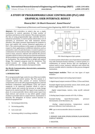
6- PROCESS IMAGE AREA: - I/P image [area/table], O/P
[image area/table].
BUS SYSTEM- bus system transmit data or signal between
input, output modules, cup and 3process.
TYPE OF PLC-
1- COMPACT and
2- MODULAR.
In compact plc memory are flexed I/P module, in Modular
I/p module depends on project or customer requirement.
Compact plc are less memory and modular plc depending on
project there used more memory. In compact any fault is
observed in any slot {i/p} so required change hardware
{plc’s}, in modular case of fault to any slot {i/p} can be easily
handle fault by replacing the slots.
LADDER LOGIC PROGRAMING USING SOFTWARE (RS
LINX, RS LOGIX 500, SIMATIC MANAGER)
One of the widely used methods of controlling PLCs is using
Ladder logic programming. The ladder logic diagram is a
representation of the steps of programming. INPUT address
can be used in series and parallel. OUTPUT address can be
used in parallel. OUTPUT address can be used as INPUT
address. INPUT address not be used as OUTPUT address.
INPUT address can be repeated as INPUT address. OUTPUT
latch and unlatch OUTPUT coil. The ladder program is all
PLCs follow a template that consists of 2 bus bars that are
connected to one another using rung lines.
FIG -RS LINX LITE
NOTE- RS LINX LITE is for configuration with RSLOGIX500.in
RSLOGIX 500 we chosen input/output configuration,
microcontroller etc. in this we design programs and run it
through RSLOGIX 500. Same in SIMATIC MANAGER SIMATIC
MANAGER are using for SIMESNS PLC.
FIG- RS LOGIX 500
FIG- SIMATIC MANAGER
CONCLUSION
A software tool and hardware for teaching/learning the
microcontroller based PLC, called EasyLadder, andhasbeen
presented. It can be used when describing the PLC
architecture, the Ladder logic instruction set or the
embedded peripherals operation, and also to write and test
Application programs. The main advantages of thisplatform
are its versatility, design flexibilityandlowcostcompared to
commercially available products as a teaching point of view.
It is considered that this platform has an impact in the
automation where PLC is the part of system and so student
can understand heart of the system. The source codes of
EasyLadder are open to studentsothateveryonemakestheir
own small PLC using editing the codes. Also, the authors
consider that this system is a platform on which a more
powerful PLC can be developed in future. The results of the
application of our approachtoeducationhavebeenexcellent
both in terms of student’s motivation and knowledge.](https://image.slidesharecdn.com/irjet-v5i10190-181102112502/85/IRJET-A-Study-of-Programmable-Logic-Controllers-PLC-and-Graphical-User-Interface-Result-2-320.jpg)
![International Research Journal of Engineering and Technology (IRJET) e-ISSN: 2395-0056
Volume: 05 Issue: 10 | Oct 2018 www.irjet.net p-ISSN: 2395-0072
© 2018, IRJET | Impact Factor value: 7.211 | ISO 9001:2008 Certified Journal | Page 1025
RESULT
This project we have learn how to design a program and
familiar to plc drives. Students are learn here how to create
program. The plc drives are typically chosen for interface
with program. Plc Drives are helping to run program and
monitoring. This project helps student to create program
and run through plc drive. Software is used to create
program and helps to understand it. Students can use this
project to understand plc programming and drive
understanding. This project helps to learners to understand
plc programming.
ACKNOWLEDGMENT
I am grateful to staff member of electronics and
communication department of RKD Institute of Science And
Technology, Bhopal (M.P.) for the opportunitytopursuethis
Master’s project in a specialized area of interest and wish to
express my sincere appreciation and gratitude to himforhis
guidance throughout the course of this project. My sincere
thank also to all other faculty members of the department
for their valuable suggestions and comments.
REFERENCE
[1] Michael Vine, “Visual Basic Programming (For the
absolute beginner)”.
[2] Vincet Himpe, “Visual Basic for electronics engineering
applications”.
[3] David I. Schneider, “Computer Programming Concepts
and Visual Basic”.
[4] Clayton Walnum, “Complete Idiot's Guide to Visual Basic
6” ISBN: 078971812x, Publication Date: 12/15/98.
[5] L.A. BRYAN and E.A. BRYAN.” ProgrammableControllers.
[6] Theory and implementation, by L.A. BRYAN and E.A.
BRYAN.
[7] Prolific Institute for Automation.
[8] Schuler Industrial Automation modules.](https://image.slidesharecdn.com/irjet-v5i10190-181102112502/85/IRJET-A-Study-of-Programmable-Logic-Controllers-PLC-and-Graphical-User-Interface-Result-3-320.jpg)

This document discusses programmable logic controllers (PLCs) and their use in industrial automation. It begins with an abstract that outlines how PLCs are widely used to control industrial machines and presents experiments for students to learn about various PLC applications. The next sections describe the basic components of a PLC system, including input/output modules, the central processing unit, and programming software. Ladder logic programming is discussed as a common method to control PLCs. The document concludes that the presented educational approach on PLCs is effective for teaching students about industrial automation and control systems.