Download to read offline
![International Research Journal of Engineering and Technology (IRJET) e-ISSN: 2395-0056
Volume: 09 Issue: 07 | July 2022 www.irjet.net p-ISSN: 2395-0072
© 2022, IRJET | Impact Factor value: 7.529 | ISO 9001:2008 Certified Journal | Page 2055
SMART LATHE MACHINE
Chigullapalli Rahul1, Polu Sankeerth2, Kalimera Uttej3, Kukkada Arun4, K.Raja sekhar5
1 Student, Mechanical department, Sreyas Institute of Engineering and Technology, Telangana, India.
2,3,4 Students, Mechanical department, Sreyas Institute of Engineering and Technology, Telangana, India.
5 Associate Professor, Dept. of Mechanical Engineering, Sreyas Institute of Engineering and Technology.
---------------------------------------------------------------------***---------------------------------------------------------------------
Abstract - In the present scenario, thelathemachineplaysa
vital role in the engineering division of the manufacturing
industry. While the manual lathe machines are economical,
their accuracy and efficiency are not up to the mark.
Contrarily, CNC machines deliver the desired accuracy and
efficiency but demand a significant investment in capital. In
order to address this issue, a smart lathe machineapproachto
the traditional lathe machine hasbeendeveloped. Itmakesuse
of sensors and actuators that can be managed by the Arduino
UNO microcontroller and NodeMCU. Therefore, switching
from manual to smart lathe machines can significantly
improve accuracy and efficiency while also controlling
investment costs, giving the manufacturing industry a much-
needed boost. This configuration enables a machinist to
inspect the workpiece's dimensions without removing it, as
well as display the chuck's speed and other features. Industry
4.0-inspired digital technologies are driving a new business
environment that is increasinglysustainable. Purchasing new-
generation machinery makes it possible to take advantage of
the many advantages of digitalization, including increased
productivity, flexibility, efficiency, and quality, reduced
resource consumption, and improved worker safety. By
combining mechanical, electronic, and software technologies,
the traditional lathe machine is transformed into a smart
lathe machine. For the sake of novelty, accuracy, and time-
decreasing, a conventional lathe machine has been converted
into a smart lathe machine by retrofitting to show readings of
the dimensions of the workpiece, speed of the chuck, motor
temperature, and distance from the headstocktothetailstock,
and it can be accessed by the RFID tags only.
Key Words: Manufacturing, Industrial revolution, IoT, Lead
time, Accuracy, Retrofitting, Remodification.
1.INTRODUCTION
A lathe machine uses a cutting tool to remove material from
the workpiece's surface. The workpiece is held in the chuck,
and the tool feeds material onto the workpiece to perform
various operations like cutting, drilling, knurling,
deformation, turning, and facing. It is one of the most
adaptable and frequently used machines in workplaces,
workshops, and educational institutions.
Retrofitting describes the situation in which modern
features or technology are added to older systems to update
their components and enhance their functionality. This
definition covers nearly all of theinformationabouttheterm
"retrofitting" as it also refers to the integration of new
features or technology into older systems. When retrofitting
is used in reference to traditional lathes, it refers to
modernizing the lathe and enhancing its productivity.
Repairing or replacing mechanical parts to the original, as-
new factory specificationsis knownasremanufacturing. The
machine will be completely disassembled, cleaned,
examined, repaired, and painted. Updates will bemadeto all
electrical, hydraulic, and pneumatic systems. To adapt the
machine for a different use, it may also be modified or given
mechanical accessories.Remanufacturing will almostalways
happen at the remanufacturer's location. The main goal of
incorporating a smart lathe machine into an existing
conventional lathe machine is to enhance it with features
such as non-contact workpiecedimensionmeasurement and
condition monitoring of the electrical components of the
lathe. [1]
The goals of retrofitting consist of
implementing new manufacturing techniques.
minimizing machine idling.
greater speeds.
decreased tool costs
friendly service.
increased output and improved machine control.
significantly greater repeatability
to reduce lead time,
very quick machining cycles.
high precision.
Retrofitting should be much less expensive overall than
buying a new system.
2. Sequence of upgrading
The fig 1 shows the conversion of a conventional lathe into a
smart lathe in different stages. There are different stages,
from selecting the sensors to programming them and
implementing them on the lathe machine.](https://image.slidesharecdn.com/irjet-v9i7377-221022112111-ae882590/75/SMART-LATHE-MACHINE-1-2048.jpg)
![International Research Journal of Engineering and Technology (IRJET) e-ISSN: 2395-0056
Volume: 09 Issue: 07 | July 2022 www.irjet.net p-ISSN: 2395-0072
© 2022, IRJET | Impact Factor value: 7.529 | ISO 9001:2008 Certified Journal | Page 2056
Fig -1: Stages of smart lathe retrofitting procedure
2.1 Sensors and actuators
The fig 2, block diagram, explains the different sensors and
actuators connectedtotheprogrammable boardssuchasthe
Arduino UNO and NodeMCU. The actuators still require a
12V power source even though all the electronic parts are
connected to 5V. The microcontroller gathers the sensor
data and uses the I2C communication protocol to send it to
the LCD. An Internet of Things (IoT) device called NodeMCU
can send data in formats that are readable by humans over
Wi-Fi. [2]
Fig -2: Sensor connectivity to microcontrollers
2.2 Circuit diagram
Fig -3: Electronic component connection
The fig 3 represents the connections of sensors, actuators,
relays, and other electronic components connected to the
Arduino and Nodemcu.
2.3 Software
Arduino is an open-source platform for prototyping that is
built on user-friendly hardware and software. Arduino
boards have the ability to read inputs, such as light from a
sensor or pressure from a finger on a button, and convert
them into outputs, such as turning on a motor or an LED. By
sending a set of instructions to the microcontroller, the user
can instruct the board what to do. The user should dothis by](https://image.slidesharecdn.com/irjet-v9i7377-221022112111-ae882590/75/SMART-LATHE-MACHINE-2-2048.jpg)
![International Research Journal of Engineering and Technology (IRJET) e-ISSN: 2395-0056
Volume: 09 Issue: 07 | July 2022 www.irjet.net p-ISSN: 2395-0072
© 2022, IRJET | Impact Factor value: 7.529 | ISO 9001:2008 Certified Journal | Page 2057
utilizing the Arduino Software (IDE), which is based on
Processing, and the Wiring-based Arduino Programming
Language (based on Wiring). Based on theATmega328P,the
Uno is a microcontroller board.
Fig -4: Arduino IDE
2.3.1 Arduino UNO
The ATmega328P microcontroller is the foundation of the
Arduino UNO. Comparatively speaking, it is simpler to use
than other boards like the Arduino Mega board, etc. The
board is made up of shields, other circuits, and digital and
analog Input/Output (I/O) pins. The Arduino UNO has 14
digital pins, a USB port, a power jack, and an ICSP (In-Circuit
Serial Programming) header, in addition to 6 analog pin
inputs. An IDE, or integrated development environment, is
the platform on which it is programmed. Both online and
offline platforms are compatible with it. The FTDI USB-to-
serial driver chip is absent from the Uno, setting it apart
from all previous boards. Instead, it uses an Atmega16U2
(Atmega8U2 up to version R2) that has been configured as a
USB-to-serial converter. The USB ports on your computer
are shielded from shorts and overcurrent by the resettable
poly-fuse on the Uno.
.
Fig -5: Arduino UNO[5]
2.3.2 NodeMCU
A low-cost System-on-a-Chip (SoC) called the ESP8266
serves as the foundation of the NodeMCU (Node
Microcontroller Unit), an open-source environment for
developing both software and hardware. The Espressif
Systems-designed and -produced ESP8266 has all of the
essential components of a computer, including CPU, RAM,
networking (Wi-Fi), and even a contemporary operating
system and SDK. Because of this, it is a great option for all
types of Internet of Things (IoT) projects.
Fig -6: NodeMCU [6]
2.4 List of IoT features
The below figure 7 shows list of IoT features to be given fora
conventional lathe machine to upgrade it into a smart lathe
machine](https://image.slidesharecdn.com/irjet-v9i7377-221022112111-ae882590/75/SMART-LATHE-MACHINE-3-2048.jpg)
![International Research Journal of Engineering and Technology (IRJET) e-ISSN: 2395-0056
Volume: 09 Issue: 07 | July 2022 www.irjet.net p-ISSN: 2395-0072
© 2022, IRJET | Impact Factor value: 7.529 | ISO 9001:2008 Certified Journal | Page 2058
Fig -7: Smart features given to mechanical elements
2.5 Working algorithm
Step 1) The “Arduino Software IDE” is initializedasshownin
Figure 4.
Step 2) Based on the input parameters, the program is
written accordingly.
Step 3) Written code must have the requirements of all the
sensors that should also be mentioned in the void setup, and
sensor information and connectionsareinitializedabovethe
void setup.
Step 4) The actual working model shouldbe writtenina void
loop so as to repeat the process in a loop manner.
Step 5) Now the coding is compiled. so that it ensures the
sketch is free to upload.
Step 6) These codes are transmitted to the Arduinoboard by
means of a USB cable.
Step 7) In the case of Nodemcu, the output of the written
code is checked on the serial monitor for debugging
purposes.
Step 8) Meanwhile, the workpiece is mounted on the chuck
of the smart lathe as shown in Figure 3.
Step9) Now, the Arduino reads the program and, based on
the input of the lathe, shows the output ontheLCDdisplayto
the machinist.
Step10) When the procedure is complete, adjusting the
potentiometer to the left and right will show the values of
additional parameters, such as spindle speed, motor
temperature, etc. [3][4]
Fig -8: Controller device
3. Working model
Fig -9: Working model of smart lathe prototype](https://image.slidesharecdn.com/irjet-v9i7377-221022112111-ae882590/75/SMART-LATHE-MACHINE-4-2048.jpg)

![International Research Journal of Engineering and Technology (IRJET) e-ISSN: 2395-0056
Volume: 09 Issue: 07 | July 2022 www.irjet.net p-ISSN: 2395-0072
© 2022, IRJET | Impact Factor value: 7.529 | ISO 9001:2008 Certified Journal | Page 2061
Fig -17: IR Sensor attached to spindle
Fig -18: Speed of the chuck
Fig -19: Workpiece length values
Fig -20: Ultrasonic sensor placed on toolpost
Improvements: The improvements after the lathe machine
are upgraded to smart lathe are as follows
1) Worker safety
2) Lead time
3) Non-contact measurement
4) Production rate
5) Security to the lathe
6. Conclusion
Low labor costs and high-quality outputarebenefitsofusing
a smart lathe machine. The smart lathe machine allows a
machinist to control the temperature of the machine and
turn it off while he is away. The current work is anticipated
to be helpful for the manufacturing industry as well as the
research community with regard to cost basis. Through a
series of design changes and the use of a retrofitting
technique, a conventional lathe machine can be converted
into a smart lathe machine. As a result, NodeMCU and
Arduino were successful in creating the design for the smart
lathe. which, thanks to the collaboration of hardware
(Arduino UNO) and software (Arduino IDE), has led to the
development of a semi-automated approach to the
traditional lathe machine. By adding a few new features to
the existing lathe, the newly created Arduino lathe's setup
cost is increased; however, when compared to the fully
automated/CNC machine, the setup cost is significantly
lower. The repeatability and dimensional stability of the
manufactured part are achieved due to the relatively high
accuracy of the job manufactured in a semi-automatedlathe.
REFERENCES
[1] Parmar, Prakash & Mehta, Nirajkumar. (2014).
Investigation on Automation of Lathe Machine.
International Journal of Emerging Technology and
Advanced Engineering. 4. 524.
[2] Abd-Alrazzaq, Mohamed & Ahmed,Mahmoud&Younes,
Mohammad. (2019). A computer numerical control
(CNC) multi-pass spinning solution to a center lathe
retrofit. SN Applied Sciences. 1. 10.1007/s42452-018-
0007-x.
[3] Sakthi, S & Niresh, J & Vignesh, K & Raj, Goutom. (2018).
Development of Semi-Automatic Lathe by using
Intelligent Soft Computing Technique. IOP Conference
Series: Materials Science and Engineering. 324.012053.
10.1088/1757-899X/324/1/012053.
[4] Ilari, Serena & Carlo, Fabio & Ciarapica, Filippo
Emanuele & Bevilacqua, Maurizio.(2021).MachineTool
Transition from Industry 3.0 to 4.0: A Comparison
between Old Machine Retrofitting and the Purchase of](https://image.slidesharecdn.com/irjet-v9i7377-221022112111-ae882590/75/SMART-LATHE-MACHINE-7-2048.jpg)
![International Research Journal of Engineering and Technology (IRJET) e-ISSN: 2395-0056
Volume: 09 Issue: 07 | July 2022 www.irjet.net p-ISSN: 2395-0072
© 2022, IRJET | Impact Factor value: 7.529 | ISO 9001:2008 Certified Journal | Page 2062
New Machines from a Triple Bottom Line Perspective.
Sustainability. 13. 10441. 10.3390/su131810441.
[5] Arduino UNO - JavaTpoint
[6] NodeMCU ESP8266 Pinout, Specifications, Features &
Datasheet (components101.com)](https://image.slidesharecdn.com/irjet-v9i7377-221022112111-ae882590/75/SMART-LATHE-MACHINE-8-2048.jpg)

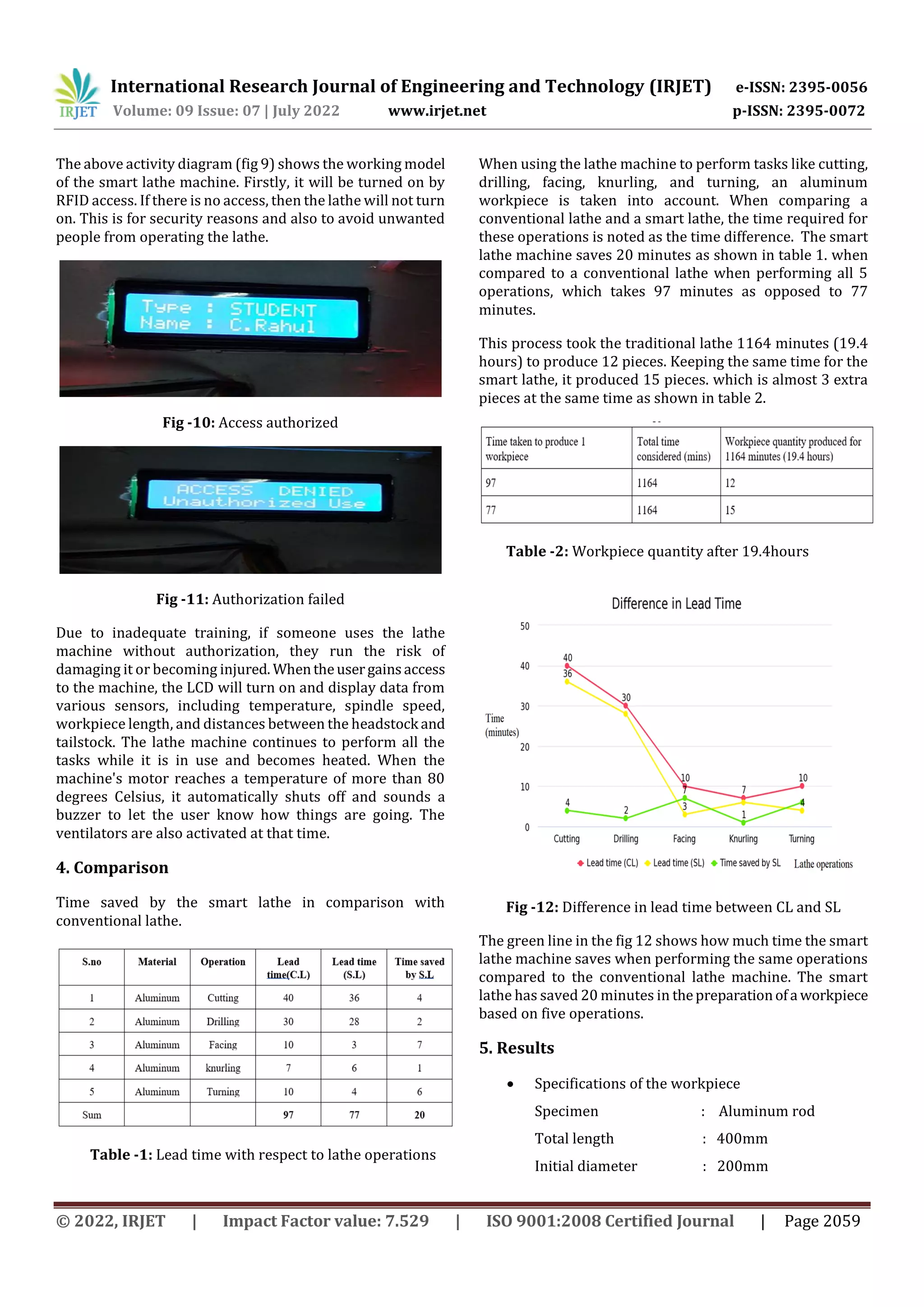
This document describes the retrofitting of a conventional lathe machine to create a smart lathe machine. Sensors and actuators are connected to microcontrollers like Arduino UNO and NodeMCU to monitor parameters like workpiece dimensions, chuck speed, motor temperature, and distance between the headstock and tailstock. This allows inspection of the workpiece without removing it and improves accuracy, efficiency, and production rates while reducing costs compared to a manual lathe. Testing showed the smart lathe saved 20 minutes of time per workpiece and could produce 3 more pieces in the same time period as a conventional lathe.


![INTERNSHIP_PIBOTS_GRP8 main[1] (1).pptxhwheheh](https://cdn.slidesharecdn.com/ss_thumbnails/internshippibotsgrp8main11-241016051934-50388b01-thumbnail.jpg?width=640&height=640&fit=bounds)