Downloaded 505 times

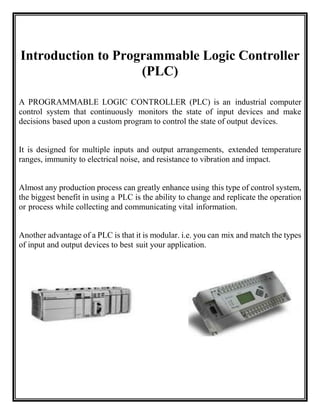
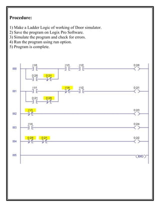
![Example of a simple ladder logic program
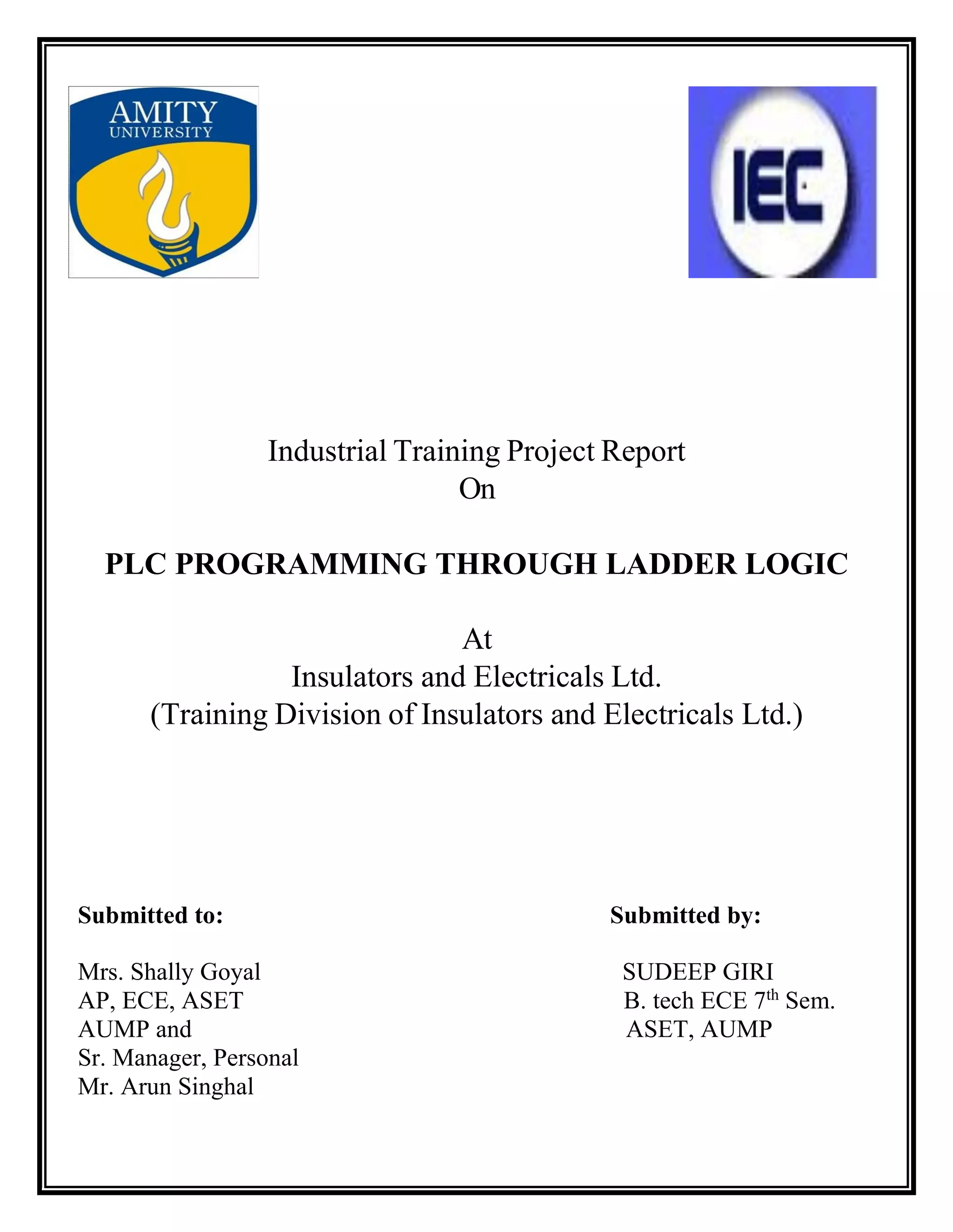
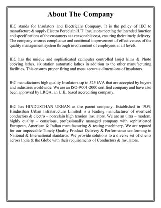
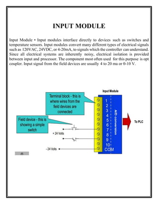
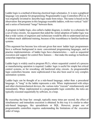
The language itself can be seen as a set of connections between logical checkers
(relay contacts) and actuators (coils). If a path can be traced between the left side of
the rung and the output, through asserted (true or "closed") contacts, the rung is true
and the output coil storage bit is asserted (1) or true. If no path can be traced, then
the output is false (0) and the "coil" by analogy to electromechanical relays is
considered "de-energized". The analogy between logical propositions and relay
contact status is due to Claude Shannon.
Ladder logic has "contacts" that "make" or "break" "circuits" to control "coils." Each
coil or contact corresponds to the status of a single bit in the programmable
controller's memory. Unlike electromechanical relays, a ladder program can refer any
number of times to the status of a single bit, equivalent to a relay with an indefinitely
large number of contacts.
So-called "contacts" may refer to inputs to the programmable controller from
physical devices such as pushbuttons and limit switches, or may represent the status
of internal storage bits which may be generated elsewhere in the program.
Each rung of ladder language typically has one coil at the far right. Some
manufacturers may allow more than one output coil on a rung.
--( )-- a regular coil, true when its rung is true
--()-- a "not" coil, false when its rung is true
--[ ]-- A regular contact, true when its coil is true (normally false)
--[]-- A "not" contact, false when its coil is true (normally true)
The "coil" (output of a rung) may represent a physical output which operates some
device connected to the programmable controller, or may represent an internal
storage bit for use elsewhere in the program.](https://image.slidesharecdn.com/sipsudeep-151129115245-lva1-app6891/85/Summer-Internship-Report-on-PLC-18-320.jpg)
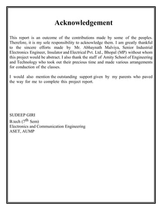
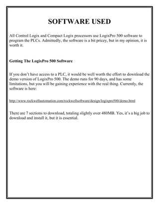
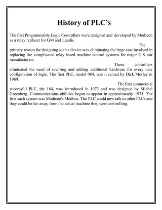
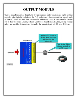
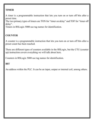
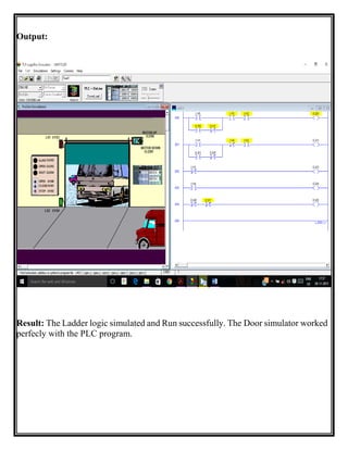
![Generally Used Instructions & symbol for PLC Programming
Input Instruction
--[ ]-- This Instruction is Called IXC or Examine If Closed.
If a NO switch is actuated, then only this instruction will be true. If a NC switch is
actuated, then this instruction will not be true and hence output will not be generated.
--[]--
This Instruction is Called IXO or Examine If Open.
If a
NC switch is actuated, then only this instruction will be true. If a NC switch is
actuated, then this instruction will not be true and hence output will not be generated.
Output Instruction
--( )--This Instruction Shows the States of Output.
i.e.; If any instruction either XIO or XIC is true then output will be high. Due to high
output a 24-volt signal is generated from PLC processor.
Rung
Rung is a simple line on which instruction are placed and logics are created
E.g.: ---------------------------------------------](https://image.slidesharecdn.com/sipsudeep-151129115245-lva1-app6891/85/Summer-Internship-Report-on-PLC-19-320.jpg)
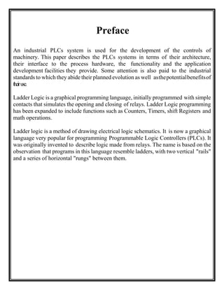
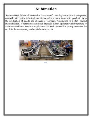
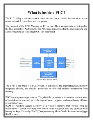
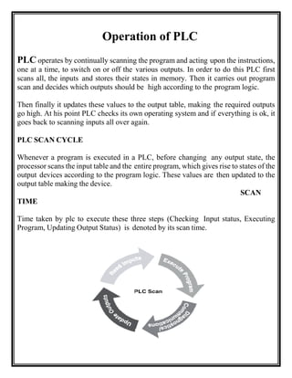
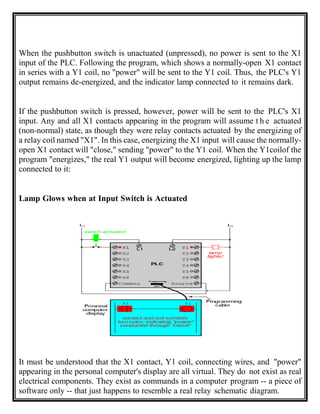
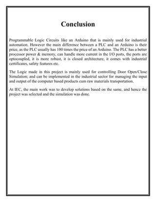
![This system allows very complex logic designs to be broken down and evaluated.
Practical Examples
Example-1
------[ ]--------------[ ]----------------O---
Key Switch 1 Key Switch 2 Door Motor
This circuit shows two key switches that security guards might use to activate an
electric motor on a bank vault door. When the normally open contacts of both
switches close, electricity is able to flow to the motor which opens the door. This is
a logical AND.
Example-2
Often we have a little green "start" button to turn on a motor, and we want to
turn it off with a big red "Stop" button.
--+----[ ]--+----[]----( )---
| start | stop run
| |
+----[ ]--+
run
-------[ ]--------------( )---
run motor
Example With PLC](https://image.slidesharecdn.com/sipsudeep-151129115245-lva1-app6891/85/Summer-Internship-Report-on-PLC-21-320.jpg)
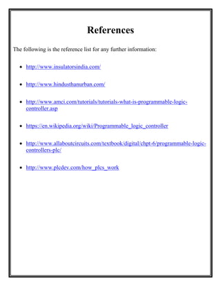
![Consider the following circuit and PLC program:
-------[ ]--------------( )---
run motor](https://image.slidesharecdn.com/sipsudeep-151129115245-lva1-app6891/85/Summer-Internship-Report-on-PLC-22-320.jpg)
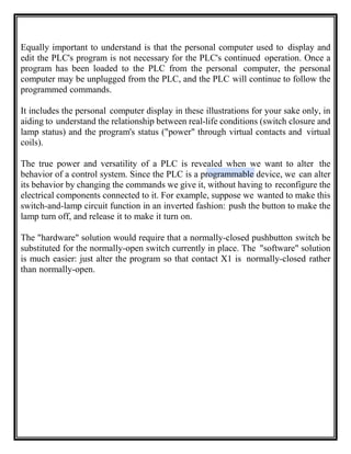
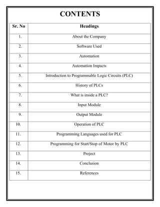
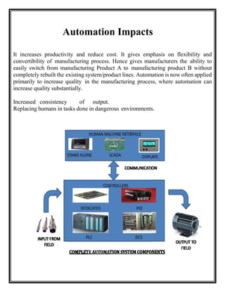
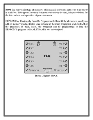
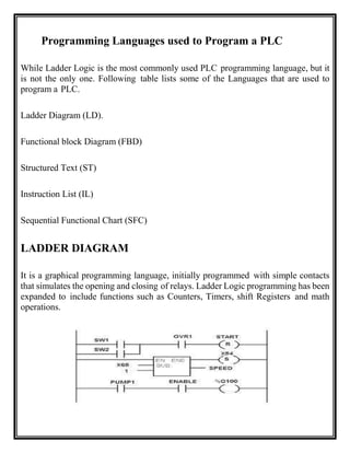
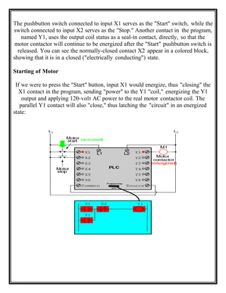
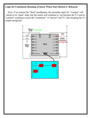
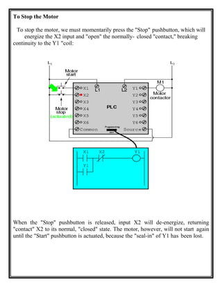
![Programming for Start/Stop of Motor by PLC
Often we have a little green "start" button to turn on a motor, and we want to turn
it off with a big red "Stop" button.
--+----[ ]--+----[]----( )---
| start | stop run
| |
+----[ ]--+
run](https://image.slidesharecdn.com/sipsudeep-151129115245-lva1-app6891/85/Summer-Internship-Report-on-PLC-25-320.jpg)

The document provides information about an industrial training project completed by Sudeep Giri at Insulators and Electricals Ltd. It includes an acknowledgement, preface, and table of contents. The content covers topics like the company background, software used, automation, PLC components, programming languages, and a motor start/stop example. It aims to describe PLC programming through ladder logic based on the training received.


