Download free for 30 days
Sign in
Upload
Language (EN)
Support
Business
Mobile
Social Media
Marketing
Technology
Art & Photos
Career
Design
Education
Presentations & Public Speaking
Government & Nonprofit
Healthcare
Internet
Law
Leadership & Management
Automotive
Engineering
Software
Recruiting & HR
Retail
Sales
Services
Science
Small Business & Entrepreneurship
Food
Environment
Economy & Finance
Data & Analytics
Investor Relations
Sports
Spiritual
News & Politics
Travel
Self Improvement
Real Estate
Entertainment & Humor
Health & Medicine
Devices & Hardware
Lifestyle
Change Language
Language
English
Español
Português
Français
Deutsche
Cancel
Save
Submit search
EN
Uploaded by
IRJET Journal
152 views
DESIGN AND DEVELOPMENT OF BATTERY THERMAL MANAGEMENT SYSTEM USING PHASE CHANGE MATERIAL AND FINS TO IMPROVE BATTERY LIFE
https://www.irjet.net/archives/V11/i2/IRJET-V11I204.pdf
Engineering
◦
Read more
0
Save
Share
Embed
Embed presentation
Download
Download to read offline
1
/ 5
2
/ 5
Most read
3
/ 5
4
/ 5
5
/ 5
More Related Content
PDF
Design and development of cooling system of battery in an electric two wheeler
by
IRJET Journal
PDF
Thermal Management of Lithium-Ion Battery in Electric Vehicle
by
IRJET Journal
PPTX
Thermal Runaway.pptx, THERMAL RUNWAY PROBLEM IN EVS BATTERY
by
naikatharva2504
PDF
“Optimization of battery Cooling system for electric vehicle using Simulation”
by
IRJET Journal
PDF
Design, Optimization, and Analysis of Electric vehicle Battery Pack
by
IRJET Journal
PDF
THERMAL MANAGEMENT IN EV
by
IRJET Journal
PPTX
Designing of smart battery enclosure development
by
DeepakChahar12
PDF
Engineering Project Portfolio
by
Jiankun Pu
Design and development of cooling system of battery in an electric two wheeler
by
IRJET Journal
Thermal Management of Lithium-Ion Battery in Electric Vehicle
by
IRJET Journal
Thermal Runaway.pptx, THERMAL RUNWAY PROBLEM IN EVS BATTERY
by
naikatharva2504
“Optimization of battery Cooling system for electric vehicle using Simulation”
by
IRJET Journal
Design, Optimization, and Analysis of Electric vehicle Battery Pack
by
IRJET Journal
THERMAL MANAGEMENT IN EV
by
IRJET Journal
Designing of smart battery enclosure development
by
DeepakChahar12
Engineering Project Portfolio
by
Jiankun Pu
Similar to DESIGN AND DEVELOPMENT OF BATTERY THERMAL MANAGEMENT SYSTEM USING PHASE CHANGE MATERIAL AND FINS TO IMPROVE BATTERY LIFE
PDF
EV Battery Protection System
by
IRJET Journal
PPT
GCoreLab Thermal Solution for Electric Vehicle
by
GCoreLab Private Ltd.
PDF
Design and Analysis of a Cooling System for High Voltage Battery Pack of a Fo...
by
IRJET Journal
PDF
battery-thermal-management-in-evs-and-hevs-issues-and.pdf
by
CHANDAMAMATV
PPTX
Phase changing material in batteryPresentation_RP & SC.pptx
by
SCConstruction
PPTX
2013.10.18 alfred piggott gentherm nrel sae thermoelectric battery thermal ma...
by
ap3slidshare
PPTX
Thermal behaviour of lithium ion phosphate battery
by
NandakumarPradeep
PPTX
Integrated ev bms for charging and fire safety
by
BHUVANASUEE22012
PPTX
final project.pptx of coolant system in a car
by
KarriSivaSadhvik
PPTX
ENHANCING EV SAFETY PERFORMANCE THROUGH ADVANCED BATTERY THERMAL MANAGEMENT ....
by
VootlaMahesh
PDF
Lithium Ion Battery Module Thermal Management System
by
Kulwinder Basuta
PPTX
4-2Presentation_BTMS_Manoj Kumar Desu.pptx
by
SriKalyanaRamaJyosyu
PPTX
NEXT-GEN THERMAL MANAGEMENT: FASTER CHARGING, EXTENDED RANGE, AND PROPAGATIO...
by
iQHub
PDF
IRJET - A Review on Design and Optimization of Cooling Plate for Battery Modu...
by
IRJET Journal
PDF
SAE_Published
by
Laura Nash
PDF
Comparative analysis of Thermal insulating material in Lithium ion batteries ...
by
vivatechijri
PPTX
impact of climate change by batterey.pptx
by
SCConstruction
PPTX
Thermal behaviour of lithium ion phosphate battery
by
Vishwa Jayakumar
PPTX
Lithium Battery Thermal Degradation Behavioral Trends
by
bdevyani
PDF
Evlib2009forum4
by
jatpack
EV Battery Protection System
by
IRJET Journal
GCoreLab Thermal Solution for Electric Vehicle
by
GCoreLab Private Ltd.
Design and Analysis of a Cooling System for High Voltage Battery Pack of a Fo...
by
IRJET Journal
battery-thermal-management-in-evs-and-hevs-issues-and.pdf
by
CHANDAMAMATV
Phase changing material in batteryPresentation_RP & SC.pptx
by
SCConstruction
2013.10.18 alfred piggott gentherm nrel sae thermoelectric battery thermal ma...
by
ap3slidshare
Thermal behaviour of lithium ion phosphate battery
by
NandakumarPradeep
Integrated ev bms for charging and fire safety
by
BHUVANASUEE22012
final project.pptx of coolant system in a car
by
KarriSivaSadhvik
ENHANCING EV SAFETY PERFORMANCE THROUGH ADVANCED BATTERY THERMAL MANAGEMENT ....
by
VootlaMahesh
Lithium Ion Battery Module Thermal Management System
by
Kulwinder Basuta
4-2Presentation_BTMS_Manoj Kumar Desu.pptx
by
SriKalyanaRamaJyosyu
NEXT-GEN THERMAL MANAGEMENT: FASTER CHARGING, EXTENDED RANGE, AND PROPAGATIO...
by
iQHub
IRJET - A Review on Design and Optimization of Cooling Plate for Battery Modu...
by
IRJET Journal
SAE_Published
by
Laura Nash
Comparative analysis of Thermal insulating material in Lithium ion batteries ...
by
vivatechijri
impact of climate change by batterey.pptx
by
SCConstruction
Thermal behaviour of lithium ion phosphate battery
by
Vishwa Jayakumar
Lithium Battery Thermal Degradation Behavioral Trends
by
bdevyani
Evlib2009forum4
by
jatpack
More from IRJET Journal
PDF
Auto-Charging E-Vehicle with its battery Management.
by
IRJET Journal
PDF
Auto-Charging E-Vehicle with its battery Management.
by
IRJET Journal
PDF
Advancements in CFD Analysis of Shell and Tube Heat Exchangers with Nanofluid...
by
IRJET Journal
PDF
Utilizing Biomedical Waste for Sustainable Brick Manufacturing: A Novel Appro...
by
IRJET Journal
PDF
Kiona – A Smart Society Automation Project
by
IRJET Journal
PDF
A Review on Influence of Fluid Viscous Damper on The Behaviour of Multi-store...
by
IRJET Journal
PDF
Explainable AI(XAI) using LIME and Disease Detection in Mango Leaf by Transfe...
by
IRJET Journal
PDF
Enhanced heart disease prediction using SKNDGR ensemble Machine Learning Model
by
IRJET Journal
PDF
Wireless Arduino Control via Mobile: Eliminating the Need for a Dedicated Wir...
by
IRJET Journal
PDF
Analysis of high energy charge particle in the Heliosphere
by
IRJET Journal
PDF
The Project Manager as an ambassador of the contract. The case of NEC4 ECC co...
by
IRJET Journal
PDF
Wireless Arduino Control via Mobile: Eliminating the Need for a Dedicated Wir...
by
IRJET Journal
PDF
A Novel System for Recommending Agricultural Crops Using Machine Learning App...
by
IRJET Journal
PDF
Breast Cancer Detection using Computer Vision
by
IRJET Journal
PDF
SPACE WATCH YOUR REAL-TIME SPACE INFORMATION HUB
by
IRJET Journal
PDF
BRAIN TUMOUR DETECTION AND CLASSIFICATION
by
IRJET Journal
PDF
Invest in Innovation: Empowering Ideas through Blockchain Based Crowdfunding
by
IRJET Journal
PDF
"Enhanced Heat Transfer Performance in Shell and Tube Heat Exchangers: A CFD ...
by
IRJET Journal
PDF
FIR filter-based Sample Rate Convertors and its use in NR PRACH
by
IRJET Journal
PDF
Analysis of high energy charge particle in the Heliosphere
by
IRJET Journal
Auto-Charging E-Vehicle with its battery Management.
by
IRJET Journal
Auto-Charging E-Vehicle with its battery Management.
by
IRJET Journal
Advancements in CFD Analysis of Shell and Tube Heat Exchangers with Nanofluid...
by
IRJET Journal
Utilizing Biomedical Waste for Sustainable Brick Manufacturing: A Novel Appro...
by
IRJET Journal
Kiona – A Smart Society Automation Project
by
IRJET Journal
A Review on Influence of Fluid Viscous Damper on The Behaviour of Multi-store...
by
IRJET Journal
Explainable AI(XAI) using LIME and Disease Detection in Mango Leaf by Transfe...
by
IRJET Journal
Enhanced heart disease prediction using SKNDGR ensemble Machine Learning Model
by
IRJET Journal
Wireless Arduino Control via Mobile: Eliminating the Need for a Dedicated Wir...
by
IRJET Journal
Analysis of high energy charge particle in the Heliosphere
by
IRJET Journal
The Project Manager as an ambassador of the contract. The case of NEC4 ECC co...
by
IRJET Journal
Wireless Arduino Control via Mobile: Eliminating the Need for a Dedicated Wir...
by
IRJET Journal
A Novel System for Recommending Agricultural Crops Using Machine Learning App...
by
IRJET Journal
Breast Cancer Detection using Computer Vision
by
IRJET Journal
SPACE WATCH YOUR REAL-TIME SPACE INFORMATION HUB
by
IRJET Journal
BRAIN TUMOUR DETECTION AND CLASSIFICATION
by
IRJET Journal
Invest in Innovation: Empowering Ideas through Blockchain Based Crowdfunding
by
IRJET Journal
"Enhanced Heat Transfer Performance in Shell and Tube Heat Exchangers: A CFD ...
by
IRJET Journal
FIR filter-based Sample Rate Convertors and its use in NR PRACH
by
IRJET Journal
Analysis of high energy charge particle in the Heliosphere
by
IRJET Journal
Recently uploaded
PDF
ACI 318-2205_American Concrete Institute.pdf
by
ericaguilerasoto1
PDF
Handheld_Laser_Welding_Presentation 2.pdf
by
sinezioveluz
PDF
Albert Pintoy - Specializing In Low-Latency
by
Albert Pintoy
PPTX
UnrealGameplayAbilitySystemPresentation.pptx
by
BenHowenstein
PPTX
Emerging Trends and Research Frontiers in Chemical Engineering for Green and ...
by
Chemical Engineering Dept. NIT Rourkela-769008, Odisha, India
PPTX
ISO 14224 Compliance & CMMS Software — A Comprehensive Guide for Reliable Mai...
by
MaintWiz Technologies Private Limited
PPTX
firewall Selection in production life pptx
by
ssuserb1479b
PPT
63490613-Boiler-Tube-Leakage-analysis-symptoms-causes.ppt
by
allahdittashafi
PPT
new Introduction to PACS.ppt Picture Archieving and communication and medicine
by
ssuserf3d7af
PPTX
Optimizing Plant Maintenance — Key Elements of a Successful Maintenance Plan ...
by
MaintWiz Technologies Private Limited
PPTX
How to Select the Right CMMS Software for Your Organization — A Complete Buye...
by
MaintWiz Technologies Private Limited
PPTX
Salesforce Bulk Connector V1 and V2 Deep Dive!
by
RajeevRanjan368982
PPTX
How to Create an Effective Monthly Maintenance Plan for Reliable Plant Operat...
by
MaintWiz Technologies Private Limited
PPT
Software Engineering Unit-1 presentation for students
by
kumari157687
PPTX
The Importance of Maintenance Budgets — Maximize Reliability & Control Costs ...
by
MaintWiz Technologies Private Limited
PPTX
22304_BCO_CO3_LO4_PPT MSBTE Building construction.pptx
by
PrasadBahekar4
PPTX
Revolutionizing Facilities Management with MaintWiz — AI CMMS for Smart FMaaS
by
MaintWiz Technologies Private Limited
PPTX
Power point presentation on introduction of software engineering
by
s6050748
PPTX
Optimizing Operations: Key Elements of a Successful Plant Maintenance Plan — ...
by
MaintWiz Technologies Private Limited
PDF
Hybrid Anomaly Detection Mechanism for IOT Networks
by
IJCNCJournal
ACI 318-2205_American Concrete Institute.pdf
by
ericaguilerasoto1
Handheld_Laser_Welding_Presentation 2.pdf
by
sinezioveluz
Albert Pintoy - Specializing In Low-Latency
by
Albert Pintoy
UnrealGameplayAbilitySystemPresentation.pptx
by
BenHowenstein
Emerging Trends and Research Frontiers in Chemical Engineering for Green and ...
by
Chemical Engineering Dept. NIT Rourkela-769008, Odisha, India
ISO 14224 Compliance & CMMS Software — A Comprehensive Guide for Reliable Mai...
by
MaintWiz Technologies Private Limited
firewall Selection in production life pptx
by
ssuserb1479b
63490613-Boiler-Tube-Leakage-analysis-symptoms-causes.ppt
by
allahdittashafi
new Introduction to PACS.ppt Picture Archieving and communication and medicine
by
ssuserf3d7af
Optimizing Plant Maintenance — Key Elements of a Successful Maintenance Plan ...
by
MaintWiz Technologies Private Limited
How to Select the Right CMMS Software for Your Organization — A Complete Buye...
by
MaintWiz Technologies Private Limited
Salesforce Bulk Connector V1 and V2 Deep Dive!
by
RajeevRanjan368982
How to Create an Effective Monthly Maintenance Plan for Reliable Plant Operat...
by
MaintWiz Technologies Private Limited
Software Engineering Unit-1 presentation for students
by
kumari157687
The Importance of Maintenance Budgets — Maximize Reliability & Control Costs ...
by
MaintWiz Technologies Private Limited
22304_BCO_CO3_LO4_PPT MSBTE Building construction.pptx
by
PrasadBahekar4
Revolutionizing Facilities Management with MaintWiz — AI CMMS for Smart FMaaS
by
MaintWiz Technologies Private Limited
Power point presentation on introduction of software engineering
by
s6050748
Optimizing Operations: Key Elements of a Successful Plant Maintenance Plan — ...
by
MaintWiz Technologies Private Limited
Hybrid Anomaly Detection Mechanism for IOT Networks
by
IJCNCJournal
DESIGN AND DEVELOPMENT OF BATTERY THERMAL MANAGEMENT SYSTEM USING PHASE CHANGE MATERIAL AND FINS TO IMPROVE BATTERY LIFE
1.
International Research Journal
of Engineering and Technology (IRJET) e-ISSN: 2395-0056 Volume: 11 Issue: 02 | Feb 2024 www.irjet.net p-ISSN: 2395-0072 DESIGN AND DEVELOPMENT OF BATTERY THERMAL MANAGEMENT SYSTEM USING PHASE CHANGE MATERIAL AND FINS TO IMPROVE BATTERY LIFE Tanaya P. Jagtap1, Heramb S. Khandve1, Parth J. Khedekar1, Pranjali R. Tete2 1U.G. Student, Dept. of Mechanical Engineering, AISSMS COE, Pune, India 2 Assistant Professor, Dept. of Mechanical Engineering, AISSMS COE, Pune, India ---------------------------------------------------------------------***--------------------------------------------------------------------- Abstract - Even though India has seen many advancements in regards to Electric Vehicles, one of the main issues Indian EVs are facing is dealing with the temperature irregularities within the battery pack, effective cooling systems and sudden fires to batteries. Though adapting to new techniques is essential, cost cutting, compactness of the system and optimal weight of the battery should be looked after as well. A battery thermal managementsystem with phasechangematerial with silica, aluminum fins and perforated slots is developed which effectively improves the battery working condition. An intricate system based on multipurpose dry chemical fine powder, which would act on extreme conditions of fire and thus cease the spread of fire and protect the vehicle and the passengers has been developed. An effective battery thermal management system can significantlyreducethechancesofan EV battery catching fire, maintain the temperature distribution within the battery pack and thus improve the life of a battery. Key Words: Phase Change Material (PCM), Silica, Battery Pack, Effective Cooling, BatteryThermalManagementSystem, Electric Vehicle, Fins. 1. INTRODUCTION Currently in India, Government is enforcing the stringent emission norms for the internal combustion engines driven vehicle. Hence the vehicle manufacturers have to shift their focus to the manufacturing of the electric vehicles. One of the challenges is to develop an efficient battery thermal management system for an electric vehicle. This system also applies to a large number of different vehicle applications, ranging from the compact car to the multi-utility vehicle and from the low-level hybrid vehicle to the entirely electrically- driven vehicle. Thus, it becomes necessary to develop highly efficient energy storage devices for the same. The attraction of the electronics market towards lithium-ion battery as an energy storage device is increasing primarily due to its high energy density, capacity, long cycle life and low self-discharge rate [1]. Li-ion batteries are very sensitive to the temperature. Inside these batteries, during charge and discharge processes, like any rechargeable batteries, heat is generated that causes to increase their temperatures. This increase in temperature has two different effects on the batteries.Thebeneficialeffect is that, by increasing the temperature, Li-ion batteries work more efficiently and their performance becomes better. On the other hand, the unfavorable effect is that, they are closer to thermal runaway that decreasestheirreliabilitybecauseof probable explosion [2]. 1.1 OBJECTIVES 2. To study the feasibility of phase change material in lithium-ion batteries. 3. To use the phase change material with additivesandpin fins heat sinks in batteries for better heat dissipation. 4. To set an experimental setup of a battery pack with PCM, pin fins and fine powder. 5. To analyze the proposed design and compare it with a standard battery pack of an EV bike. 1.2 SCOPE Battery Thermal Management with PCM presents more effective thermal performance. The pin fins decrease bulk temperature and improve temperature uniformity. Hybrid cooling effect shows an effective rate of heat dissipation. Provision of vent helps protect battery enclosure. 2. MATERIAL & EXPERIMENTAL TECHNOLOGIES In response to safety concerns surrounding OLA S1 PRO batteries, a scaled-down analysis has been undertaken, with data representing 1/20th of the battery pack. This deliberate reduction aims to facilitate controlled testing and evaluation, given reported incidents of the original batteries exhibiting safety issues, including a notable risk of catching fire. The consideration of data of 1/20TH of the OLA S1 PRO battery pack is as follows: The number of battery cells connected in series Ncs [-] in a string is calculated by dividing the nominal battery pack voltage Ubp [V] to the voltage of each battery cell Ubc [V]. The number of strings must be an integer. Therefore, theresult of the calculation is rounded to the higher integer. © 2024, IRJET | Impact Factor value: 8.226 | ISO 9001:2008 Certified Journal | Page 25
2.
International Research Journal
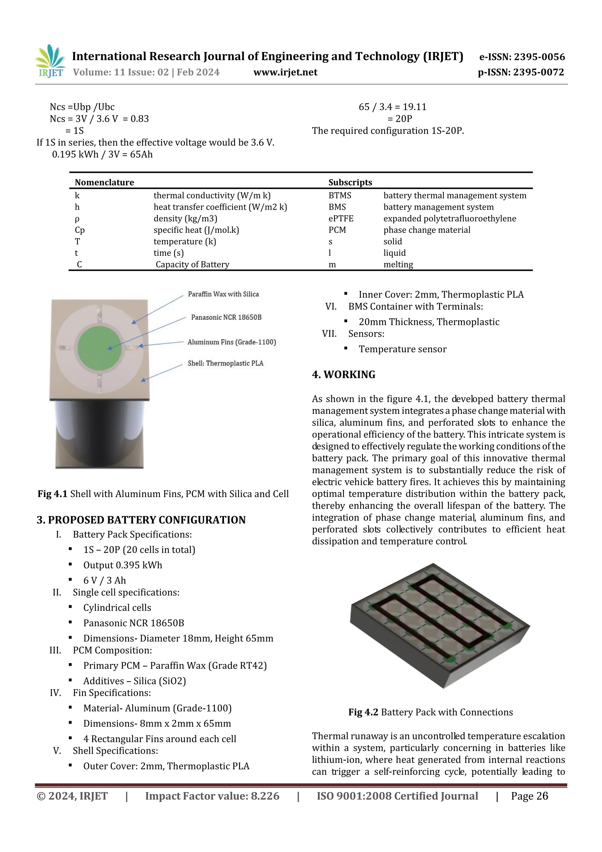
of Engineering and Technology (IRJET) e-ISSN: 2395-0056 Volume: 11 Issue: 02 | Feb 2024 www.irjet.net p-ISSN: 2395-0072 Ncs =Ubp /Ubc Ncs = 3V / 3.6 V = 0.83 = 1S If 1S in series, then the effective voltage would be 3.6 V. 0.195 kWh / 3V = 65Ah 65 / 3.4 = 19.11 = 20P The required configuration 1S-20P. Nomenclature Subscripts k thermal conductivity (W/m k) BTMS battery thermal management system h heat transfer coefficient (W/m2 k) BMS battery management system ρ density (kg/m3) ePTFE expanded polytetrafluoroethylene Cp specific heat (J/mol.k) PCM phase change material T temperature (k) s solid t time (s) l liquid C Capacity of Battery m melting Fig 4.1 Shell with Aluminum Fins, PCM with Silica and Cell 3. PROPOSED BATTERY CONFIGURATION I. Battery Pack Specifications: ▪ 1S – 20P (20 cells in total) ▪ Output 0.395 kWh ▪ 6 V / 3 Ah II. Single cell specifications: ▪ Cylindrical cells ▪ Panasonic NCR 18650B ▪ Dimensions- Diameter 18mm, Height 65mm III. PCM Composition: ▪ Primary PCM – Paraffin Wax (Grade RT42) ▪ Additives – Silica (SiO2) IV. Fin Specifications: ▪ Material- Aluminum (Grade-1100) ▪ Dimensions- 8mm x 2mm x 65mm ▪ 4 Rectangular Fins around each cell V. Shell Specifications: ▪ Outer Cover: 2mm, Thermoplastic PLA ▪ Inner Cover: 2mm, Thermoplastic PLA VI. BMS Container with Terminals: ▪ 20mm Thickness, Thermoplastic VII. Sensors: ▪ Temperature sensor 4. WORKING As shown in the figure 4.1, the developed battery thermal management system integratesaphasechangematerialwith silica, aluminum fins, and perforated slots to enhance the operational efficiency of the battery. This intricate system is designed to effectively regulate the working conditionsofthe battery pack. The primary goal of this innovative thermal management system is to substantially reduce the risk of electric vehicle battery fires. It achieves this by maintaining optimal temperature distribution within the battery pack, thereby enhancing the overall lifespan of the battery. The integration of phase change material, aluminum fins, and perforated slots collectively contributes to efficient heat dissipation and temperature control. Fig 4.2 Battery Pack with Connections Thermal runaway is an uncontrolled temperature escalation within a system, particularly concerning in batteries like lithium-ion, where heat generated from internal reactions can trigger a self-reinforcing cycle, potentially leading to © 2024, IRJET | Impact Factor value: 8.226 | ISO 9001:2008 Certified Journal | Page 26
3.
International Research Journal
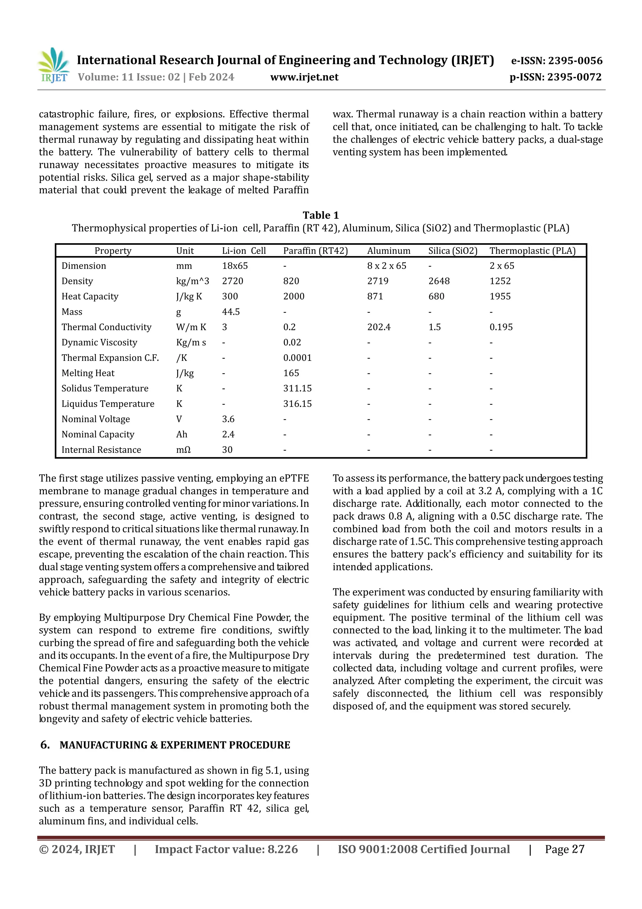
of Engineering and Technology (IRJET) e-ISSN: 2395-0056 Volume: 11 Issue: 02 | Feb 2024 www.irjet.net p-ISSN: 2395-0072 catastrophic failure, fires, or explosions. Effective thermal management systems are essential to mitigate the risk of thermal runaway by regulating and dissipating heat within the battery. The vulnerability of battery cells to thermal runaway necessitates proactive measures to mitigate its potential risks. Silica gel, served as a major shape-stability material that could prevent the leakage of melted Paraffin wax. Thermal runaway is a chain reaction within a battery cell that, once initiated, can be challenging to halt. To tackle the challenges of electric vehicle battery packs, a dual-stage venting system has been implemented. Table 1 Thermophysical properties of Li-ion cell, Paraffin (RT 42), Aluminum, Silica (SiO2) and Thermoplastic (PLA) The first stage utilizes passive venting, employing an ePTFE membrane to manage gradual changes in temperature and pressure, ensuring controlled ventingforminorvariations.In contrast, the second stage, active venting, is designed to swiftly respond to critical situations like thermalrunaway.In the event of thermal runaway, the vent enables rapid gas escape, preventing the escalation of the chain reaction. This dual stage ventingsystemoffersacomprehensiveand tailored approach, safeguarding the safety and integrity of electric vehicle battery packs in various scenarios. By employing Multipurpose Dry Chemical Fine Powder, the system can respond to extreme fire conditions, swiftly curbing the spread of fire and safeguarding both the vehicle and its occupants. In the event of a fire, the Multipurpose Dry Chemical Fine Powder acts as a proactivemeasuretomitigate the potential dangers, ensuring the safety of the electric vehicle and its passengers. Thiscomprehensiveapproachofa robust thermal management system in promoting both the longevity and safety of electric vehicle batteries. 6. MANUFACTURING & EXPERIMENT PROCEDURE The battery pack is manufactured as shown in fig 5.1, using 3D printing technology and spot welding for the connection of lithium-ion batteries. The design incorporateskeyfeatures such as a temperature sensor, Paraffin RT 42, silica gel, aluminum fins, and individual cells. To assess its performance, the battery packundergoestesting with a load applied by a coil at 3.2 A, complying with a 1C discharge rate. Additionally, each motor connected to the pack draws 0.8 A, aligning with a 0.5C discharge rate. The combined load from both the coil and motors results in a discharge rate of 1.5C. This comprehensive testing approach ensures the battery pack's efficiency and suitability for its intended applications. The experiment was conducted by ensuring familiarity with safety guidelines for lithium cells and wearing protective equipment. The positive terminal of the lithium cell was connected to the load, linking it to the multimeter. The load was activated, and voltage and current were recorded at intervals during the predetermined test duration. The collected data, including voltage and current profiles, were analyzed. After completing the experiment, the circuit was safely disconnected, the lithium cell was responsibly disposed of, and the equipment was stored securely. Property Unit Li-ion Cell Paraffin (RT42) Aluminum Silica (SiO2) Thermoplastic (PLA) Dimension mm 18x65 - 8 x 2 x 65 - 2 x 65 Density kg/m^3 2720 820 2719 2648 1252 Heat Capacity J/kg K 300 2000 871 680 1955 Mass g 44.5 - - - - Thermal Conductivity W/m K 3 0.2 202.4 1.5 0.195 Dynamic Viscosity Kg/m s - 0.02 - - - Thermal Expansion C.F. /K - 0.0001 - - - Melting Heat J/kg - 165 - - - Solidus Temperature K - 311.15 - - - Liquidus Temperature K - 316.15 - - - Nominal Voltage V 3.6 - - - - Nominal Capacity Ah 2.4 - - - - Internal Resistance mΩ 30 - - - - © 2024, IRJET | Impact Factor value: 8.226 | ISO 9001:2008 Certified Journal | Page 27
4.
International Research Journal
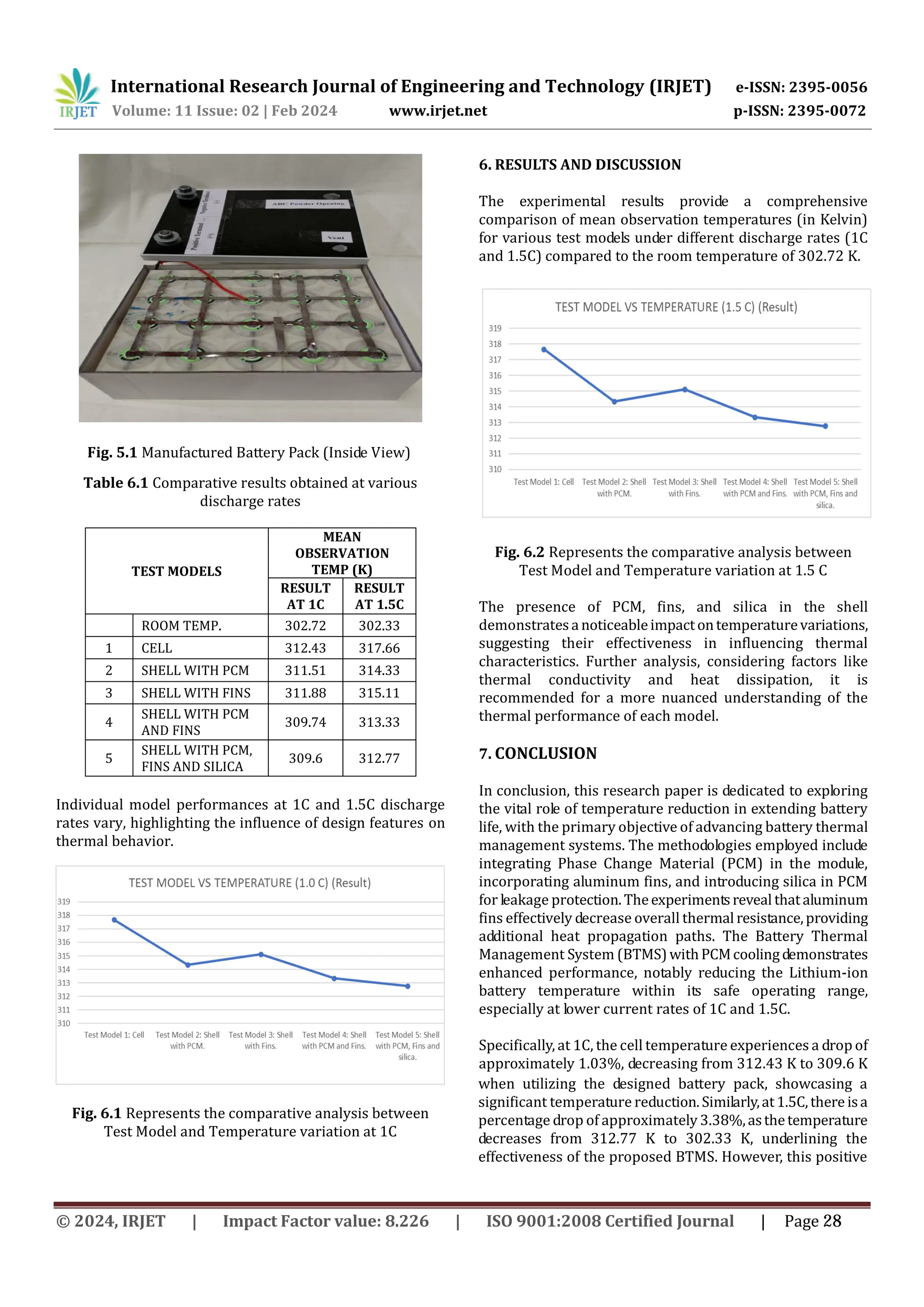
of Engineering and Technology (IRJET) e-ISSN: 2395-0056 Volume: 11 Issue: 02 | Feb 2024 www.irjet.net p-ISSN: 2395-0072 Table 6.1 Comparative results obtained at various discharge rates TEST MODELS MEAN OBSERVATION TEMP (K) RESULT AT 1C RESULT AT 1.5C ROOM TEMP. 302.72 302.33 1 CELL 312.43 317.66 2 SHELL WITH PCM 311.51 314.33 3 SHELL WITH FINS 311.88 315.11 4 SHELL WITH PCM AND FINS 309.74 313.33 5 SHELL WITH PCM, FINS AND SILICA 309.6 312.77 Individual model performances at 1C and 1.5C discharge rates vary, highlighting the influence of design features on thermal behavior. Fig. 6.1 Represents the comparative analysis between Test Model and Temperature variation at 1C Fig. 6.2 Represents the comparative analysis between Test Model and Temperature variation at 1.5 C The presence of PCM, fins, and silica in the shell demonstratesa noticeableimpactontemperaturevariations, suggesting their effectiveness in influencing thermal characteristics. Further analysis, considering factors like thermal conductivity and heat dissipation, it is recommended for a more nuanced understanding of the thermal performance of each model. 7. CONCLUSION In conclusion, this research paper is dedicated to exploring the vital role of temperature reduction in extending battery life, with the primary objective of advancing battery thermal management systems. The methodologies employed include integrating Phase Change Material (PCM) in the module, incorporating aluminum fins, and introducing silica in PCM for leakage protection.Theexperimentsrevealthataluminum fins effectively decrease overall thermal resistance,providing additional heat propagation paths. The Battery Thermal Management System (BTMS)withPCMcoolingdemonstrates enhanced performance, notably reducing the Lithium-ion battery temperature within its safe operating range, especially at lower current rates of 1C and 1.5C. Specifically, at 1C, the cell temperature experiences a drop of approximately 1.03%, decreasing from 312.43 K to 309.6 K Fig. 5.1 Manufactured Battery Pack (Inside View) 6. RESULTS AND DISCUSSION The experimental results provide a comprehensive comparison of mean observation temperatures (in Kelvin) for various test models under different discharge rates (1C and 1.5C) compared to the room temperature of 302.72 K. when utilizing the designed battery pack, showcasing a significant temperature reduction.Similarly,at1.5C,there isa percentage drop of approximately 3.38%,asthetemperature decreases from 312.77 K to 302.33 K, underlining the effectiveness of the proposed BTMS. However, this positive © 2024, IRJET | Impact Factor value: 8.226 | ISO 9001:2008 Certified Journal | Page 28
5.
International Research Journal
of Engineering and Technology (IRJET) e-ISSN: 2395-0056 Volume: 11 Issue: 02 | Feb 2024 www.irjet.net p-ISSN: 2395-0072 ogies in real-world applications. Despite these considerations, thestudy'soutcomesprovidevaluableinsights into the potential improvements and challengesin enhancing battery performance, emphasizing the need for a holistic approach to battery thermal management system design. 8. REFERENCES [1] V.G. Choudhari, A.S. Dhoble, Satyam Panchal- Numerical analysis of different fin structures in phase change material module for battery thermal management system and its optimization. December 2020, 120434 [2] Shahabeddin K., Mohammadian, Yuwen Zhang- Thermal management optimization of an air-cooled Li-ion battery module using pin-fin heat sinks for hybrid electric vehicles. 2014.09.110 outcome is accompanied by a consideration: the combined integration of PCM and aluminum fins contributes to an increase in the overall weight and area of the battery pack. The inclusion of PCM with Silica and fins, although effective in controlling temperature, raises concerns about the practical implications for weight-sensitive applications,such as electric vehicles and portable electronics. As weight and space are critical factors in these contexts, future research should aim to optimize the balance between thermal management effectiveness and the added weight and volume associated with PCM and fins. Striking a balance in weight reduction while maintaining optimal thermal performanceis a crucial aspect for the widespread adoption of these technol © 2024, IRJET | Impact Factor value: 8.226 | ISO 9001:2008 Certified Journal | Page 29
Download
![International Research Journal of Engineering and Technology (IRJET) e-ISSN: 2395-0056
Volume: 11 Issue: 02 | Feb 2024 www.irjet.net p-ISSN: 2395-0072
DESIGN AND DEVELOPMENT OF BATTERY THERMAL MANAGEMENT
SYSTEM USING PHASE CHANGE MATERIAL AND FINS TO IMPROVE
BATTERY LIFE
Tanaya P. Jagtap1, Heramb S. Khandve1, Parth J. Khedekar1, Pranjali R. Tete2
1U.G. Student, Dept. of Mechanical Engineering, AISSMS COE, Pune, India
2 Assistant Professor, Dept. of Mechanical Engineering, AISSMS COE, Pune, India
---------------------------------------------------------------------***---------------------------------------------------------------------
Abstract - Even though India has seen many advancements
in regards to Electric Vehicles, one of the main issues Indian
EVs are facing is dealing with the temperature irregularities
within the battery pack, effective cooling systems and sudden
fires to batteries. Though adapting to new techniques is
essential, cost cutting, compactness of the system and optimal
weight of the battery should be looked after as well. A battery
thermal managementsystem with phasechangematerial with
silica, aluminum fins and perforated slots is developed which
effectively improves the battery working condition. An
intricate system based on multipurpose dry chemical fine
powder, which would act on extreme conditions of fire and
thus cease the spread of fire and protect the vehicle and the
passengers has been developed. An effective battery thermal
management system can significantlyreducethechancesofan
EV battery catching fire, maintain the temperature
distribution within the battery pack and thus improve the life
of a battery.
Key Words: Phase Change Material (PCM), Silica, Battery
Pack, Effective Cooling, BatteryThermalManagementSystem,
Electric Vehicle, Fins.
1. INTRODUCTION
Currently in India, Government is enforcing the stringent
emission norms for the internal combustion engines driven
vehicle. Hence the vehicle manufacturers have to shift their
focus to the manufacturing of the electric vehicles. One of the
challenges is to develop an efficient battery thermal
management system for an electric vehicle. This system also
applies to a large number of different vehicle applications,
ranging from the compact car to the multi-utility vehicle and
from the low-level hybrid vehicle to the entirely electrically-
driven vehicle. Thus, it becomes necessary to develop highly
efficient energy storage devices for the same. The attraction
of the electronics market towards lithium-ion battery as an
energy storage device is increasing primarily due to its high
energy density, capacity, long cycle life and low self-discharge
rate [1].
Li-ion batteries are very sensitive to the temperature. Inside
these batteries, during charge and discharge processes, like
any rechargeable batteries, heat is generated that causes to
increase their temperatures. This increase in temperature
has two different effects on the batteries.Thebeneficialeffect
is that, by increasing the temperature, Li-ion batteries work
more efficiently and their performance becomes better. On
the other hand, the unfavorable effect is that, they are closer
to thermal runaway that decreasestheirreliabilitybecauseof
probable explosion [2].
1.1 OBJECTIVES
2. To study the feasibility of phase change material in
lithium-ion batteries.
3. To use the phase change material with additivesandpin
fins heat sinks in batteries for better heat dissipation.
4. To set an experimental setup of a battery pack with
PCM, pin fins and fine powder.
5. To analyze the proposed design and compare it with a
standard battery pack of an EV bike.
1.2 SCOPE
Battery Thermal Management with PCM presents more
effective thermal performance. The pin fins decrease bulk
temperature and improve temperature uniformity. Hybrid
cooling effect shows an effective rate of heat dissipation.
Provision of vent helps protect battery enclosure.
2. MATERIAL & EXPERIMENTAL TECHNOLOGIES
In response to safety concerns surrounding OLA S1 PRO
batteries, a scaled-down analysis has been undertaken, with
data representing 1/20th of the battery pack. This deliberate
reduction aims to facilitate controlled testing and evaluation,
given reported incidents of the original batteries exhibiting
safety issues, including a notable risk of catching fire.
The consideration of data of 1/20TH of the OLA S1 PRO
battery pack is as follows:
The number of battery cells connected in series Ncs [-] in a
string is calculated by dividing the nominal battery pack
voltage Ubp [V] to the voltage of each battery cell Ubc [V]. The
number of strings must be an integer. Therefore, theresult of
the calculation is rounded to the higher integer.
© 2024, IRJET | Impact Factor value: 8.226 | ISO 9001:2008 Certified Journal | Page 25](https://image.slidesharecdn.com/irjet-v11i204-250529103634-ca3aba37/75/DESIGN-AND-DEVELOPMENT-OF-BATTERY-THERMAL-MANAGEMENT-SYSTEM-USING-PHASE-CHANGE-MATERIAL-AND-FINS-TO-IMPROVE-BATTERY-LIFE-1-2048.jpg)
![International Research Journal of Engineering and Technology (IRJET) e-ISSN: 2395-0056
Volume: 11 Issue: 02 | Feb 2024 www.irjet.net p-ISSN: 2395-0072
ogies in real-world applications. Despite these
considerations, thestudy'soutcomesprovidevaluableinsights
into the potential improvements and challengesin enhancing
battery performance, emphasizing the need for a holistic
approach to battery thermal management system design.
8. REFERENCES
[1] V.G. Choudhari, A.S. Dhoble, Satyam Panchal- Numerical
analysis of different fin structures in phase change material
module for battery thermal management system and its
optimization. December 2020, 120434
[2] Shahabeddin K., Mohammadian, Yuwen Zhang- Thermal
management optimization of an air-cooled Li-ion battery
module using pin-fin heat sinks for hybrid electric vehicles.
2014.09.110
outcome is accompanied by a consideration: the combined
integration of PCM and aluminum fins contributes to an
increase in the overall weight and area of the battery pack.
The inclusion of PCM with Silica and fins, although effective
in controlling temperature, raises concerns about the
practical implications for weight-sensitive applications,such
as electric vehicles and portable electronics. As weight and
space are critical factors in these contexts, future research
should aim to optimize the balance between thermal
management effectiveness and the added weight and volume
associated with PCM and fins. Striking a balance in weight
reduction while maintaining optimal thermal performanceis
a crucial aspect for the widespread adoption of these
technol
© 2024, IRJET | Impact Factor value: 8.226 | ISO 9001:2008 Certified Journal | Page 29](https://image.slidesharecdn.com/irjet-v11i204-250529103634-ca3aba37/75/DESIGN-AND-DEVELOPMENT-OF-BATTERY-THERMAL-MANAGEMENT-SYSTEM-USING-PHASE-CHANGE-MATERIAL-AND-FINS-TO-IMPROVE-BATTERY-LIFE-5-2048.jpg)


