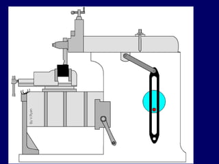
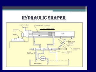
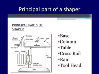
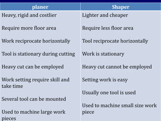
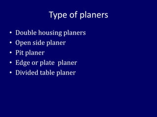
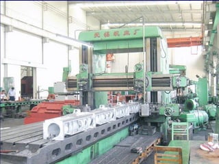
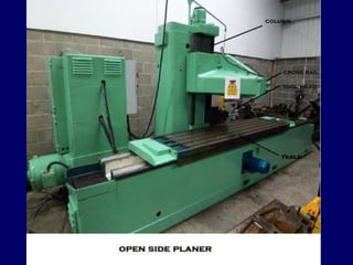
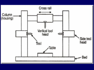
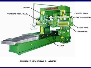
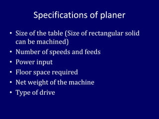
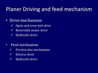
SHAPING MACHINE
ME 2123 Manufacturing Systems
• Reciprocating type machine
• It produces horizontal, vertical or incline
flat surfaces
• It cuts only during forward direction
Advantages of shaper
✓Can change from one job to another easily
✓Work can be held easily
✓Single point tools are inexpensive
✓Lower first cost
✓Cutting stroke has definite stop point
✓Cutting force is less
Classification of shaper machines
According to type of mechanism
Crank shaper
Geared shaper
Hydraulic shaper
Classification of shaper machines
According to position and travel of arm
Horizontal shaper
Vertical Shaper
Travelling head shaper
Classification of shaper machines
According to cutting stroke
Push cut shaper
Draw cut shaper
According to the design of table
Standard or plain shaper
Universal shaper
Principal part of a shaper
Specification of a shaper
• Max length of stroke
• Size of the table
• Max horizontal and vertical travel of table
• Max no of strokes per minutes
• Type of quick return mechanism
• Power of the drive motor
• Floor space required
• weight
Cutting tool used in shaper
Other tools used in shaper
• Try square
• Micrometer
• Surface gauge
• Sine bar
• Dial test indicator
Cutting speed, Feed and Depth
Cutting speed
average linear speed of the tool during cutting stroke
Feed
relative motion of work piece in a direction
perpendicular to tool stroke
Depth of cut
Thickness of material removed in a cut
• Cutting speed Vc m/min
• No of double stroke N cycle/min
• Length of ram stroke L mm
• Return stroke time/cutting stroke time
k
Vc =
NL(1+k)
1000
Cutting clearance c mm
Work piece length Lj mm
Width of work piece B mm
Feed f mm/d stroke
Total time to machine a surface
tm =
LB(1+k)
1000Vcf
• In terms of ram strokes N,
Machining time
tm = min
• Material Removal Rate
MRR = fDNL(1+k) mm3/min
B
fN
Calculate the machining time required for
machining a surface 450 x 650 mm on a
shaping machine, using the data given;
Cutting speed = 7.5 m/min
Return to cutting time ratio = 2 : 3
Feed = 2 mm/double stroke
The clearance at each end = 50 mm
• A cast iron surface 300mm long and 180mm
wide is to be machined on a shaper with
cutting to return ratio of 3:2. cutting speed ,
feed and clearance are 24.6 m/min, 2
mm/double stroke and 25 mm respectively.
The available ram strokes on the shaper are;
28, 40, 60 and 90 stroke/min. if the depth of
cut is 3.5 mm, determine;
a. Time required to machine the surface
b. Material removal rate
Advance manufacturing system and NDT
PLANING MACHINE
• Use in the production of flat surfaces on
work pieces too large or too heavy to hold in
a shaper
planer Shaper
Heavy, rigid and costlier
Require more floor area
Work reciprocate horizontally
Tool is stationary during cutting
Heavy cut can be employed
Work setting require skill and
take time
Several tool can be mounted
Used to machine large work
pieces
Lighter and cheaper
Require less floor area
Tool reciprocate horizontally
Work is stationary
Heavy cut cannot be employed
Setting work is easy
Usually one tool is used
Used to machine small size work
piece
Type of planers
• Double housing planers
• Open side planer
• Pit planer
• Edge or plate planer
• Divided table planer
Principal part of Planer
Specifications of planer
• Size of the table (Size of rectangular solid
can be machined)
• Number of speeds and feeds
• Power input
• Floor space required
• Net weight of the machine
• Type of drive
Planer Driving and feed mechanism
• Drive mechanism
✓ Open and cross belt drive
✓ Reversible motor drive
✓ Hydraulic drive
• Feed mechanism
✓ Friction disc mechanism
✓ Electric drive
✓ Hydraulic drive
Planer operations
• Planing horizontal surfaces
• Planing verticle surfaces
• Planing curved surfaces
• Planing slots and grooves
• Planing at an angle and machining dove-tails
• Planing a helix
• Gang or multiple Planing
Precautions for machines
• Lubrication is important to remove heat and
friction.
• Machines should be cleaned after use
• Chips should be removed using brush.
• T-slots, grooves, spindles sleeves, belts,
pulley should be cleaned.
• Machines should be lightly oiled to prevent
from rusting
Safety Precautions
• Do not support the work piece by hand – use
work holding device.
• Use brush to clean the chip
• No adjustments while the machine is operating
• Ensure for the cutting tools running straight
before starting the operation.
• Never place tools on the machine table
• Avoid loose clothing and protect the eyes.
• Ease the feed if drill breaks inside the work piece.

Introduction to Manufacturing Systemsshaping machine.pdf

  • 1.
    SHAPING MACHINE ME 2123Manufacturing Systems
  • 2.
    • Reciprocating typemachine • It produces horizontal, vertical or incline flat surfaces • It cuts only during forward direction
  • 3.
    Advantages of shaper ✓Canchange from one job to another easily ✓Work can be held easily ✓Single point tools are inexpensive ✓Lower first cost ✓Cutting stroke has definite stop point ✓Cutting force is less
  • 4.
    Classification of shapermachines According to type of mechanism Crank shaper Geared shaper Hydraulic shaper
  • 5.
    Classification of shapermachines According to position and travel of arm Horizontal shaper Vertical Shaper Travelling head shaper
  • 6.
    Classification of shapermachines According to cutting stroke Push cut shaper Draw cut shaper According to the design of table Standard or plain shaper Universal shaper
  • 9.
  • 10.
    Specification of ashaper • Max length of stroke • Size of the table • Max horizontal and vertical travel of table • Max no of strokes per minutes • Type of quick return mechanism • Power of the drive motor • Floor space required • weight
  • 11.
  • 12.
    Other tools usedin shaper • Try square • Micrometer • Surface gauge • Sine bar • Dial test indicator
  • 16.
    Cutting speed, Feedand Depth Cutting speed average linear speed of the tool during cutting stroke Feed relative motion of work piece in a direction perpendicular to tool stroke Depth of cut Thickness of material removed in a cut
  • 17.
    • Cutting speedVc m/min • No of double stroke N cycle/min • Length of ram stroke L mm • Return stroke time/cutting stroke time k Vc = NL(1+k) 1000
  • 18.
    Cutting clearance cmm Work piece length Lj mm Width of work piece B mm Feed f mm/d stroke Total time to machine a surface tm = LB(1+k) 1000Vcf
  • 19.
    • In termsof ram strokes N, Machining time tm = min • Material Removal Rate MRR = fDNL(1+k) mm3/min B fN
  • 20.
    Calculate the machiningtime required for machining a surface 450 x 650 mm on a shaping machine, using the data given; Cutting speed = 7.5 m/min Return to cutting time ratio = 2 : 3 Feed = 2 mm/double stroke The clearance at each end = 50 mm
  • 21.
    • A castiron surface 300mm long and 180mm wide is to be machined on a shaper with cutting to return ratio of 3:2. cutting speed , feed and clearance are 24.6 m/min, 2 mm/double stroke and 25 mm respectively. The available ram strokes on the shaper are; 28, 40, 60 and 90 stroke/min. if the depth of cut is 3.5 mm, determine; a. Time required to machine the surface b. Material removal rate
  • 22.
    Advance manufacturing systemand NDT PLANING MACHINE
  • 23.
    • Use inthe production of flat surfaces on work pieces too large or too heavy to hold in a shaper
  • 24.
    planer Shaper Heavy, rigidand costlier Require more floor area Work reciprocate horizontally Tool is stationary during cutting Heavy cut can be employed Work setting require skill and take time Several tool can be mounted Used to machine large work pieces Lighter and cheaper Require less floor area Tool reciprocate horizontally Work is stationary Heavy cut cannot be employed Setting work is easy Usually one tool is used Used to machine small size work piece
  • 25.
    Type of planers •Double housing planers • Open side planer • Pit planer • Edge or plate planer • Divided table planer
  • 31.
  • 34.
    Specifications of planer •Size of the table (Size of rectangular solid can be machined) • Number of speeds and feeds • Power input • Floor space required • Net weight of the machine • Type of drive
  • 35.
    Planer Driving andfeed mechanism • Drive mechanism ✓ Open and cross belt drive ✓ Reversible motor drive ✓ Hydraulic drive • Feed mechanism ✓ Friction disc mechanism ✓ Electric drive ✓ Hydraulic drive
  • 36.
    Planer operations • Planinghorizontal surfaces • Planing verticle surfaces • Planing curved surfaces • Planing slots and grooves • Planing at an angle and machining dove-tails • Planing a helix • Gang or multiple Planing
  • 37.
    Precautions for machines •Lubrication is important to remove heat and friction. • Machines should be cleaned after use • Chips should be removed using brush. • T-slots, grooves, spindles sleeves, belts, pulley should be cleaned. • Machines should be lightly oiled to prevent from rusting
  • 38.
    Safety Precautions • Donot support the work piece by hand – use work holding device. • Use brush to clean the chip • No adjustments while the machine is operating • Ensure for the cutting tools running straight before starting the operation. • Never place tools on the machine table • Avoid loose clothing and protect the eyes. • Ease the feed if drill breaks inside the work piece.