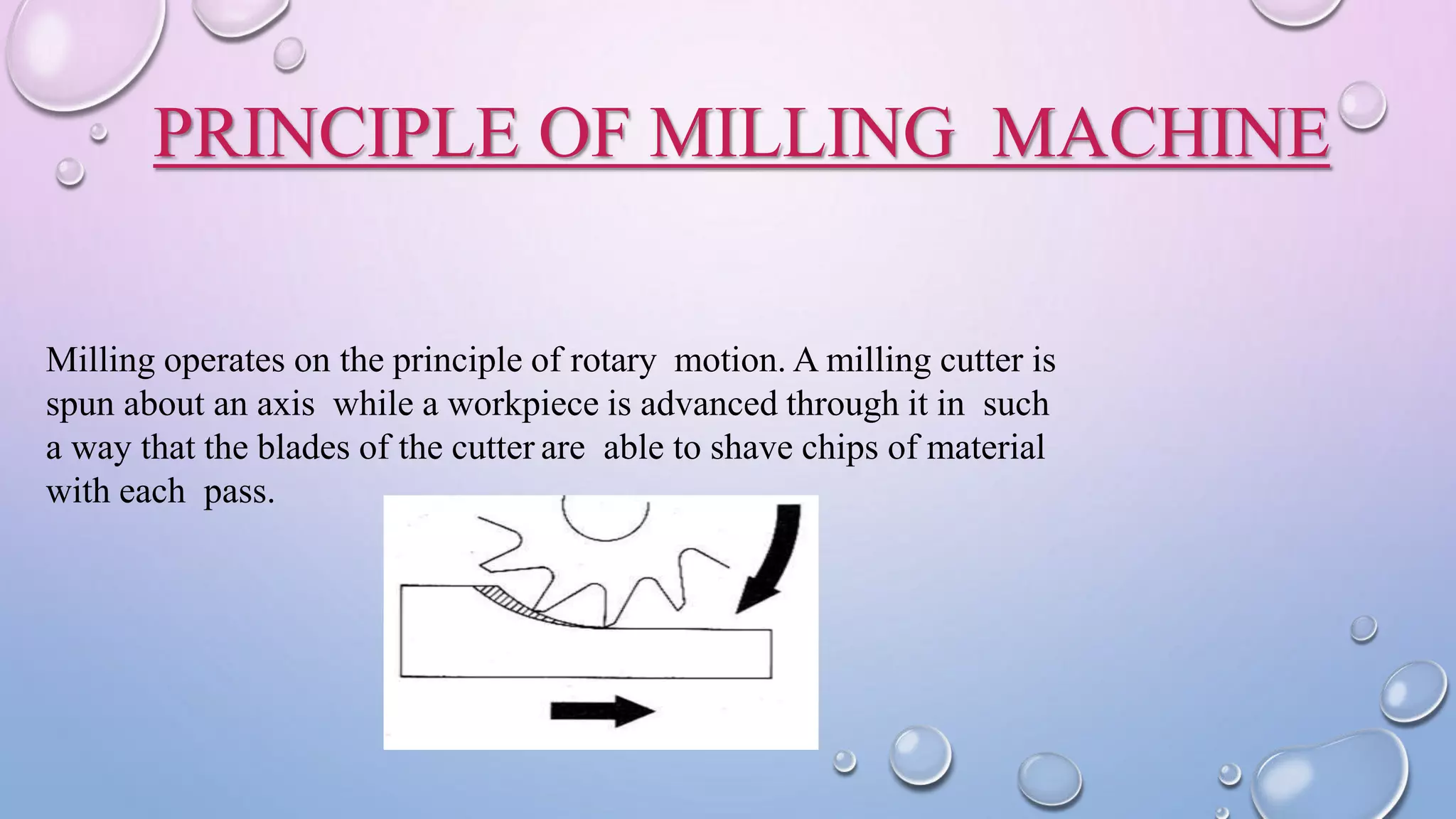
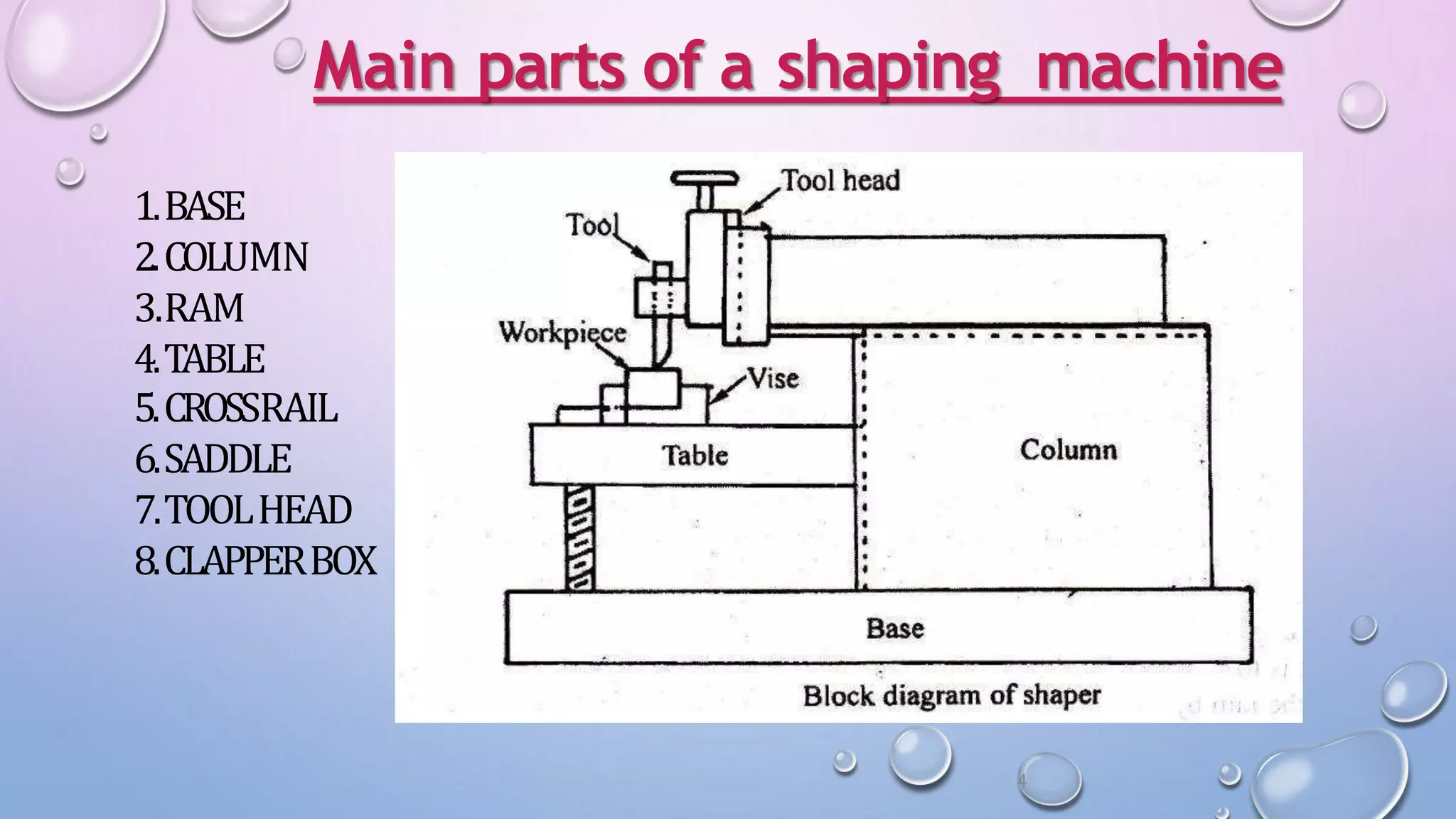
A
SEMINAR
ON
SHAPER, PLANER & MILLING MACHINE
SUBMITEDBY: SUBMITTEDTO:
SACHINKUMARSUNDRAM MANOJKUMAR
1713240079
WHAT IS MILLING?
Milling is the machining process of using
rotary cutters to remove material from a
workpiece advancing (or feeding) in a
direction at an angle with the axis of the
tool. It covers a wide variety of different
operations and machines, on scales from
small individual parts to large, heavy-duty
gang milling operations. It is one of the
most commonly used processes in industry
and machine shops today for machining
parts to precise sizes and shapes.
PRINCIPLE OF MILLING MACHINE
Milling operates on the principle of rotary motion. A milling cutter is
spun about an axis while a workpiece is advanced through it in such
a way that the blades of the cutter are able to shave chips of material
with each pass.
• Face milling
• End milling
• Keyway cutting
• Dovetail cutting
• T-slot
• circular slot
cutting
• Gear cutting
• Drilling
• Boring
• Jig boring
Variety of Operations
HORIZONTAL MILLING MACHINE
Horizontal milling machine.
1: base
2: column
3: knee
4 & 5: table (x-axis slide is integral)
6: overarm
7: arbor (attached to spindle)
A horizontal mill has the same sort of x–y table, but the cutters are mounted on a horizontal
arbor across the table. Many horizontal mills also feature a built-in rotary table that allows
milling at various angles; this feature is called a universal table.
VERTICAL MILLING
MACHINEVertical milling machine.
1: milling cutter
2: spindle
3: top slide or overarm
4: column
5: table
6: Y-axis slide
7: knee
8: base
In the vertical mill the spindle axis is vertically oriented. Milling cutters are
held in the spindle and rotate on its axis. The spindle can generally be
extended (or the table can be raised/lowered, giving the same effect), allowing
plunge cuts and drilling. There are two subcategories of vertical mills: the bed
mill and the turret mill.
Shaper
Machine
• Shaper is Machine tool which produces flat
surfaces in horizontal, vertical or inclined
planes depending upon the orientation of
the cutting tool.
Features:
• Single point cutting tool is used for
machining. Tool is clamped in the tool post
mounted on the ram ofthe machine.
• The ram reciprocates to and fro, tool cuts
the material in the forward stroke, No
cutting during returnstroke.
• Jobis held rigidly in avice.
SHAPERMachine
APPLICATIONDONEUSINGASHAPER
• Machining Horizontal Surfaces
• Machining Vertical Surfaces
• MachiningAngular Surfaces
• Cutting Slots, Grooves & Keyways
• Machining irregular surfaces
• Machining Splines/ Cutting Gears
4
Main parts of a shaping machine
1.BASE
2.COLUMN
3.RAM
4.TABLE
5.CROSSRAIL
6.SADDLE
7.TOOLHEAD
8.CLAPPERBOX
1.Position of ramtravel
• Horizontal Shaper- Ramholding the cutting tool moves Inhorizontal plane
• Vertical Shaper-The cutting tool moves in verticalplane
• Traveling head Shaper-Cutting tool reciprocates & movescrosswise
simultaneously
2 Acc.to Cutting Strokeaction
a) PushTypeShaper- Standard Shaper.
• Metal is removed when the ram moves away fromcolumn
• Most common type used inpractice
• Unless otherwise specified, the term shaper refers toPushtype Shaper
b) Draw TypeShaper
• Metal is removed when the tool is drawn towards the column
• Allows heavier cuts to bemade
• Lessvibration during cutting
CLASSIFICATION
3 Acc.to DrivingMechanism:
a) Cranktype
b) Gearedtype
- Driving mechanism is by crank & gear
- Driven by Rack& Pinionmechanism
c) Hydraulic Shaper- Driven by oil pressure developed by apump,
which is run by an electricmotor
4 Acc.to the TableDesign:
a) Standard shaper- Work Tablecan be
moved 1.Vertically & 2.Horizontally
b) Universal Shaper-Tablecan be moved
1. Horizontally 2. Vertically 3. Swivelled &4. Tilted
Thisis mostly used in ToolRooms
MECHANISM
Crankand slotted lever Quick return mechanism
 Theram of the shapermay be
driven by mechanical drive or
hydraulicdrive.
 Sincecutting take place only
once in adouble stroke and the
other stroke is idle, the shaper
ram should be provided with a
quickreturn feature.
 Mechanically driven shaper
make use of the slotted arm
quick return mechanism.
Planer
Machine
PLANER
• Planer is a machine with a cutting tool that makes
repeated horizontal strokes acrossthe surface of a
workpiece: used to cut flat surfacesinto metal
CLASSIFICATIONOFPLANER
Planers are generalley divided into 5types:
• Double Housing Planer
• OpenSidePlaner
• EdgeType Planer
• Divide TablePlaner
• Pit TypePlaner
DOUBLEHOUSING
PLANER• It is the most common type of planer. It consists of mainly a
massivebed on which the worktable reciprocates, and two
vertical columns or housing, one on eachside of the bed.
Eachcolumn carries atool head that canbe slide up and
down on the column.
• Acrossrail fitted between the two columns may carry one or
two tool heads that canslide horizontally on the crossrail.
All the tool heads canbe clamped in position, and canbe
used collectively or individually depending on the
requirements.
OPENSIDEPLANER
• Open side planer consists of only one vertical column or housing
on which the crossrail ismounted.
• Thecolumn and the crossrail carry single and double tool
heads respectively. Thistype of machine permitsmachining of
wide work pieces.
EDGETYPEPLANER
• Thistype of machine is used for machining the edgesof heavy
work pieces.Thework piece is clamped on the bed and the side
mounted carriage supporting the cutting tool is reciprocated
along the edgeof the work piece. Cutting cantake place during
both directions of carriagetravel.
DIVIDE TYPEPLANER
• It is also called tandem planer and consists of two
worktables, which may be reciprocated together or
separately. It is quite well known that, mounting and setting
of workpieces on the worktable consumesmore time
thereby restricting the machine for continuous mass
production applications.
• In suchcases,divided table planer canbe used, where in,
one worktable canbe used for setting up anewworkpiece,
while the second worktable carrying workpiece is being
machined. Thetwo tables canbe joined together to hold
large workpieces.
PITTYPE
PLANER• Apit type planer differs from other planer in the sensethat,
the table and the work piece resting on it remain stationary
and the tool reciprocates acrossthe work surface. Thistype
of machine is preferred for very large work, where the
weight of the work piece and the tool required table would
makereciprocating movement difficult. Thejob is either
mounted on astationary table, or on the floor inside apit,
and hence the name pit type planer. Oneor two tool heads
can be mounted on the crossrail and two side tool posts the
housings, if required. Theentire unit travels along the
horizontal waysand fro and, thus the tool moves past the
work surface duringoperation.
PLANINGMACHINEPARTS
• The main parts of
planner are:
• Bed
•Table
•Column
•Cross rail
•Tool head
ANY
QUESTIONS…?
shaper machine, planer machines, and milling machine ppt

shaper machine, planer machines, and milling machine ppt

  • 1.
    A SEMINAR ON SHAPER, PLANER &MILLING MACHINE SUBMITEDBY: SUBMITTEDTO: SACHINKUMARSUNDRAM MANOJKUMAR 1713240079
  • 3.
    WHAT IS MILLING? Millingis the machining process of using rotary cutters to remove material from a workpiece advancing (or feeding) in a direction at an angle with the axis of the tool. It covers a wide variety of different operations and machines, on scales from small individual parts to large, heavy-duty gang milling operations. It is one of the most commonly used processes in industry and machine shops today for machining parts to precise sizes and shapes.
  • 4.
    PRINCIPLE OF MILLINGMACHINE Milling operates on the principle of rotary motion. A milling cutter is spun about an axis while a workpiece is advanced through it in such a way that the blades of the cutter are able to shave chips of material with each pass.
  • 5.
    • Face milling •End milling • Keyway cutting • Dovetail cutting • T-slot • circular slot cutting • Gear cutting • Drilling • Boring • Jig boring Variety of Operations
  • 6.
    HORIZONTAL MILLING MACHINE Horizontalmilling machine. 1: base 2: column 3: knee 4 & 5: table (x-axis slide is integral) 6: overarm 7: arbor (attached to spindle) A horizontal mill has the same sort of x–y table, but the cutters are mounted on a horizontal arbor across the table. Many horizontal mills also feature a built-in rotary table that allows milling at various angles; this feature is called a universal table.
  • 8.
    VERTICAL MILLING MACHINEVertical millingmachine. 1: milling cutter 2: spindle 3: top slide or overarm 4: column 5: table 6: Y-axis slide 7: knee 8: base In the vertical mill the spindle axis is vertically oriented. Milling cutters are held in the spindle and rotate on its axis. The spindle can generally be extended (or the table can be raised/lowered, giving the same effect), allowing plunge cuts and drilling. There are two subcategories of vertical mills: the bed mill and the turret mill.
  • 10.
  • 11.
    • Shaper isMachine tool which produces flat surfaces in horizontal, vertical or inclined planes depending upon the orientation of the cutting tool. Features: • Single point cutting tool is used for machining. Tool is clamped in the tool post mounted on the ram ofthe machine. • The ram reciprocates to and fro, tool cuts the material in the forward stroke, No cutting during returnstroke. • Jobis held rigidly in avice. SHAPERMachine
  • 12.
    APPLICATIONDONEUSINGASHAPER • Machining HorizontalSurfaces • Machining Vertical Surfaces • MachiningAngular Surfaces • Cutting Slots, Grooves & Keyways • Machining irregular surfaces • Machining Splines/ Cutting Gears
  • 13.
    4 Main parts ofa shaping machine 1.BASE 2.COLUMN 3.RAM 4.TABLE 5.CROSSRAIL 6.SADDLE 7.TOOLHEAD 8.CLAPPERBOX
  • 14.
    1.Position of ramtravel •Horizontal Shaper- Ramholding the cutting tool moves Inhorizontal plane • Vertical Shaper-The cutting tool moves in verticalplane • Traveling head Shaper-Cutting tool reciprocates & movescrosswise simultaneously 2 Acc.to Cutting Strokeaction a) PushTypeShaper- Standard Shaper. • Metal is removed when the ram moves away fromcolumn • Most common type used inpractice • Unless otherwise specified, the term shaper refers toPushtype Shaper b) Draw TypeShaper • Metal is removed when the tool is drawn towards the column • Allows heavier cuts to bemade • Lessvibration during cutting CLASSIFICATION
  • 15.
    3 Acc.to DrivingMechanism: a)Cranktype b) Gearedtype - Driving mechanism is by crank & gear - Driven by Rack& Pinionmechanism c) Hydraulic Shaper- Driven by oil pressure developed by apump, which is run by an electricmotor 4 Acc.to the TableDesign: a) Standard shaper- Work Tablecan be moved 1.Vertically & 2.Horizontally b) Universal Shaper-Tablecan be moved 1. Horizontally 2. Vertically 3. Swivelled &4. Tilted Thisis mostly used in ToolRooms
  • 16.
    MECHANISM Crankand slotted leverQuick return mechanism  Theram of the shapermay be driven by mechanical drive or hydraulicdrive.  Sincecutting take place only once in adouble stroke and the other stroke is idle, the shaper ram should be provided with a quickreturn feature.  Mechanically driven shaper make use of the slotted arm quick return mechanism.
  • 17.
  • 18.
    PLANER • Planer isa machine with a cutting tool that makes repeated horizontal strokes acrossthe surface of a workpiece: used to cut flat surfacesinto metal
  • 19.
    CLASSIFICATIONOFPLANER Planers are generalleydivided into 5types: • Double Housing Planer • OpenSidePlaner • EdgeType Planer • Divide TablePlaner • Pit TypePlaner
  • 20.
    DOUBLEHOUSING PLANER• It isthe most common type of planer. It consists of mainly a massivebed on which the worktable reciprocates, and two vertical columns or housing, one on eachside of the bed. Eachcolumn carries atool head that canbe slide up and down on the column. • Acrossrail fitted between the two columns may carry one or two tool heads that canslide horizontally on the crossrail. All the tool heads canbe clamped in position, and canbe used collectively or individually depending on the requirements.
  • 21.
    OPENSIDEPLANER • Open sideplaner consists of only one vertical column or housing on which the crossrail ismounted. • Thecolumn and the crossrail carry single and double tool heads respectively. Thistype of machine permitsmachining of wide work pieces. EDGETYPEPLANER • Thistype of machine is used for machining the edgesof heavy work pieces.Thework piece is clamped on the bed and the side mounted carriage supporting the cutting tool is reciprocated along the edgeof the work piece. Cutting cantake place during both directions of carriagetravel.
  • 22.
    DIVIDE TYPEPLANER • Itis also called tandem planer and consists of two worktables, which may be reciprocated together or separately. It is quite well known that, mounting and setting of workpieces on the worktable consumesmore time thereby restricting the machine for continuous mass production applications. • In suchcases,divided table planer canbe used, where in, one worktable canbe used for setting up anewworkpiece, while the second worktable carrying workpiece is being machined. Thetwo tables canbe joined together to hold large workpieces.
  • 23.
    PITTYPE PLANER• Apit typeplaner differs from other planer in the sensethat, the table and the work piece resting on it remain stationary and the tool reciprocates acrossthe work surface. Thistype of machine is preferred for very large work, where the weight of the work piece and the tool required table would makereciprocating movement difficult. Thejob is either mounted on astationary table, or on the floor inside apit, and hence the name pit type planer. Oneor two tool heads can be mounted on the crossrail and two side tool posts the housings, if required. Theentire unit travels along the horizontal waysand fro and, thus the tool moves past the work surface duringoperation.
  • 24.
    PLANINGMACHINEPARTS • The mainparts of planner are: • Bed •Table •Column •Cross rail •Tool head
  • 25.