Download as PDF, PPTX


![MID-TERM REVIEW, 2017
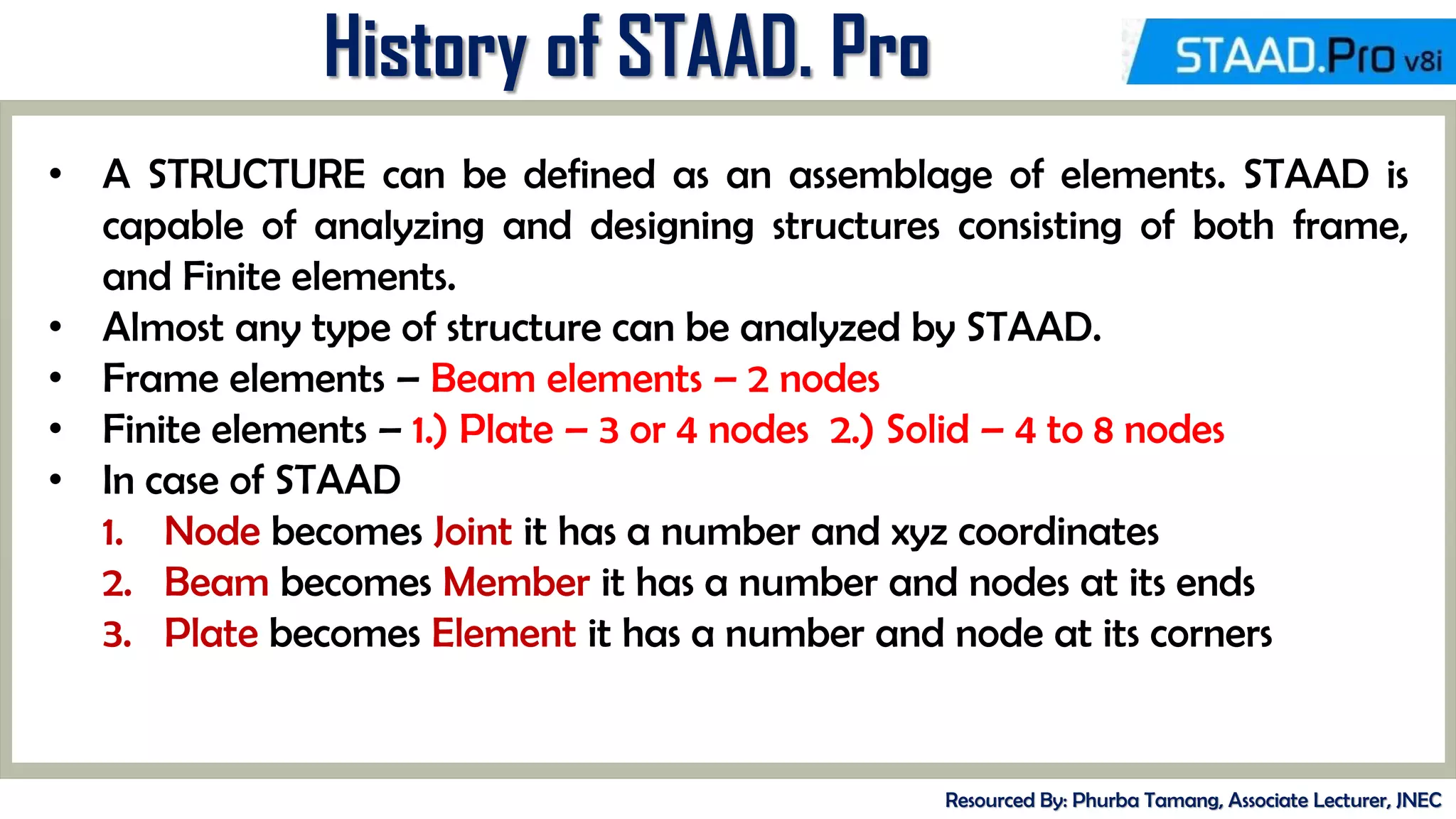
Types of Structure
Resourced By: Phurba Tamang, Associate Lecturer, JNEC
• A TRUSS structure consists of truss members which can have only axial
member forces and no bending in the members.
• A PLANE structure is bound by a global X-Y coordinate system with loads
in the same plane.
• A SPACE structure, which is a three dimensional framed structure with
loads applied in any plane, is the most general.
• A FLOOR structure is a two or three dimensional structure having no horizontal (global
X or Z) movement of the structure [FX, FZ & MY are restrained at every joint]. The
floor framing (in global X-Z plane) of a building is an ideal example of a FLOOR
structure. Columns can also be modelled with the floor in a FLOOR structure as long as
the structure has no horizontal loading. If there is any horizontal load, it must be
analyzed as a SPACE structure.](https://image.slidesharecdn.com/staadhandout-230906132113-bfc9029c/75/Introduction-to-StaadPro-7-2048.jpg)

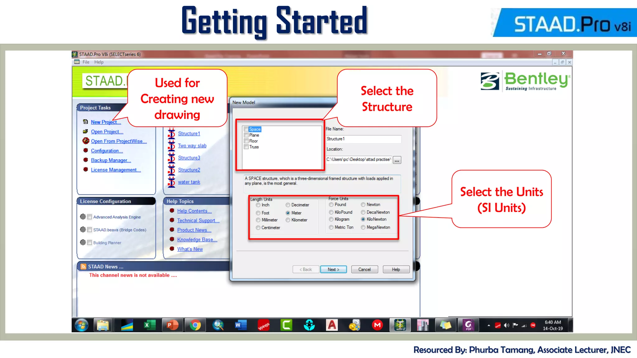
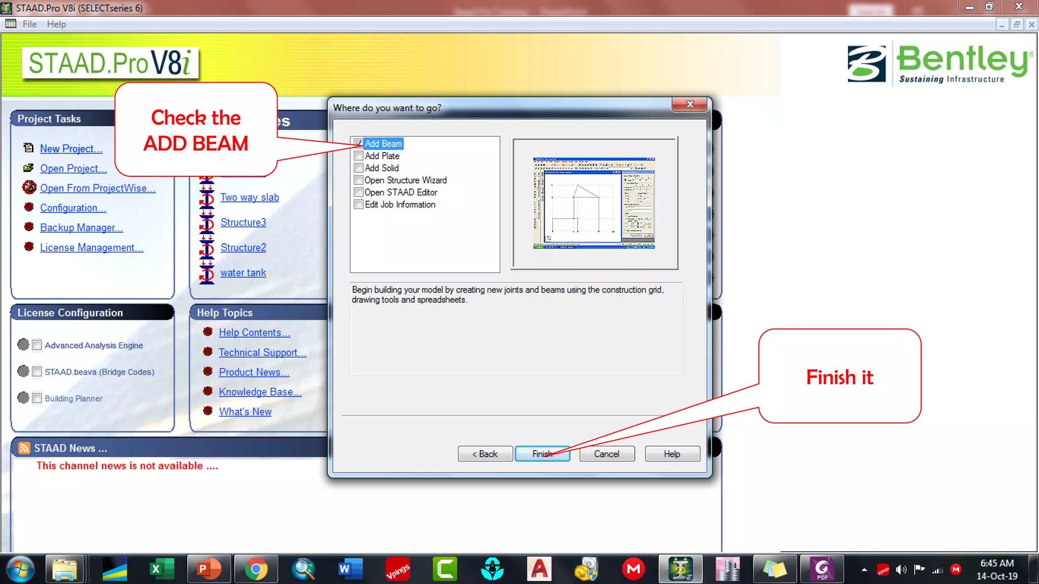
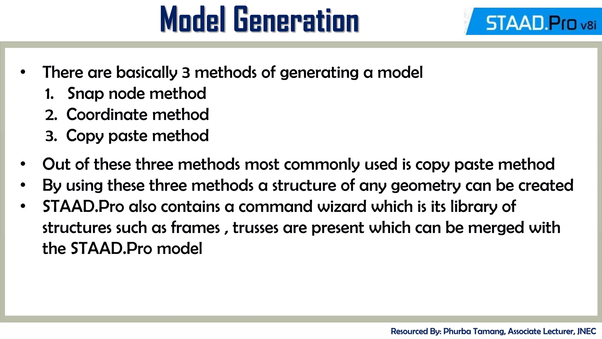


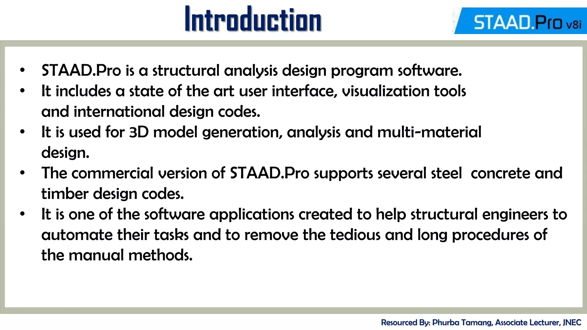
This document provides an overview of the basic STAAD.Pro training presented by Phurba Tamang, an associate lecturer at the Jigme Namgyel Engineering College. It introduces STAAD.Pro as a structural analysis and design software and covers topics like the history and versions of STAAD.Pro, getting started with the software interface, model generation techniques, defining structural properties and loads, analyzing structures, and references to design codes. The document also includes some example exercises demonstrating how to model and analyze simple structures in STAAD.Pro.


![project [Autobots].pptxhfhjbjkkijhhhhhhhhhhhyy](https://cdn.slidesharecdn.com/ss_thumbnails/projectautobots-250122061534-039dfed1-thumbnail.jpg?width=640&height=640&fit=bounds)


