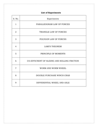
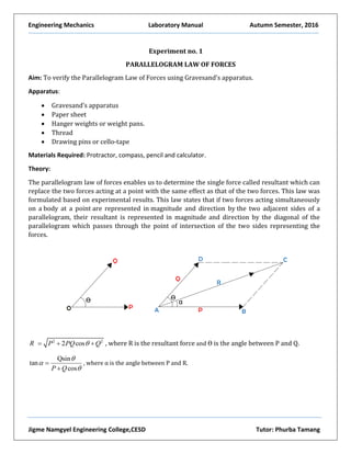
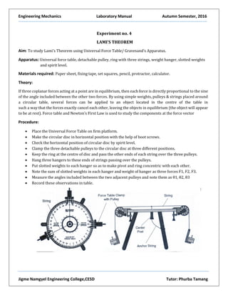
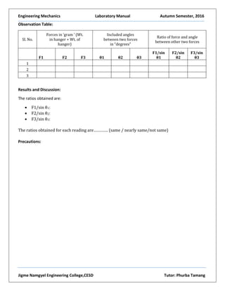
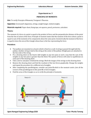
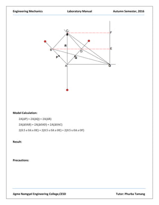
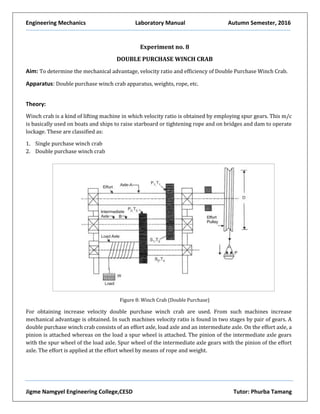
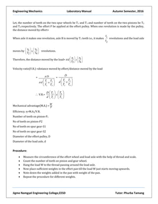
Compiled By: Phurba Tamang, Asst. Lecturer in CESD
Royal University of Bhutan
Jigme Namgyel Engineering College
Civil Engineering and Surveying Department
ENIGNEERING MECHANICS
Laboratory Instruction Manual
Semester-I
List of Experiments
S. No. Experiments
1 PARALLEOGRAM LAW OF FORCES
2 TRIANGLE LAW OF FORCES
3 POLYGON LAW OF FORCES
4 LAMI’S THEOREM
5 PRINCIPLE OF MOMENTS
6 CO-EFFICNENT OF SLIDING AND ROLLING FRICTION
7 WORM AND WORM WHEEL
8 DOUBLE PURCHASE WINCH CRAB
9 DIFFERENTIAL WHEEL AND AXLE
Engineering Mechanics Laboratory Manual Autumn Semester, 2016
Jigme Namgyel Engineering College,CESD Tutor: Phurba Tamang
Experiment no. 1
PARALLELOGRAM LAW OF FORCES
Aim: To verify the Parallelogram Law of Forces using Gravesand’s apparatus.
Apparatus:
 Gravesand’s apparatus
 Paper sheet
 Hanger weights or weight pans.
 Thread
 Drawing pins or cello-tape
Materials Required: Protractor, compass, pencil and calculator.
Theory:
The parallelogram law of forces enables us to determine the single force called resultant which can
replace the two forces acting at a point with the same effect as that of the two forces. This law was
formulated based on experimental results. This law states that if two forces acting simultaneously
on a body at a point are represented in magnitude and direction by the two adjacent sides of a
parallelogram, their resultant is represented in magnitude and direction by the diagonal of the
parallelogram which passes through the point of intersection of the two sides representing the
forces.
2 2
2 cosR P PQ Q   , where R is the resultant force and Ɵ is the angle between P and Q.
Qsin
tan
cosP Q





, where α is the angle between P and R.
Engineering Mechanics Laboratory Manual Autumn Semester, 2016
Jigme Namgyel Engineering College,CESD Tutor: Phurba Tamang
Procedure:
 Two pulleys are mounted on a board, which is fixed on a wall. A string is passed through both the
pulleys. Another string is tied to this string at the center of the pulleys. Weight pans are attached
to the two ends of the string.
 Fix a drawing sheet on the board.
 Add weights in any two pans in such a way that the sum of the weights in any two pans is greater
than the third. The system of forces will come to equilibrium on some part of the drawing sheet.
 Record the weights.
 Mark the position of strings on the drawing sheet with a pencil. Remove the drawing sheet and
find the resultant of the two forces graphically and analytically.
 Change the weights and repeat the procedure for each set of weights.
 The recorded weights are taken as the experimental values
Figure 1-1: Experimental setup for Parallelogram Law of Forces
Engineering Mechanics Laboratory Manual Autumn Semester, 2016
Jigme Namgyel Engineering College,CESD Tutor: Phurba Tamang
Model Calculations:
2 2
2 cosR P PQ Q   and
Qsin
tan
cosP Q





Observation table:
Force (grams)
Resultant (R)
Graphically
Angle
between
P and Q
Resultant
angle (α)
between
P and R
Angle (α)
Analytically
between
P and R
Resultant (R)
analyticallySet up P Q R
I 150 150 150 2.95 x 50 =
147.5
119˚ 60˚ 59.5˚ 152.25
II
III
Results and Discussion:
 Experimental value of Resultant, R:
 Analytical value of Resultant, R:
 Graphical Value of Resultant, R:
Percentage (%) error of Resultant in Experimental and Analytical value:
%, error:
𝐸𝑥𝑝𝑒𝑟𝑖𝑚𝑒𝑛𝑡𝑎𝑙 𝑣𝑎𝑙𝑢𝑒−𝐴𝑛𝑎𝑙𝑦𝑡𝑖𝑐𝑎𝑙 𝑣𝑎𝑙𝑢𝑒
𝐸𝑥𝑝𝑒𝑟𝑖𝑚𝑒𝑛𝑡𝑎𝑙 𝑣𝑎𝑙𝑢𝑒
x 100
Percentage (%) error of Resultant in Experimental and Graphical value:
%, error:
𝐸𝑥𝑝𝑒𝑟𝑖𝑚𝑒𝑛𝑡𝑎𝑙 𝑣𝑎𝑙𝑢𝑒−𝐺𝑟𝑎𝑝ℎ𝑖𝑐𝑎𝑙 𝑣𝑎𝑙𝑢𝑒
𝐸𝑥𝑝𝑒𝑟𝑖𝑚𝑒𝑛𝑡𝑎𝑙 𝑣𝑎𝑙𝑢𝑒
x 100
Precautions:
Engineering Mechanics Laboratory Manual Autumn Semester, 2016
Jigme Namgyel Engineering College,CESD Tutor: Phurba Tamang
Experiment no. 2
TRIANGLE LAW OF FORCES
Aim: To verify the Triangle Law of Forces using Universal Force Table.
Apparatus:
 Universal Force table
 Paper sheet
 Hanger weights or weight pans.
 Thread
 Central Ring.
Materials Required: Protractor, compass, scale, pencil, set squares and calculator.
Theory:
This law states that if two forces acting simultaneously on a body are represented by sides of a
triangle taken in order, then their resultant is represented by the closing side of the triangle, taken
in opposite order. In figure below, forces P and Q are represented in magnitude (to suitable scale)
and direction by AB and BC. According to this law, the closing line of the triangle ABC i.e., AC
represents the resultant R.
Engineering Mechanics Laboratory Manual Autumn Semester, 2016
Jigme Namgyel Engineering College,CESD Tutor: Phurba Tamang
Procedure:
 Clamp the pulleys to the graduated disc of Force Table and make it horizontal by adjusting
the screws provided at its base. (Note: Adjust the position of one of the pulleys at an
angle of zero degrees at the Force Table)
 Use the bubble level to check if the circular platform is horizontal. Use the leveling screws,
if necessary, to make the necessary adjustments.
 Adjust the other two pulleys at derived angle from pulley one.
 Tie each of the three strings to the circumference of the small ring provided with the
apparatus. The other ends of the strings are to be attached to the weight hanger which are
to carry small slotted weights, hanging over the pulley as shown in figure: 1-1.
Figure 1-1: Universal Force Table
 Add weights on one of the weight hangers and take it as the experimental value of weight.
 Put small weights on the weight hangers in such a manner that the ring is positioned
symmetrically around the axle and it does not touch the axle of the apparatus.
 Note the angles made by the strings and corresponding weights of the weight hangers.
 Draw the space diagram and verify the Triangle Law of Forces.
Engineering Mechanics Laboratory Manual Autumn Semester, 2016
Jigme Namgyel Engineering College,CESD Tutor: Phurba Tamang
Observation table:
Force (grams) Magnitude of R from
Triangle (Graphical
value)
Angle between
P and Q
Resultant angle (α)
Between P and R
% error in
Resultant (R)
Set up P Q R
I 150 150 200 2.95 x 50 = 147.5 60˚ 60˚ 2
II
III
Results and Discussion:
 Experimental value of Resultant, R:
 Graphical Value of Resultant, R:
Percentage (%) error of Resultant in Experimental and Graphical value:
%, error:
𝐸𝑥𝑝𝑒𝑟𝑖𝑚𝑒𝑛𝑡𝑎𝑙 𝑣𝑎𝑙𝑢𝑒−𝐺𝑟𝑎𝑝ℎ𝑖𝑐𝑎𝑙 𝑣𝑎𝑙𝑢𝑒
𝐸𝑥𝑝𝑒𝑟𝑖𝑚𝑒𝑛𝑡𝑎𝑙 𝑣𝑎𝑙𝑢𝑒
x 100
Precautions:
Engineering Mechanics Laboratory Manual Autumn Semester, 2016
Jigme Namgyel Engineering College,CESD Tutor: Phurba Tamang
Experiment no. 3
POLYGON LAW OF FORCES
Aim: To verify the law of polygon of forces using Universal Force Table.
Apparatus: Universal force table apparatus, pulleys, a ring with four or five strings, weights.
Materials required: Paper sheet, fixing tape, set squares, pencil, protractor, calculator.
Theory:
The Law of Polygon of forces states that “if a number of coplanar concurrent forces acting on a body be
represented in magnitude and direction by the sides of a polygon, taken in order, then their resultant is
represented in magnitude and direction by the closing side of the polygon, taken in opposite order.
Procedure:
 Clamp the pulleys to the graduated disc of the force table and make it horizontal by adjusting the
screws provided at its base. (Note: Adjust the position of one of the pulleys at an angle of zero
degrees at the Force Table)
 Use the bubble level to check if the circular platform is horizontal. Use the leveling screws, if
necessary, to make the necessary adjustments.
 Tie each of the strings to the circumference of the small ring provided with the apparatus and place
it around the axle of the apparatus. The other ends of the strings are to be attached to the weight
hangers which are to carry small slotted weights, hanging over the pulleys as shown in figure: 1-1.
 Put some small weights on the weight hangers in such a manner that the ring is positioned
symmetrically around the axle and it does not touch the axle of the apparatus.
 Note the position of any one string on the disc and then find the angles between all the strings as θ1,
θ2, θ3, θ4 and θ5.
 Record corresponding weights of the weight hangers.
 Draw the space diagram of the forces W1=P, W2=Q, W3=R, W4=S and W5=T acting on the ring as shown
in fig. 1-2.
 Draw the force diagram abcde as shown and verify that the polygon abcde is completed. If the last
force i.e. W5=T represented by the side ea fails short or greater than the side which would complete
the polygon, then find the percentage error between the last observed force T and ea required to
complete the polygon as given in the observation chart.
 Similarly measure the angles a’ab which should be equal to θ5 and if they are different then find the
percentage error between these angles as given in the observation chart.
Engineering Mechanics Laboratory Manual Autumn Semester, 2016
Jigme Namgyel Engineering College,CESD Tutor: Phurba Tamang
Figure 1-1: Universal Forces Table
Figure 3-2: Force diagram Figure 2-3: Vector diagram
T
Engineering Mechanics Laboratory Manual Autumn Semester, 2016
Jigme Namgyel Engineering College,CESD Tutor: Phurba Tamang
Observation Table:
Results and Discussion:
 Experimental value of T
 Graphical value of T
 % error in force, T
 % error in angles a’ab & θ5
Precautions:
Set
up
Weight (grams) Angle
Last force,T
(Observed)
Magnitude of T
from Polygon
(Graphical)
% error in
force, T
% error in
angles
a’ab & θ5
P Q R S θ1 θ2 θ3 θ4
Engineering Mechanics Laboratory Manual Autumn Semester, 2016
Jigme Namgyel Engineering College,CESD Tutor: Phurba Tamang
Experiment no. 4
LAMI’S THEOREM
Aim: To study Lami’s Theorem using Universal Force Table/ Gravesand’s Apparatus.
Apparatus: Universal force table, detachable pulley, ring with three strings, weight hanger, slotted weights
and spirit level.
Materials required: Paper sheet, fixing tape, set squares, pencil, protractor, calculator.
Theory:
If three coplanar forces acting at a point are in equilibrium, then each force is directly proportional to the sine
of the angle included between the other two forces. By using simple weights, pulleys & strings placed around
a circular table, several forces can be applied to an object located in the centre of the table in
such a way that the forces exactly cancel each other, leaving the objects in equilibrium (the object will appear
to be at rest). Force table and Newton’s First Law is used to study the components at the force vector
Procedure:
 Place the Universal Force Table on firm platform.
 Make the circular disc in horizontal position with the help of boot screws.
 Check the horizontal position of circular disc by spirit level.
 Clamp the three detachable pulleys to the circular disc at three different positions.
 Keep the ring at the centre of disc and pass the other ends of each string over the three pulleys.
 Hang three hangers to these ends of strings passing over the pulleys.
 Put slotted weights to each hanger so as to make pivot and ring concentric with each other.
 Note the sum of slotted weights in each hanger and weight of hanger as three forces F1, F2, F3.
 Measure the angles included between the two adjacent pulleys and note them as θ1, θ2, θ3
 Record these observations in table.
Engineering Mechanics Laboratory Manual Autumn Semester, 2016
Jigme Namgyel Engineering College,CESD Tutor: Phurba Tamang
Observation Table:
Sl. No.
Forces in ‘gram ’ (Wt.
in hanger + Wt. of
hanger)
Included angles
between two forces
in “degrees”
Ratio of force and angle
between other two forces
F1 F2 F3 θ1 θ2 θ3
F1/sin
θ1
F2/sin
θ2
F3/sin
θ3
1
2
3
Results and Discussion:
The ratios obtained are:
 F1/sin θ1:
 F2/sin θ2:
 F3/sin θ3:
The ratios obtained for each reading are…………. (same / nearly same/not same)
Precautions:
Engineering Mechanics Laboratory Manual Autumn Semester, 2016
Jigme Namgyel Engineering College,CESD Tutor: Phurba Tamang
Experiment no. 5
PRINCIPLE OF MOMENTS
Aim: To verify Principle of Moments/ Varignon’s Theorem.
Apparatus: Gravesand’s Apparatus, strings, weight hanger, slotted weights.
Materials required: Paper sheet, fixing tape, set squares, pencil, protractor, calculator.
Theory:
The moment of a force at a point is equal to the product of force and the perpendicular distance of the point
from the line of action of the force. Principle of moment states that the moment of the force about a point is
equal to sum of the moments of its components about the same point. Geometrically the moment of the force
is equal to twice the area of the triangle whose base is the line representing the force.
Procedure:
 Two pulleys are mounted on a board, which is fixed on a wall. A string is passed through both the
pulleys. Another string is tied to this string at the center of the pulleys. Weight pans are attached to
the two ends of the string.
 Fix a drawing sheet on the board. Add weights in any two pans in such a way that the sum of the
weights in any two pans is greater than the third. The system of forces will come to equilibrium on
some part of the drawing sheet.
 Take a mirror and place it behind the strings. Mark the images of the strings on the drawing sheet.
 Remove the drawing sheet and find the resultant of the two forces graphically. Change the weights
and repeat the procedure for a different set of weights.
 After completing the parallelogram, consider any point O which is the moment centre. Join all the
corners of the parallelogram to this point O, to form triangles.
 Find the areas of the triangles so as to verify the principle of moments.
Engineering Mechanics Laboratory Manual Autumn Semester, 2016
Jigme Namgyel Engineering College,CESD Tutor: Phurba Tamang
Model Calculation:
2A(ΔP) + 2A(ΔQ) = 2A(ΔR)
2A(ΔOAB) + 2A(ΔOAD) = 2A(ΔOAC)
2(0.5 x OA x OE) + 2(0.5 x OA x OE) = 2(0.5 x OA x OF)
Result:
Precautions:
Engineering Mechanics Laboratory Manual Autumn Semester, 2016
Jigme Namgyel Engineering College,CESD Tutor: Phurba Tamang
Experiment no. 6
COEFFICIENT OF SLIDING AND ROLLING FRICTION
Aim: To determine the co-efficient of sliding and rolling friction using Friction Sliding Apparatus.
Apparatus: Friction Sliding Apparatus, strings, weighing pan, slotted weights, thread, glass, roller object,
objects with varying surfaces (Brass, wood, leather, aluminum, etc.).
Materials required: Paper sheet, calculator, pencil, spirit level, spring balance.
Theory:
When one body moves, or tends to move tangentially over the surface of the other, it experiences a force which
opposes the motion. This force acting opposite to the direction of motion is called friction. Sliding
friction (kinetic friction) is the force of friction between two surfaces which are rubbing against each other.
Sliding friction is a consequence of having small protrusions on a surface. Whenever the two surfaces are
moving against each other, the protrusions interlock and work needs to be done to keep the objects in motion.
Rolling friction occurs when the surface of one body is rolling against the surface of another body. The origin
of this force is the deformations that occur on the surfaces as rolling occurs. Rolling friction is always
considered to be less than the sliding friction.
Co-efficient of friction: It is the ratio of limiting frictional force (F) to the normal reaction (N). µ =
Free Body Diagram
Engineering Mechanics Laboratory Manual Autumn Semester, 2016
Jigme Namgyel Engineering College,CESD Tutor: Phurba Tamang
Where W: weight of the object, N: Normal Reaction, P: External Effort, F: Limiting Frictional Force
Since, ∑H=0, P=F, which means External Effort/Force is equal to Limiting Friction.
Similarly, when ∑V=0, W=N, which means Weight of the object is equal to the Normal Reaction.
Procedure:
 Set the plane horizontally either with the help of a spirit level or by making the inclination of the
plane to zero degrees.
 Take a string with a pan attached to it and pass the string over the pully fixed to the plane such a way
that the string is parallel to the plane.
 Attached to the other end of the string, is a wooden block kept on the plane.
 Place the weights in the pan and record the weights in the pan. Record the weight at which the wooden
block just starts sliding when tapping the table.
 Record them in the observation table.
 Find the co-efficient of friction for different values of total weight W and total effort P.
 Repeat the procedure by placing different weights on the wooden block for three or more readings.
 Find the average co-efficient of friction, µ for the given pair of surfaces.
 Plot a graph taking normal reaction N, along X-axis and limiting friction F, along Y-axis. The graph will
be a straight line sloping upwards.
 The coefficient of friction is also calculated by measuring the slope of the graph.
 Carry out same procedures to determine the coefficient of rolling friction.
Observation Table:
Note: Take the weights in gram
The given pair of surfaces are: 1) …………………. 2) ………………
Weight of
block (W1)
Weight on
block (W2)
Total Weight
W=W1+W2
(W=N)
Weight of
Pan (P1)
Weight of
Pan(P2)
Total Effort
P=P1+P2
(P=F)
µ =
50 200 250 31 20 51 0.2
Engineering Mechanics Laboratory Manual Autumn Semester, 2016
Jigme Namgyel Engineering College,CESD Tutor: Phurba Tamang
Results and Discussion:
The average co-efficient of sliding friction between ………. and ……… surfaces were found to be µ: ………
The co-efficient of sliding friction obtained from the graph was µ: ………
The average co-efficient of rolling friction was found to be µ: ………
The co-efficient of rolling friction obtained from the graph was µ: ………
Precautions:
Engineering Mechanics Laboratory Manual Autumn Semester, 2016
Jigme Namgyel Engineering College,CESD Tutor: Phurba Tamang
Experiment no. 7
WORM AND WORM WHEEL
Aim: To determine the mechanical advantage, velocity ratio and efficiency of single start worm and
worm wheel.
Apparatus:
Worm and worm wheel mounted on the wall, weights, weight hanger, pan, ropes, thread, weight box, meter
scale. Apparatus consists of a machine cute gear of 250mm diameter, a metal drum of 120 mm diameter and
a machine cut worm on steel spindle carrying 120 mm pulley at its end. Apparatus is fitted with strings and
hooks.
Theory:
Figure 7: Single start Worm and Worm Wheel
For lifting heavy loads, a machine named worm and worm wheel is used. A worm and worm wheel consists
of a square threaded screw (worm) and a toothed wheel (worm wheel) geared with each other. Worm is
attached to a gear which is meshed to other gear. The shaft connected with this gear is connected to an effort
pulley over which passes a rope. The effort P is applied at the end of this rope. A load drum is securely mounted
on the worm wheel. A string is wound around the drum to carry the weight ‘W’ to be lifted.
Let D= Diameter of the effort wheel
r= Radius of the load drum
W= Load Lifted
P= Effort applied to lift the load
T= Number of teeth on the worm wheel
Engineering Mechanics Laboratory Manual Autumn Semester, 2016
Jigme Namgyel Engineering College,CESD Tutor: Phurba Tamang
For a single threaded worm (i.e., for one revolution of the wheel, the worm pushes the worm wheel through
on tooth) then for one revolution of the wheel the distance moved by the effort is 2πD. The load drum will
move through
1
𝑇
revolution.
Distance, through which the load will move:
2𝜋𝑟
𝑇
Velocity Ratio, VR=
Distance moved by P
Distance moved by W
=
𝜋𝐷
(
2𝜋𝑟
𝑇
)
=
𝐷𝑇
2𝑟
In general, if the worm is n thread then, VR=
𝐷𝑇
𝑛2𝑟
Procedure:
 Firstly, stabilize the single start worm and worm wheel machine and wrap the chord around the load
drum and the effort wheel.
 Put some weight on the load drum and add some effort to the effort wheel via hanger
 Hit the machine with some material, thus you will see some kind of movement in the load drum as well as
in effort wheel.
 Write down the reading in the observation table.
 After this apply the above procedure, four to five times with gradually increasing the load as well as effort
the load drum and effort pulley respectively.
 Measure the radius of the load drum and the radius of the effort wheel.
Observation table:
Diameter of Effort Wheel, D:
No. of teeth on the worm wheel, T:
Radius of the Load Drum, r:
Note: Take the weights in grams
S. No Load (W) in gram Effort(P) in gram
M.A.=
𝑊
𝑃
V.R.=
𝐷𝑇
2𝑟
η=
𝑀.𝐴.
𝑉.𝑅.
Average η
i
ii
iii
iv
Engineering Mechanics Laboratory Manual Autumn Semester, 2016
Jigme Namgyel Engineering College,CESD Tutor: Phurba Tamang
Results and Discussion:
 The Mechanical Advantage of the single start worm and worm wheel is:
 The Velocity Ratio of the single start worm and worm wheel is:
Thus the efficiency of the single start worm and worm wheel is………
Precautions
 String should not overlap.
 There should not be any knot in the string.
 Weights should be placed gently.
 Worm should be greased at regular interval.
 Increase the effort gently. Do not increase the effort by dropping the weight suddenly on the pan.
Engineering Mechanics Laboratory Manual Autumn Semester, 2016
Jigme Namgyel Engineering College,CESD Tutor: Phurba Tamang
Experiment no. 8
DOUBLE PURCHASE WINCH CRAB
Aim: To determine the mechanical advantage, velocity ratio and efficiency of Double Purchase Winch Crab.
Apparatus: Double purchase winch crab apparatus, weights, rope, etc.
Theory:
Winch crab is a kind of lifting machine in which velocity ratio is obtained by employing spur gears. This m/c
is basically used on boats and ships to raise starboard or tightening rope and on bridges and dam to operate
lockage. These are classified as:
1. Single purchase winch crab
2. Double purchase winch crab
Figure 8: Winch Crab (Double Purchase)
For obtaining increase velocity double purchase winch crab are used. From such machines increase
mechanical advantage is obtained. In such machines velocity ratio is found in two stages by pair of gears. A
double purchase winch crab consists of an effort axle, load axle and an intermediate axle. On the effort axle, a
pinion is attached whereas on the load a spur wheel is attached. The pinion of the intermediate axle gears
with the spur wheel of the load axle. Spur wheel of the intermediate axle gears with the pinion of the effort
axle. The effort is applied at the effort wheel by means of rope and weight.
Engineering Mechanics Laboratory Manual Autumn Semester, 2016
Jigme Namgyel Engineering College,CESD Tutor: Phurba Tamang
Let, the number of teeth on the two spur wheels be T1 and T3 and number of teeth on the two pinions be T2
and T4 respectively. The effort P be applied at the effort pulley. When one revolution is made by the pulley,
the distance moved by effort=
When axle A makes one revolution, axle B is moved by T1 teeth i.e., it makes 1
2
T
T
revolutions and the load axle
moves by x
TT 31
T T2 4
   
      
   
revolutions.
Therefore, the distance moved by the load= 31
2 4
TT
T T
xd
   
      
   
Velocity ratio(V.R.) =distance moved by effort/distance moved by the load
=
31
2 4
D
TT
d x
T T


 
 
 
=
31
2 4
D
TT
d x
T T
 
 
 
 V.R.= 2 4
1 3
T TD
x
d T T
  
  
   
Mechanical advantage(M.A.) =
𝑊
𝑃
Efficiency, η=M.A./V.R.
Number of teeth on pinion-P1
No of teeth on pinion-P2
No of teeth on spur gear-S1
No of teeth on spur gear-S2
Diameter of the effort pulley, D
Diameter of the load axle, d
Procedure:
 Measure the circumference of the effort wheel and load axle with the help of thread and scale.
 Count the number of teeth on pinion and gear wheel.
 Hang the load W to the thread passing around the load axle.
 Now place sufficient weights in the effort pan till the load W just starts moving upwards.
 Note down the weights added in the pan with weight of the pan.
 Repeat the procedure for different weights.
Engineering Mechanics Laboratory Manual Autumn Semester, 2016
Jigme Namgyel Engineering College,CESD Tutor: Phurba Tamang
Observation table:
Number of teeth on pinion-P1:
No of teeth on pinion-P2:
No of teeth on spur gear-S1:
No of teeth on spur gear-S2:
Diameter of the effort pulley, D:
Diameter of the load axle, d:
V.R.= V.R.= 2 4
1 3
T TD
x
d T T
  
  
   
S.No. Load Placed(W) Effort Applied(P)
M.A.=
𝑊
𝑃
η=
𝑀.𝐴.
𝑉.𝑅.
Average η
1
2
3
4
Results and Discussion:
 Mechanical Advantage (M.A.) of a double purchase winch crab is:
 Velocity Ratio (V.R.) of a double purchase winch crab is:
Thus, the efficiency of the double purchase winch crab is………
Precautions:
 Bearing of axles, the pinion and gear wheel should be properly lubricated so as to reduce friction.
 The weights should be put gently in the pan.
 Weight W should be lifted gradually upwards at uniform speed.
 To get effective values of circumference the thickness of the ropes should be measured.
 Weights of empty hanger and effort pan should always be determined.
 Load W and effort P should hang freely without touching wall etc.
 The wound of the rope on the circumferences of the effort pulley should be single i.e. rope should not
overlap
Engineering Mechanics Laboratory Manual Autumn Semester, 2016
Jigme Namgyel Engineering College,CESD Tutor: Phurba Tamang
Experiment no. 9
DIFFERENTIAL WHEEL AND AXLE
Aim: To determine the mechanical advantage, velocity ratio and efficiency of a differential wheel and axle.
Apparatus: Differential wheel and axle apparatus mounted on a wall, weights hanger, weights, weights box,
2 rope pieces, scale, etc.
Theory:
Figure 9: Differential Wheel and Axle
Differential wheel and axle is used to lift heavy loads. In differential wheel and axle, the axle used is a
compound axle. The axle is made in two parts having different diameters and is fitted on the same shaft to
which the wheel is keyed. A rope is wound around the two parts of the axle through a pulley having a hook to
lift a load W. The direction of the winding is opposite to each other. Another rope is wound over the wheel at
the free end of which, effort P is applied. The directions of windings of these two strings on the axle are such
that when string of wheel unwinds, then string of extreme right axle unwinds but it winds on the center axle.
It means that directions of windings of two strings on wheel and extreme right axle should be same.
Let D : Diameter of the effort wheel A
d1 : Diameter of the axle B
d2 : Diameter of the axle C
W: Load lifted by the machine
P: Effort applied to lift the weight
In one revolution of effort wheel A, then distance moved by effort: πD
Length of string that winds on the larger axle B in one revolution: πd1
Length of string that unwinds from the axle C in one revolution: πd2
Since d1>d2, the winding of rope on C is more than the unwinding on B.
Engineering Mechanics Laboratory Manual Autumn Semester, 2016
Jigme Namgyel Engineering College,CESD Tutor: Phurba Tamang
Therefore, in one revolution the length of string which will wind on axle B: π (d1-d2)
∴ Distance through which the load is lifted:
 1 2
2
d d 
∴ V.R.: Distance moved by the effort/Distance moved by the load
And load lifted by:
 1 2
2
d d
D


  
 
 
:
 1 2
2D
d d
(Since distance moved by the load is half, as the rope is passing over the pulley)
Now mechanical advantage M.A.=
𝑊
𝑃
We have efficienty,η:
M.A.
V.R
Efficiency, η:
1 2
2
d d
W
P
D 
 
 
In this machine the axle is called differential for the reason that the joint action of the two parts of the axle is
differential i.e. the action of one subtracts from the action of the other.
Procedure:
 Wind one string on the effort wheel and attach scale pan/hanger to carry effort P.
 Wind other string on the larger axle and bring it to other side of smaller axle.
 Put moveable pulley to carry load W through scale pan.
 Now place the weight slowly in the effort pan unless and until the load pan just starts to lift up.
 Note the weight placed in the effort pan.
 Repeat the above procedure for different weight in load pan.
Engineering Mechanics Laboratory Manual Autumn Semester, 2016
Jigme Namgyel Engineering College,CESD Tutor: Phurba Tamang
Observation Table:
Diameter of effort wheel, D in cm:
Diameter of bigger axle, d1 in cm:
Diameter of smaller axle, d2 in cm:
V.R=
 1 2
2D
d d
:
Note: Take all the weights in grams.
S. No. Load placed, W Effort applied, P
M.A.:
𝑊
𝑃
η=
𝑀.𝐴.
𝑉.𝑅.
Average, η
1
2
3
4
Results and Discussion:
 Mechanical Advantage (M.A.) of a differential wheel and axle is:
 Velocity Ratio (V.R.) of a differential wheel and axle
Thus the efficiency of the differential wheel and axle is………
Precautions:
 There should not be any overlapping of the strings.
 Weights in pan/hangers should be placed very gently.
 The string should be free not knot.
 Do not increase the effort by throwing the weight on the pan.
 The machine should be well lubricated to avoid the efforts to overcome the frictional resistances.
Thank You

Engineering Mechanics Manual

  • 1.
    Compiled By: PhurbaTamang, Asst. Lecturer in CESD Royal University of Bhutan Jigme Namgyel Engineering College Civil Engineering and Surveying Department ENIGNEERING MECHANICS Laboratory Instruction Manual Semester-I
  • 2.
    List of Experiments S.No. Experiments 1 PARALLEOGRAM LAW OF FORCES 2 TRIANGLE LAW OF FORCES 3 POLYGON LAW OF FORCES 4 LAMI’S THEOREM 5 PRINCIPLE OF MOMENTS 6 CO-EFFICNENT OF SLIDING AND ROLLING FRICTION 7 WORM AND WORM WHEEL 8 DOUBLE PURCHASE WINCH CRAB 9 DIFFERENTIAL WHEEL AND AXLE
  • 3.
    Engineering Mechanics LaboratoryManual Autumn Semester, 2016 Jigme Namgyel Engineering College,CESD Tutor: Phurba Tamang Experiment no. 1 PARALLELOGRAM LAW OF FORCES Aim: To verify the Parallelogram Law of Forces using Gravesand’s apparatus. Apparatus:  Gravesand’s apparatus  Paper sheet  Hanger weights or weight pans.  Thread  Drawing pins or cello-tape Materials Required: Protractor, compass, pencil and calculator. Theory: The parallelogram law of forces enables us to determine the single force called resultant which can replace the two forces acting at a point with the same effect as that of the two forces. This law was formulated based on experimental results. This law states that if two forces acting simultaneously on a body at a point are represented in magnitude and direction by the two adjacent sides of a parallelogram, their resultant is represented in magnitude and direction by the diagonal of the parallelogram which passes through the point of intersection of the two sides representing the forces. 2 2 2 cosR P PQ Q   , where R is the resultant force and Ɵ is the angle between P and Q. Qsin tan cosP Q      , where α is the angle between P and R.
  • 4.
    Engineering Mechanics LaboratoryManual Autumn Semester, 2016 Jigme Namgyel Engineering College,CESD Tutor: Phurba Tamang Procedure:  Two pulleys are mounted on a board, which is fixed on a wall. A string is passed through both the pulleys. Another string is tied to this string at the center of the pulleys. Weight pans are attached to the two ends of the string.  Fix a drawing sheet on the board.  Add weights in any two pans in such a way that the sum of the weights in any two pans is greater than the third. The system of forces will come to equilibrium on some part of the drawing sheet.  Record the weights.  Mark the position of strings on the drawing sheet with a pencil. Remove the drawing sheet and find the resultant of the two forces graphically and analytically.  Change the weights and repeat the procedure for each set of weights.  The recorded weights are taken as the experimental values Figure 1-1: Experimental setup for Parallelogram Law of Forces
  • 5.
    Engineering Mechanics LaboratoryManual Autumn Semester, 2016 Jigme Namgyel Engineering College,CESD Tutor: Phurba Tamang Model Calculations: 2 2 2 cosR P PQ Q   and Qsin tan cosP Q      Observation table: Force (grams) Resultant (R) Graphically Angle between P and Q Resultant angle (α) between P and R Angle (α) Analytically between P and R Resultant (R) analyticallySet up P Q R I 150 150 150 2.95 x 50 = 147.5 119˚ 60˚ 59.5˚ 152.25 II III Results and Discussion:  Experimental value of Resultant, R:  Analytical value of Resultant, R:  Graphical Value of Resultant, R: Percentage (%) error of Resultant in Experimental and Analytical value: %, error: 𝐸𝑥𝑝𝑒𝑟𝑖𝑚𝑒𝑛𝑡𝑎𝑙 𝑣𝑎𝑙𝑢𝑒−𝐴𝑛𝑎𝑙𝑦𝑡𝑖𝑐𝑎𝑙 𝑣𝑎𝑙𝑢𝑒 𝐸𝑥𝑝𝑒𝑟𝑖𝑚𝑒𝑛𝑡𝑎𝑙 𝑣𝑎𝑙𝑢𝑒 x 100 Percentage (%) error of Resultant in Experimental and Graphical value: %, error: 𝐸𝑥𝑝𝑒𝑟𝑖𝑚𝑒𝑛𝑡𝑎𝑙 𝑣𝑎𝑙𝑢𝑒−𝐺𝑟𝑎𝑝ℎ𝑖𝑐𝑎𝑙 𝑣𝑎𝑙𝑢𝑒 𝐸𝑥𝑝𝑒𝑟𝑖𝑚𝑒𝑛𝑡𝑎𝑙 𝑣𝑎𝑙𝑢𝑒 x 100 Precautions:
  • 6.
    Engineering Mechanics LaboratoryManual Autumn Semester, 2016 Jigme Namgyel Engineering College,CESD Tutor: Phurba Tamang Experiment no. 2 TRIANGLE LAW OF FORCES Aim: To verify the Triangle Law of Forces using Universal Force Table. Apparatus:  Universal Force table  Paper sheet  Hanger weights or weight pans.  Thread  Central Ring. Materials Required: Protractor, compass, scale, pencil, set squares and calculator. Theory: This law states that if two forces acting simultaneously on a body are represented by sides of a triangle taken in order, then their resultant is represented by the closing side of the triangle, taken in opposite order. In figure below, forces P and Q are represented in magnitude (to suitable scale) and direction by AB and BC. According to this law, the closing line of the triangle ABC i.e., AC represents the resultant R.
  • 7.
    Engineering Mechanics LaboratoryManual Autumn Semester, 2016 Jigme Namgyel Engineering College,CESD Tutor: Phurba Tamang Procedure:  Clamp the pulleys to the graduated disc of Force Table and make it horizontal by adjusting the screws provided at its base. (Note: Adjust the position of one of the pulleys at an angle of zero degrees at the Force Table)  Use the bubble level to check if the circular platform is horizontal. Use the leveling screws, if necessary, to make the necessary adjustments.  Adjust the other two pulleys at derived angle from pulley one.  Tie each of the three strings to the circumference of the small ring provided with the apparatus. The other ends of the strings are to be attached to the weight hanger which are to carry small slotted weights, hanging over the pulley as shown in figure: 1-1. Figure 1-1: Universal Force Table  Add weights on one of the weight hangers and take it as the experimental value of weight.  Put small weights on the weight hangers in such a manner that the ring is positioned symmetrically around the axle and it does not touch the axle of the apparatus.  Note the angles made by the strings and corresponding weights of the weight hangers.  Draw the space diagram and verify the Triangle Law of Forces.
  • 8.
    Engineering Mechanics LaboratoryManual Autumn Semester, 2016 Jigme Namgyel Engineering College,CESD Tutor: Phurba Tamang Observation table: Force (grams) Magnitude of R from Triangle (Graphical value) Angle between P and Q Resultant angle (α) Between P and R % error in Resultant (R) Set up P Q R I 150 150 200 2.95 x 50 = 147.5 60˚ 60˚ 2 II III Results and Discussion:  Experimental value of Resultant, R:  Graphical Value of Resultant, R: Percentage (%) error of Resultant in Experimental and Graphical value: %, error: 𝐸𝑥𝑝𝑒𝑟𝑖𝑚𝑒𝑛𝑡𝑎𝑙 𝑣𝑎𝑙𝑢𝑒−𝐺𝑟𝑎𝑝ℎ𝑖𝑐𝑎𝑙 𝑣𝑎𝑙𝑢𝑒 𝐸𝑥𝑝𝑒𝑟𝑖𝑚𝑒𝑛𝑡𝑎𝑙 𝑣𝑎𝑙𝑢𝑒 x 100 Precautions:
  • 9.
    Engineering Mechanics LaboratoryManual Autumn Semester, 2016 Jigme Namgyel Engineering College,CESD Tutor: Phurba Tamang Experiment no. 3 POLYGON LAW OF FORCES Aim: To verify the law of polygon of forces using Universal Force Table. Apparatus: Universal force table apparatus, pulleys, a ring with four or five strings, weights. Materials required: Paper sheet, fixing tape, set squares, pencil, protractor, calculator. Theory: The Law of Polygon of forces states that “if a number of coplanar concurrent forces acting on a body be represented in magnitude and direction by the sides of a polygon, taken in order, then their resultant is represented in magnitude and direction by the closing side of the polygon, taken in opposite order. Procedure:  Clamp the pulleys to the graduated disc of the force table and make it horizontal by adjusting the screws provided at its base. (Note: Adjust the position of one of the pulleys at an angle of zero degrees at the Force Table)  Use the bubble level to check if the circular platform is horizontal. Use the leveling screws, if necessary, to make the necessary adjustments.  Tie each of the strings to the circumference of the small ring provided with the apparatus and place it around the axle of the apparatus. The other ends of the strings are to be attached to the weight hangers which are to carry small slotted weights, hanging over the pulleys as shown in figure: 1-1.  Put some small weights on the weight hangers in such a manner that the ring is positioned symmetrically around the axle and it does not touch the axle of the apparatus.  Note the position of any one string on the disc and then find the angles between all the strings as θ1, θ2, θ3, θ4 and θ5.  Record corresponding weights of the weight hangers.  Draw the space diagram of the forces W1=P, W2=Q, W3=R, W4=S and W5=T acting on the ring as shown in fig. 1-2.  Draw the force diagram abcde as shown and verify that the polygon abcde is completed. If the last force i.e. W5=T represented by the side ea fails short or greater than the side which would complete the polygon, then find the percentage error between the last observed force T and ea required to complete the polygon as given in the observation chart.  Similarly measure the angles a’ab which should be equal to θ5 and if they are different then find the percentage error between these angles as given in the observation chart.
  • 10.
    Engineering Mechanics LaboratoryManual Autumn Semester, 2016 Jigme Namgyel Engineering College,CESD Tutor: Phurba Tamang Figure 1-1: Universal Forces Table Figure 3-2: Force diagram Figure 2-3: Vector diagram T
  • 11.
    Engineering Mechanics LaboratoryManual Autumn Semester, 2016 Jigme Namgyel Engineering College,CESD Tutor: Phurba Tamang Observation Table: Results and Discussion:  Experimental value of T  Graphical value of T  % error in force, T  % error in angles a’ab & θ5 Precautions: Set up Weight (grams) Angle Last force,T (Observed) Magnitude of T from Polygon (Graphical) % error in force, T % error in angles a’ab & θ5 P Q R S θ1 θ2 θ3 θ4
  • 12.
    Engineering Mechanics LaboratoryManual Autumn Semester, 2016 Jigme Namgyel Engineering College,CESD Tutor: Phurba Tamang Experiment no. 4 LAMI’S THEOREM Aim: To study Lami’s Theorem using Universal Force Table/ Gravesand’s Apparatus. Apparatus: Universal force table, detachable pulley, ring with three strings, weight hanger, slotted weights and spirit level. Materials required: Paper sheet, fixing tape, set squares, pencil, protractor, calculator. Theory: If three coplanar forces acting at a point are in equilibrium, then each force is directly proportional to the sine of the angle included between the other two forces. By using simple weights, pulleys & strings placed around a circular table, several forces can be applied to an object located in the centre of the table in such a way that the forces exactly cancel each other, leaving the objects in equilibrium (the object will appear to be at rest). Force table and Newton’s First Law is used to study the components at the force vector Procedure:  Place the Universal Force Table on firm platform.  Make the circular disc in horizontal position with the help of boot screws.  Check the horizontal position of circular disc by spirit level.  Clamp the three detachable pulleys to the circular disc at three different positions.  Keep the ring at the centre of disc and pass the other ends of each string over the three pulleys.  Hang three hangers to these ends of strings passing over the pulleys.  Put slotted weights to each hanger so as to make pivot and ring concentric with each other.  Note the sum of slotted weights in each hanger and weight of hanger as three forces F1, F2, F3.  Measure the angles included between the two adjacent pulleys and note them as θ1, θ2, θ3  Record these observations in table.
  • 13.
    Engineering Mechanics LaboratoryManual Autumn Semester, 2016 Jigme Namgyel Engineering College,CESD Tutor: Phurba Tamang Observation Table: Sl. No. Forces in ‘gram ’ (Wt. in hanger + Wt. of hanger) Included angles between two forces in “degrees” Ratio of force and angle between other two forces F1 F2 F3 θ1 θ2 θ3 F1/sin θ1 F2/sin θ2 F3/sin θ3 1 2 3 Results and Discussion: The ratios obtained are:  F1/sin θ1:  F2/sin θ2:  F3/sin θ3: The ratios obtained for each reading are…………. (same / nearly same/not same) Precautions:
  • 14.
    Engineering Mechanics LaboratoryManual Autumn Semester, 2016 Jigme Namgyel Engineering College,CESD Tutor: Phurba Tamang Experiment no. 5 PRINCIPLE OF MOMENTS Aim: To verify Principle of Moments/ Varignon’s Theorem. Apparatus: Gravesand’s Apparatus, strings, weight hanger, slotted weights. Materials required: Paper sheet, fixing tape, set squares, pencil, protractor, calculator. Theory: The moment of a force at a point is equal to the product of force and the perpendicular distance of the point from the line of action of the force. Principle of moment states that the moment of the force about a point is equal to sum of the moments of its components about the same point. Geometrically the moment of the force is equal to twice the area of the triangle whose base is the line representing the force. Procedure:  Two pulleys are mounted on a board, which is fixed on a wall. A string is passed through both the pulleys. Another string is tied to this string at the center of the pulleys. Weight pans are attached to the two ends of the string.  Fix a drawing sheet on the board. Add weights in any two pans in such a way that the sum of the weights in any two pans is greater than the third. The system of forces will come to equilibrium on some part of the drawing sheet.  Take a mirror and place it behind the strings. Mark the images of the strings on the drawing sheet.  Remove the drawing sheet and find the resultant of the two forces graphically. Change the weights and repeat the procedure for a different set of weights.  After completing the parallelogram, consider any point O which is the moment centre. Join all the corners of the parallelogram to this point O, to form triangles.  Find the areas of the triangles so as to verify the principle of moments.
  • 15.
    Engineering Mechanics LaboratoryManual Autumn Semester, 2016 Jigme Namgyel Engineering College,CESD Tutor: Phurba Tamang Model Calculation: 2A(ΔP) + 2A(ΔQ) = 2A(ΔR) 2A(ΔOAB) + 2A(ΔOAD) = 2A(ΔOAC) 2(0.5 x OA x OE) + 2(0.5 x OA x OE) = 2(0.5 x OA x OF) Result: Precautions:
  • 16.
    Engineering Mechanics LaboratoryManual Autumn Semester, 2016 Jigme Namgyel Engineering College,CESD Tutor: Phurba Tamang Experiment no. 6 COEFFICIENT OF SLIDING AND ROLLING FRICTION Aim: To determine the co-efficient of sliding and rolling friction using Friction Sliding Apparatus. Apparatus: Friction Sliding Apparatus, strings, weighing pan, slotted weights, thread, glass, roller object, objects with varying surfaces (Brass, wood, leather, aluminum, etc.). Materials required: Paper sheet, calculator, pencil, spirit level, spring balance. Theory: When one body moves, or tends to move tangentially over the surface of the other, it experiences a force which opposes the motion. This force acting opposite to the direction of motion is called friction. Sliding friction (kinetic friction) is the force of friction between two surfaces which are rubbing against each other. Sliding friction is a consequence of having small protrusions on a surface. Whenever the two surfaces are moving against each other, the protrusions interlock and work needs to be done to keep the objects in motion. Rolling friction occurs when the surface of one body is rolling against the surface of another body. The origin of this force is the deformations that occur on the surfaces as rolling occurs. Rolling friction is always considered to be less than the sliding friction. Co-efficient of friction: It is the ratio of limiting frictional force (F) to the normal reaction (N). µ = Free Body Diagram
  • 17.
    Engineering Mechanics LaboratoryManual Autumn Semester, 2016 Jigme Namgyel Engineering College,CESD Tutor: Phurba Tamang Where W: weight of the object, N: Normal Reaction, P: External Effort, F: Limiting Frictional Force Since, ∑H=0, P=F, which means External Effort/Force is equal to Limiting Friction. Similarly, when ∑V=0, W=N, which means Weight of the object is equal to the Normal Reaction. Procedure:  Set the plane horizontally either with the help of a spirit level or by making the inclination of the plane to zero degrees.  Take a string with a pan attached to it and pass the string over the pully fixed to the plane such a way that the string is parallel to the plane.  Attached to the other end of the string, is a wooden block kept on the plane.  Place the weights in the pan and record the weights in the pan. Record the weight at which the wooden block just starts sliding when tapping the table.  Record them in the observation table.  Find the co-efficient of friction for different values of total weight W and total effort P.  Repeat the procedure by placing different weights on the wooden block for three or more readings.  Find the average co-efficient of friction, µ for the given pair of surfaces.  Plot a graph taking normal reaction N, along X-axis and limiting friction F, along Y-axis. The graph will be a straight line sloping upwards.  The coefficient of friction is also calculated by measuring the slope of the graph.  Carry out same procedures to determine the coefficient of rolling friction. Observation Table: Note: Take the weights in gram The given pair of surfaces are: 1) …………………. 2) ……………… Weight of block (W1) Weight on block (W2) Total Weight W=W1+W2 (W=N) Weight of Pan (P1) Weight of Pan(P2) Total Effort P=P1+P2 (P=F) µ = 50 200 250 31 20 51 0.2
  • 18.
    Engineering Mechanics LaboratoryManual Autumn Semester, 2016 Jigme Namgyel Engineering College,CESD Tutor: Phurba Tamang Results and Discussion: The average co-efficient of sliding friction between ………. and ……… surfaces were found to be µ: ……… The co-efficient of sliding friction obtained from the graph was µ: ……… The average co-efficient of rolling friction was found to be µ: ……… The co-efficient of rolling friction obtained from the graph was µ: ……… Precautions:
  • 19.
    Engineering Mechanics LaboratoryManual Autumn Semester, 2016 Jigme Namgyel Engineering College,CESD Tutor: Phurba Tamang Experiment no. 7 WORM AND WORM WHEEL Aim: To determine the mechanical advantage, velocity ratio and efficiency of single start worm and worm wheel. Apparatus: Worm and worm wheel mounted on the wall, weights, weight hanger, pan, ropes, thread, weight box, meter scale. Apparatus consists of a machine cute gear of 250mm diameter, a metal drum of 120 mm diameter and a machine cut worm on steel spindle carrying 120 mm pulley at its end. Apparatus is fitted with strings and hooks. Theory: Figure 7: Single start Worm and Worm Wheel For lifting heavy loads, a machine named worm and worm wheel is used. A worm and worm wheel consists of a square threaded screw (worm) and a toothed wheel (worm wheel) geared with each other. Worm is attached to a gear which is meshed to other gear. The shaft connected with this gear is connected to an effort pulley over which passes a rope. The effort P is applied at the end of this rope. A load drum is securely mounted on the worm wheel. A string is wound around the drum to carry the weight ‘W’ to be lifted. Let D= Diameter of the effort wheel r= Radius of the load drum W= Load Lifted P= Effort applied to lift the load T= Number of teeth on the worm wheel
  • 20.
    Engineering Mechanics LaboratoryManual Autumn Semester, 2016 Jigme Namgyel Engineering College,CESD Tutor: Phurba Tamang For a single threaded worm (i.e., for one revolution of the wheel, the worm pushes the worm wheel through on tooth) then for one revolution of the wheel the distance moved by the effort is 2πD. The load drum will move through 1 𝑇 revolution. Distance, through which the load will move: 2𝜋𝑟 𝑇 Velocity Ratio, VR= Distance moved by P Distance moved by W = 𝜋𝐷 ( 2𝜋𝑟 𝑇 ) = 𝐷𝑇 2𝑟 In general, if the worm is n thread then, VR= 𝐷𝑇 𝑛2𝑟 Procedure:  Firstly, stabilize the single start worm and worm wheel machine and wrap the chord around the load drum and the effort wheel.  Put some weight on the load drum and add some effort to the effort wheel via hanger  Hit the machine with some material, thus you will see some kind of movement in the load drum as well as in effort wheel.  Write down the reading in the observation table.  After this apply the above procedure, four to five times with gradually increasing the load as well as effort the load drum and effort pulley respectively.  Measure the radius of the load drum and the radius of the effort wheel. Observation table: Diameter of Effort Wheel, D: No. of teeth on the worm wheel, T: Radius of the Load Drum, r: Note: Take the weights in grams S. No Load (W) in gram Effort(P) in gram M.A.= 𝑊 𝑃 V.R.= 𝐷𝑇 2𝑟 η= 𝑀.𝐴. 𝑉.𝑅. Average η i ii iii iv
  • 21.
    Engineering Mechanics LaboratoryManual Autumn Semester, 2016 Jigme Namgyel Engineering College,CESD Tutor: Phurba Tamang Results and Discussion:  The Mechanical Advantage of the single start worm and worm wheel is:  The Velocity Ratio of the single start worm and worm wheel is: Thus the efficiency of the single start worm and worm wheel is……… Precautions  String should not overlap.  There should not be any knot in the string.  Weights should be placed gently.  Worm should be greased at regular interval.  Increase the effort gently. Do not increase the effort by dropping the weight suddenly on the pan.
  • 22.
    Engineering Mechanics LaboratoryManual Autumn Semester, 2016 Jigme Namgyel Engineering College,CESD Tutor: Phurba Tamang Experiment no. 8 DOUBLE PURCHASE WINCH CRAB Aim: To determine the mechanical advantage, velocity ratio and efficiency of Double Purchase Winch Crab. Apparatus: Double purchase winch crab apparatus, weights, rope, etc. Theory: Winch crab is a kind of lifting machine in which velocity ratio is obtained by employing spur gears. This m/c is basically used on boats and ships to raise starboard or tightening rope and on bridges and dam to operate lockage. These are classified as: 1. Single purchase winch crab 2. Double purchase winch crab Figure 8: Winch Crab (Double Purchase) For obtaining increase velocity double purchase winch crab are used. From such machines increase mechanical advantage is obtained. In such machines velocity ratio is found in two stages by pair of gears. A double purchase winch crab consists of an effort axle, load axle and an intermediate axle. On the effort axle, a pinion is attached whereas on the load a spur wheel is attached. The pinion of the intermediate axle gears with the spur wheel of the load axle. Spur wheel of the intermediate axle gears with the pinion of the effort axle. The effort is applied at the effort wheel by means of rope and weight.
  • 23.
    Engineering Mechanics LaboratoryManual Autumn Semester, 2016 Jigme Namgyel Engineering College,CESD Tutor: Phurba Tamang Let, the number of teeth on the two spur wheels be T1 and T3 and number of teeth on the two pinions be T2 and T4 respectively. The effort P be applied at the effort pulley. When one revolution is made by the pulley, the distance moved by effort= When axle A makes one revolution, axle B is moved by T1 teeth i.e., it makes 1 2 T T revolutions and the load axle moves by x TT 31 T T2 4                revolutions. Therefore, the distance moved by the load= 31 2 4 TT T T xd                Velocity ratio(V.R.) =distance moved by effort/distance moved by the load = 31 2 4 D TT d x T T         = 31 2 4 D TT d x T T        V.R.= 2 4 1 3 T TD x d T T           Mechanical advantage(M.A.) = 𝑊 𝑃 Efficiency, η=M.A./V.R. Number of teeth on pinion-P1 No of teeth on pinion-P2 No of teeth on spur gear-S1 No of teeth on spur gear-S2 Diameter of the effort pulley, D Diameter of the load axle, d Procedure:  Measure the circumference of the effort wheel and load axle with the help of thread and scale.  Count the number of teeth on pinion and gear wheel.  Hang the load W to the thread passing around the load axle.  Now place sufficient weights in the effort pan till the load W just starts moving upwards.  Note down the weights added in the pan with weight of the pan.  Repeat the procedure for different weights.
  • 24.
    Engineering Mechanics LaboratoryManual Autumn Semester, 2016 Jigme Namgyel Engineering College,CESD Tutor: Phurba Tamang Observation table: Number of teeth on pinion-P1: No of teeth on pinion-P2: No of teeth on spur gear-S1: No of teeth on spur gear-S2: Diameter of the effort pulley, D: Diameter of the load axle, d: V.R.= V.R.= 2 4 1 3 T TD x d T T           S.No. Load Placed(W) Effort Applied(P) M.A.= 𝑊 𝑃 η= 𝑀.𝐴. 𝑉.𝑅. Average η 1 2 3 4 Results and Discussion:  Mechanical Advantage (M.A.) of a double purchase winch crab is:  Velocity Ratio (V.R.) of a double purchase winch crab is: Thus, the efficiency of the double purchase winch crab is……… Precautions:  Bearing of axles, the pinion and gear wheel should be properly lubricated so as to reduce friction.  The weights should be put gently in the pan.  Weight W should be lifted gradually upwards at uniform speed.  To get effective values of circumference the thickness of the ropes should be measured.  Weights of empty hanger and effort pan should always be determined.  Load W and effort P should hang freely without touching wall etc.  The wound of the rope on the circumferences of the effort pulley should be single i.e. rope should not overlap
  • 25.
    Engineering Mechanics LaboratoryManual Autumn Semester, 2016 Jigme Namgyel Engineering College,CESD Tutor: Phurba Tamang Experiment no. 9 DIFFERENTIAL WHEEL AND AXLE Aim: To determine the mechanical advantage, velocity ratio and efficiency of a differential wheel and axle. Apparatus: Differential wheel and axle apparatus mounted on a wall, weights hanger, weights, weights box, 2 rope pieces, scale, etc. Theory: Figure 9: Differential Wheel and Axle Differential wheel and axle is used to lift heavy loads. In differential wheel and axle, the axle used is a compound axle. The axle is made in two parts having different diameters and is fitted on the same shaft to which the wheel is keyed. A rope is wound around the two parts of the axle through a pulley having a hook to lift a load W. The direction of the winding is opposite to each other. Another rope is wound over the wheel at the free end of which, effort P is applied. The directions of windings of these two strings on the axle are such that when string of wheel unwinds, then string of extreme right axle unwinds but it winds on the center axle. It means that directions of windings of two strings on wheel and extreme right axle should be same. Let D : Diameter of the effort wheel A d1 : Diameter of the axle B d2 : Diameter of the axle C W: Load lifted by the machine P: Effort applied to lift the weight In one revolution of effort wheel A, then distance moved by effort: πD Length of string that winds on the larger axle B in one revolution: πd1 Length of string that unwinds from the axle C in one revolution: πd2 Since d1>d2, the winding of rope on C is more than the unwinding on B.
  • 26.
    Engineering Mechanics LaboratoryManual Autumn Semester, 2016 Jigme Namgyel Engineering College,CESD Tutor: Phurba Tamang Therefore, in one revolution the length of string which will wind on axle B: π (d1-d2) ∴ Distance through which the load is lifted:  1 2 2 d d  ∴ V.R.: Distance moved by the effort/Distance moved by the load And load lifted by:  1 2 2 d d D          :  1 2 2D d d (Since distance moved by the load is half, as the rope is passing over the pulley) Now mechanical advantage M.A.= 𝑊 𝑃 We have efficienty,η: M.A. V.R Efficiency, η: 1 2 2 d d W P D      In this machine the axle is called differential for the reason that the joint action of the two parts of the axle is differential i.e. the action of one subtracts from the action of the other. Procedure:  Wind one string on the effort wheel and attach scale pan/hanger to carry effort P.  Wind other string on the larger axle and bring it to other side of smaller axle.  Put moveable pulley to carry load W through scale pan.  Now place the weight slowly in the effort pan unless and until the load pan just starts to lift up.  Note the weight placed in the effort pan.  Repeat the above procedure for different weight in load pan.
  • 27.
    Engineering Mechanics LaboratoryManual Autumn Semester, 2016 Jigme Namgyel Engineering College,CESD Tutor: Phurba Tamang Observation Table: Diameter of effort wheel, D in cm: Diameter of bigger axle, d1 in cm: Diameter of smaller axle, d2 in cm: V.R=  1 2 2D d d : Note: Take all the weights in grams. S. No. Load placed, W Effort applied, P M.A.: 𝑊 𝑃 η= 𝑀.𝐴. 𝑉.𝑅. Average, η 1 2 3 4 Results and Discussion:  Mechanical Advantage (M.A.) of a differential wheel and axle is:  Velocity Ratio (V.R.) of a differential wheel and axle Thus the efficiency of the differential wheel and axle is……… Precautions:  There should not be any overlapping of the strings.  Weights in pan/hangers should be placed very gently.  The string should be free not knot.  Do not increase the effort by throwing the weight on the pan.  The machine should be well lubricated to avoid the efforts to overcome the frictional resistances.
  • 28.