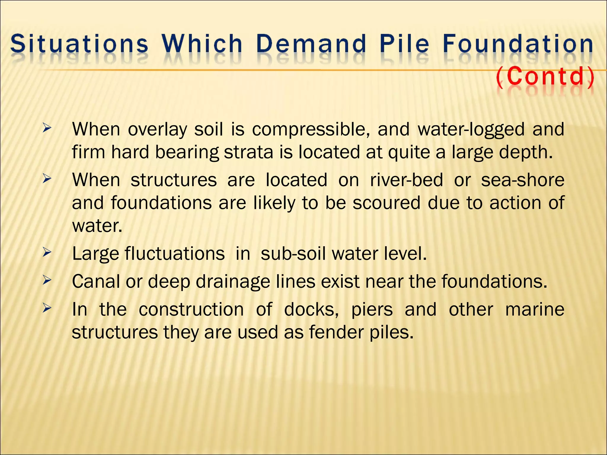
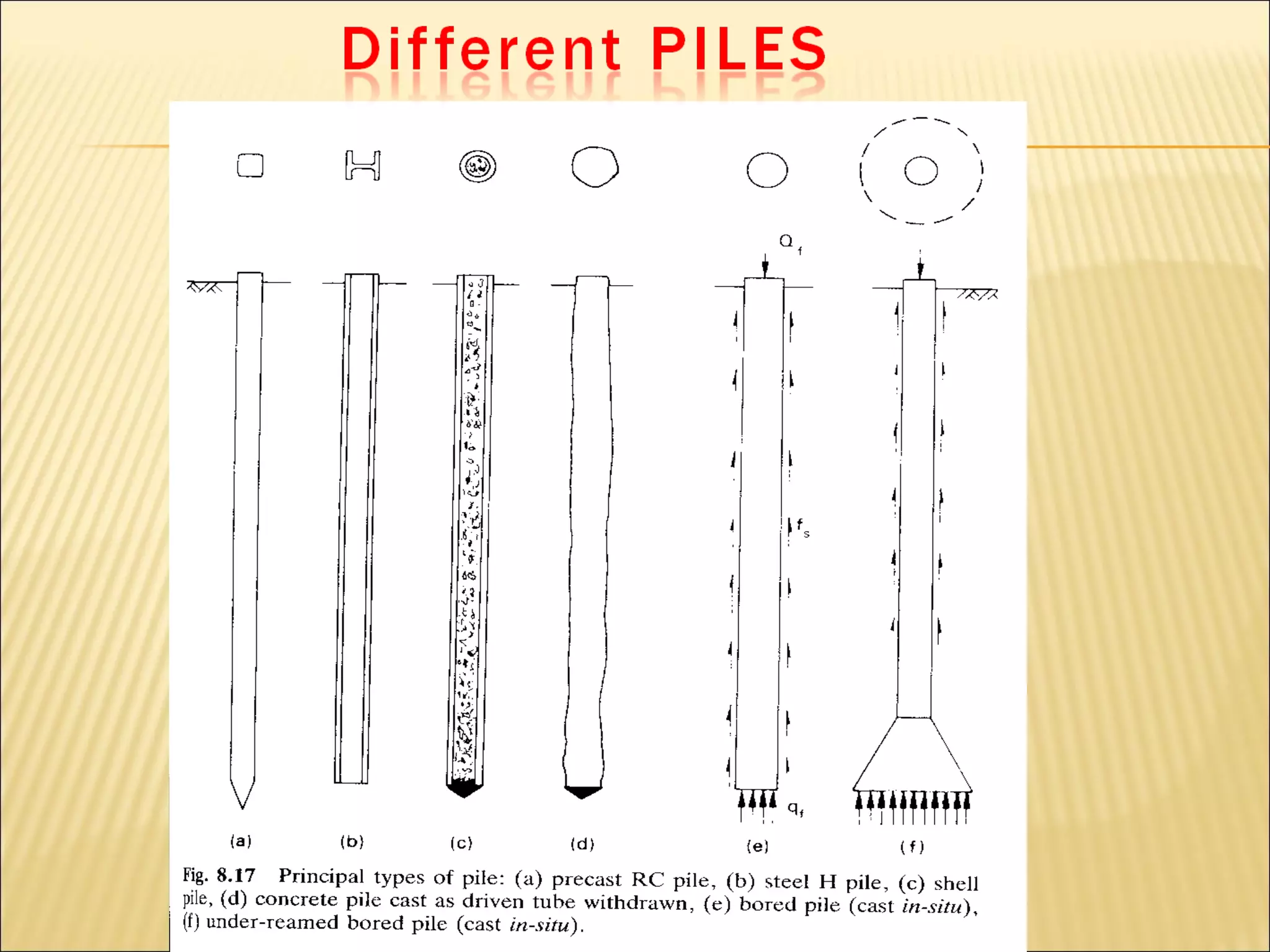
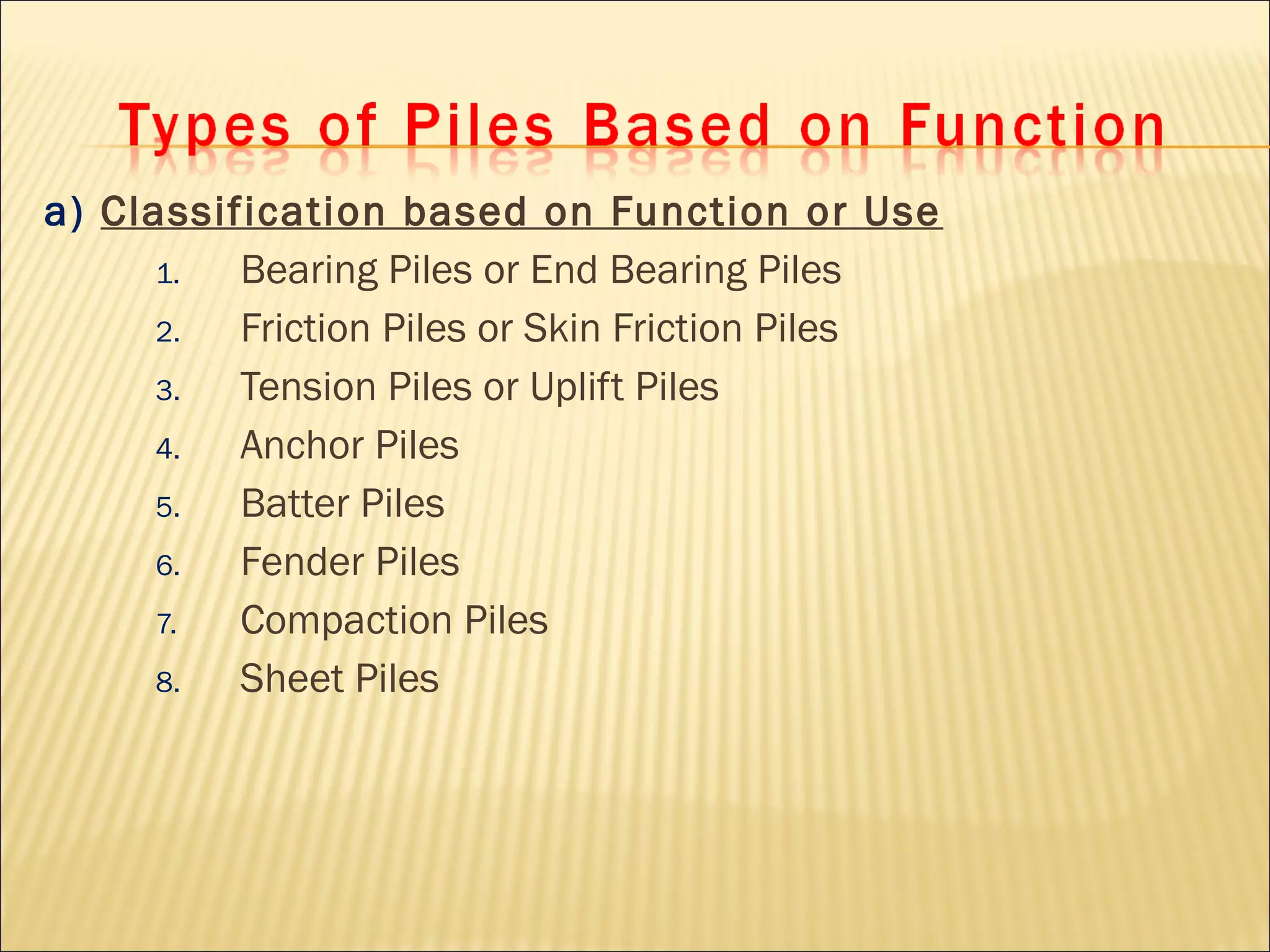
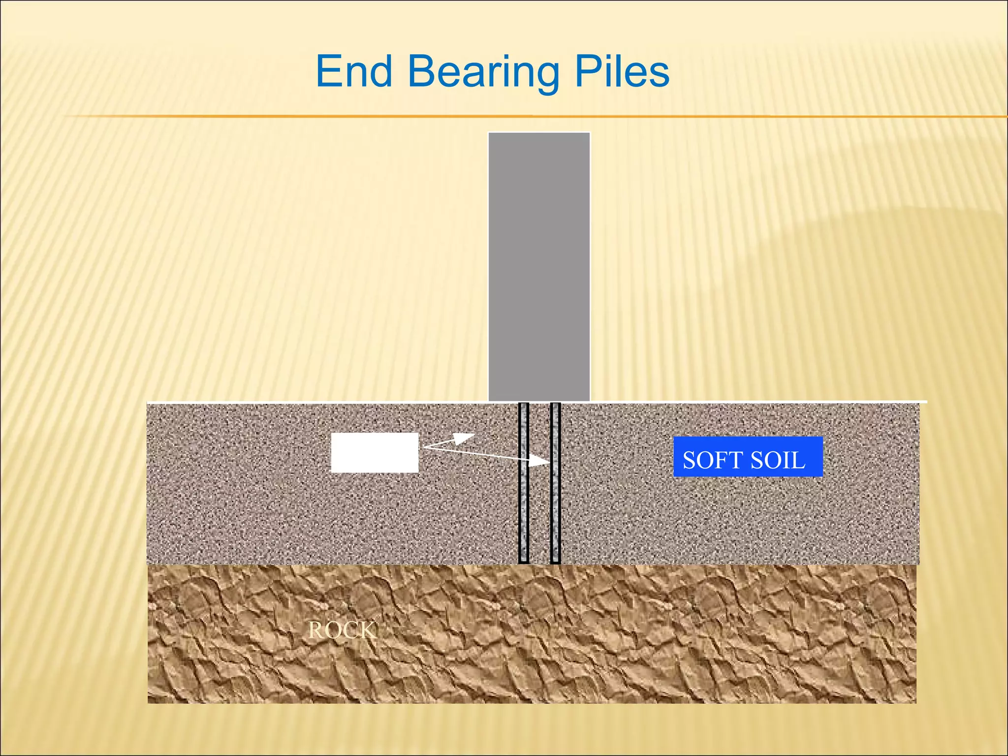
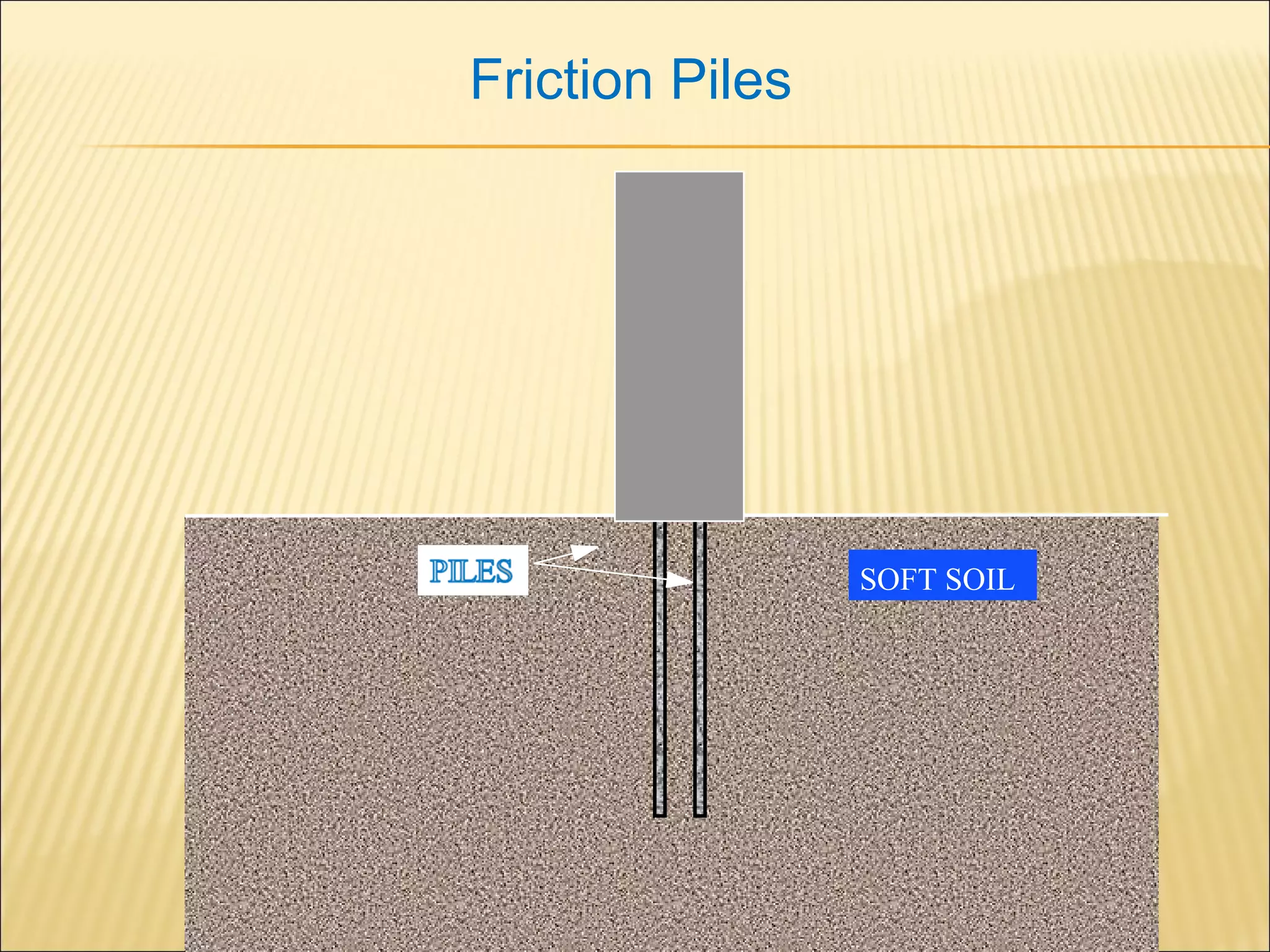
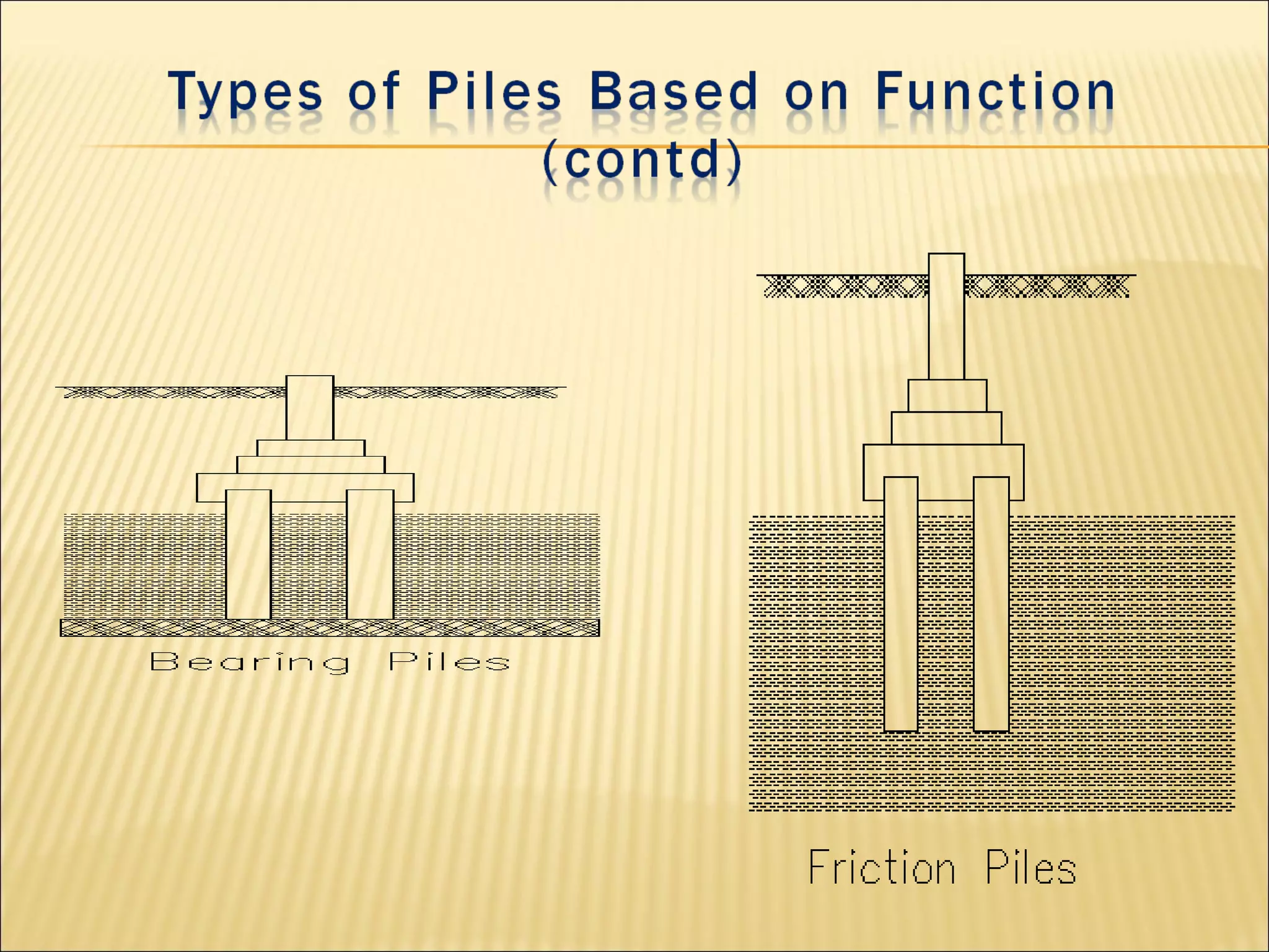
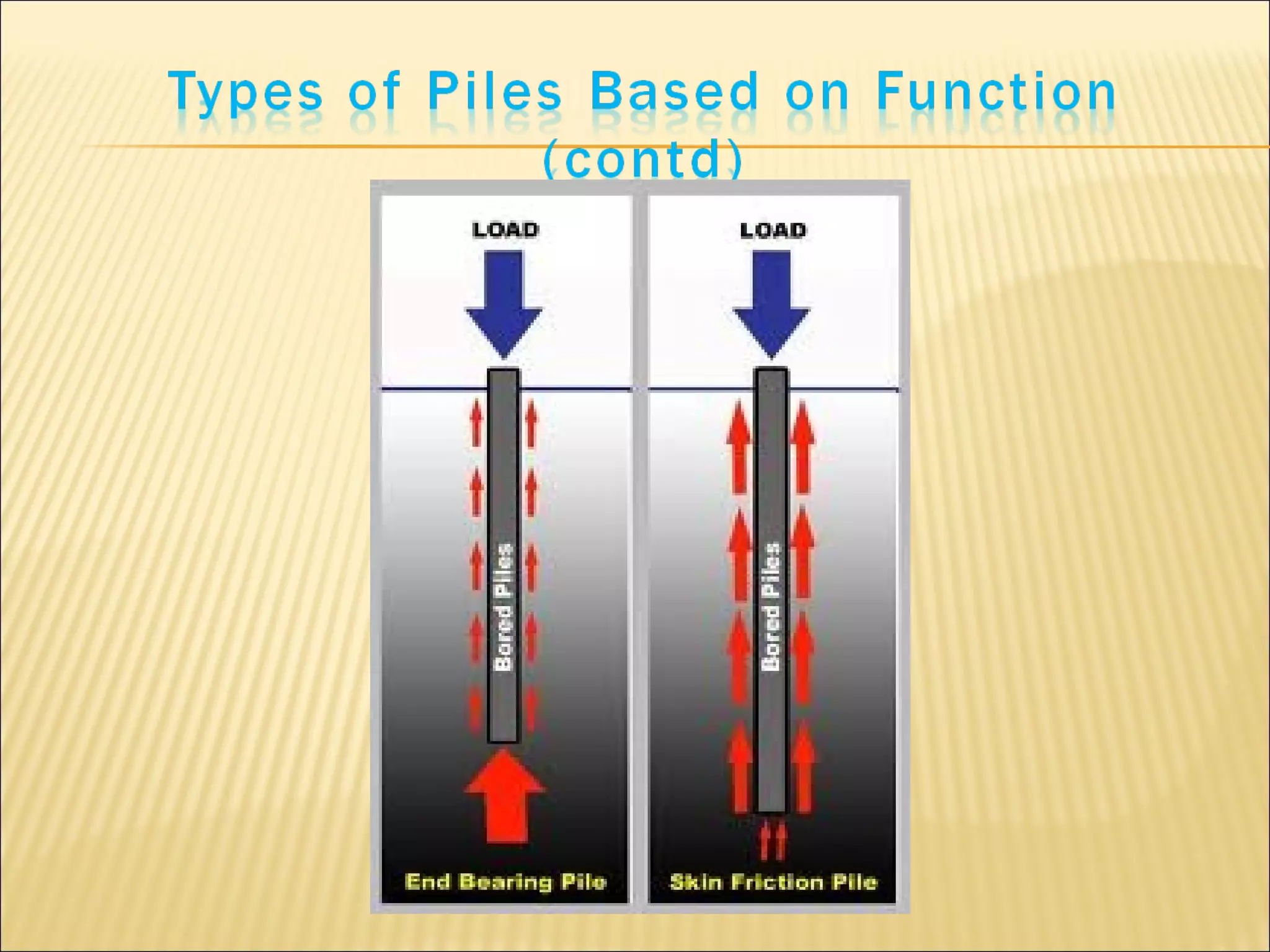
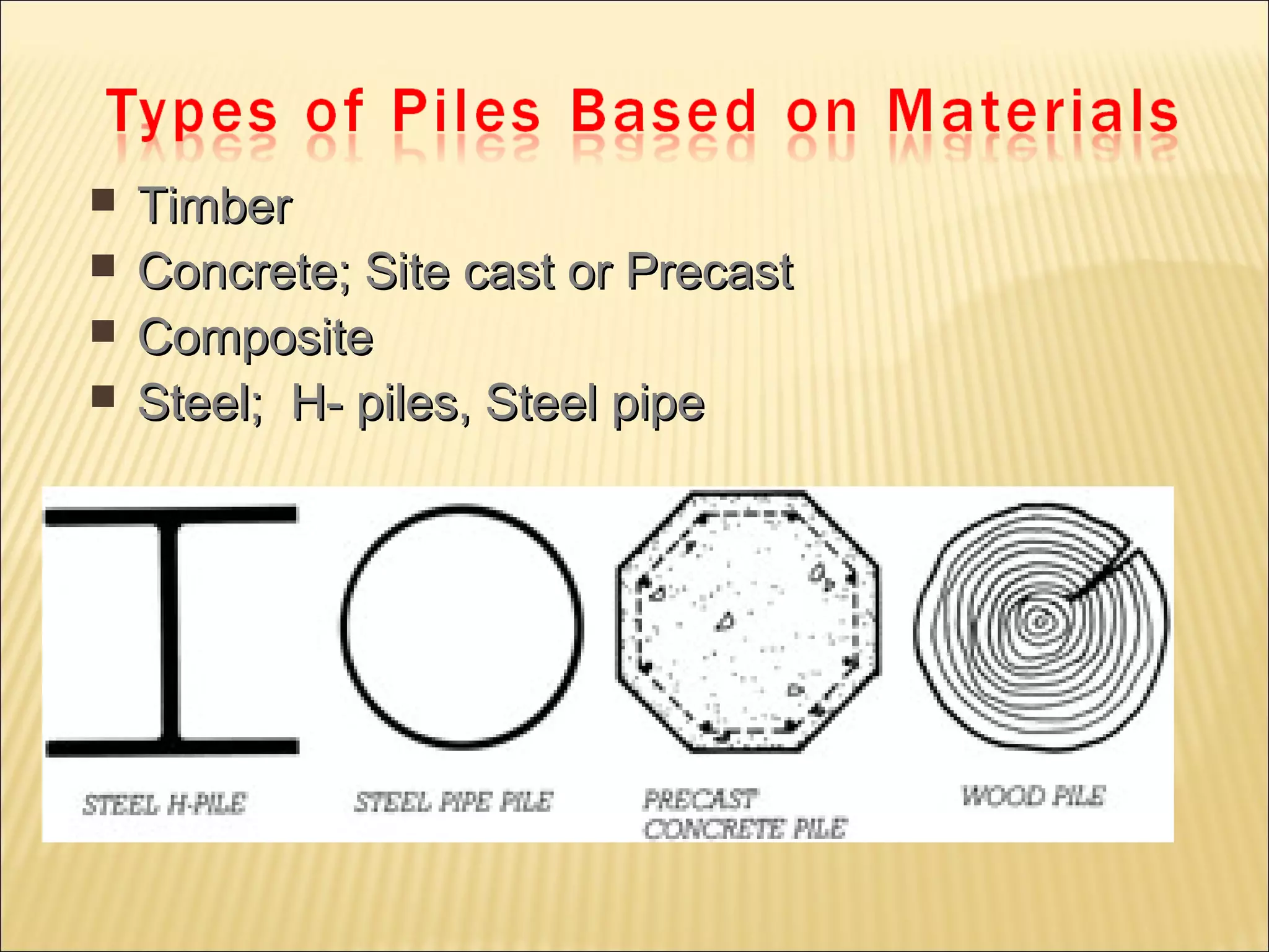
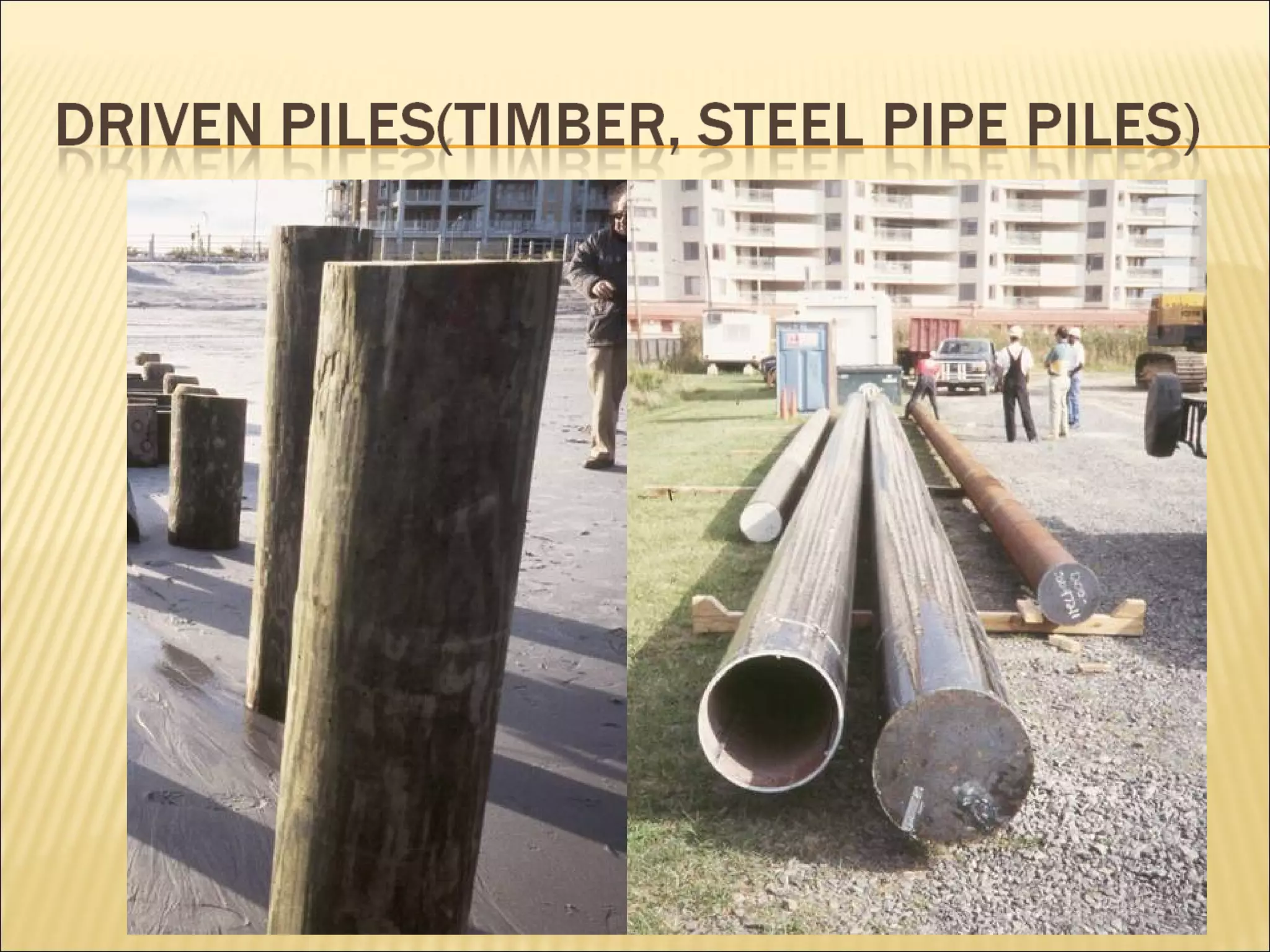
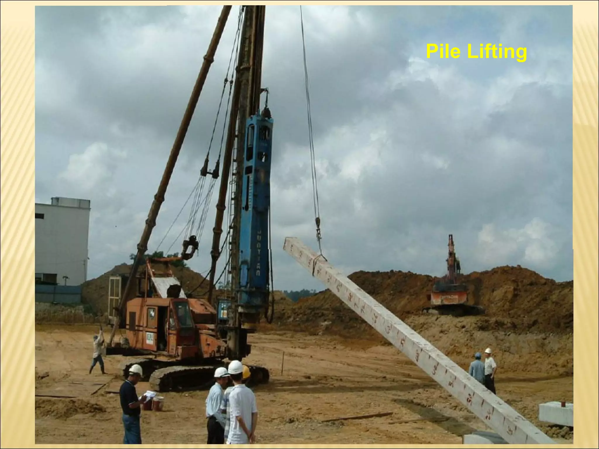
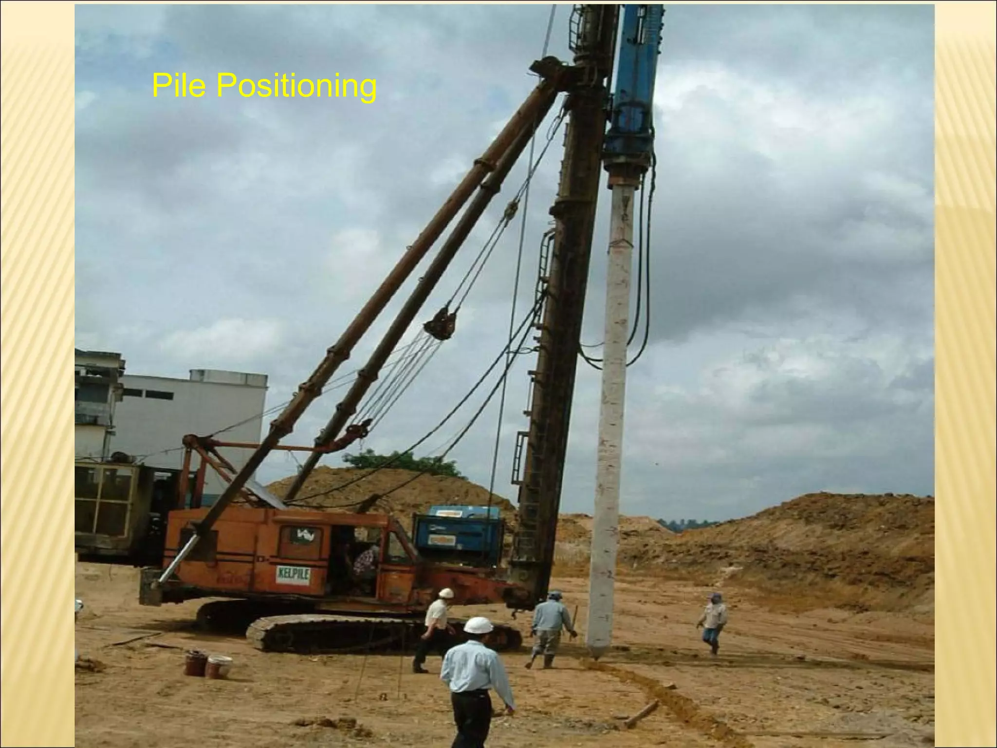
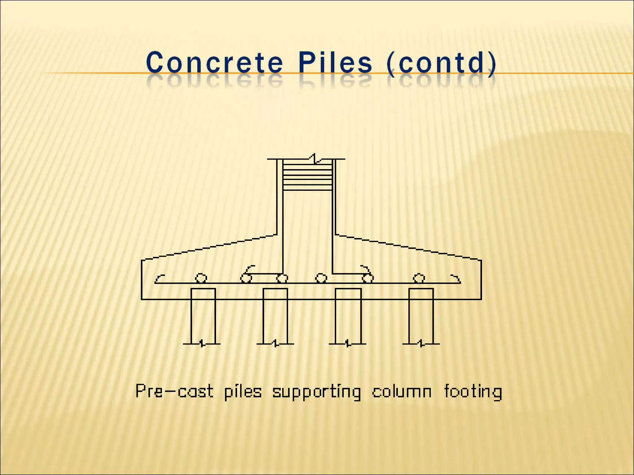
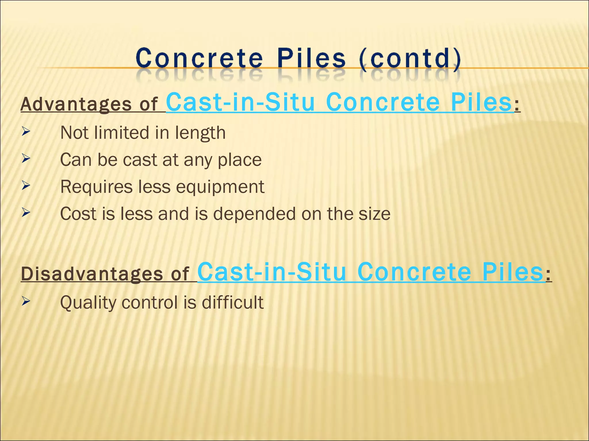
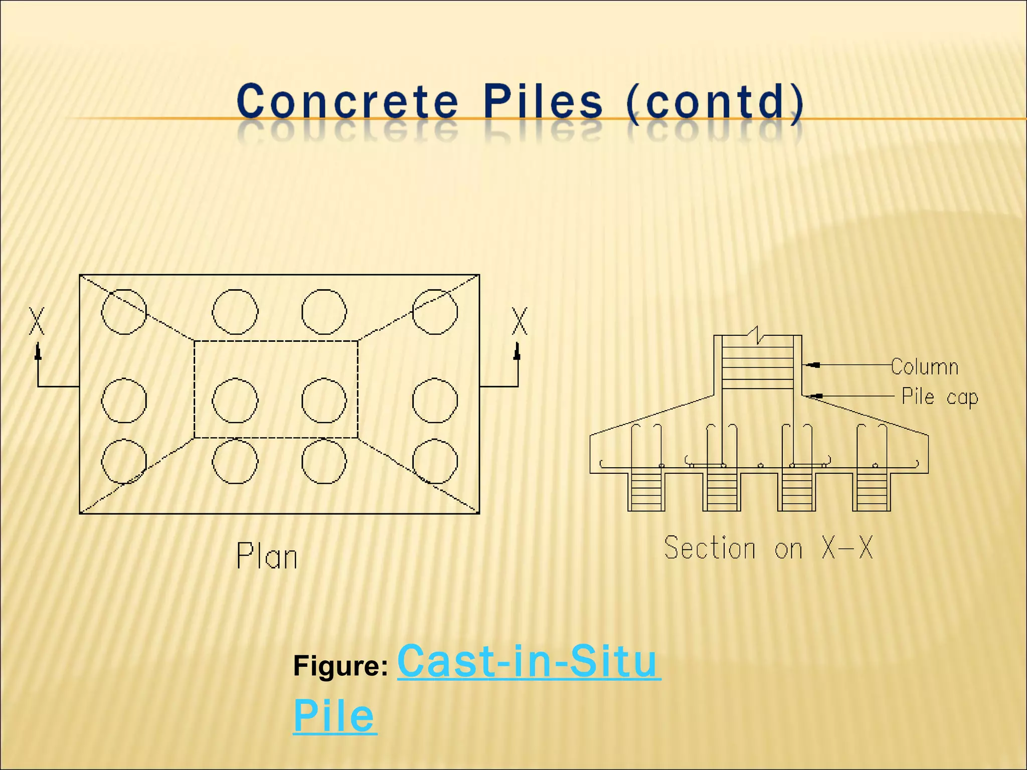
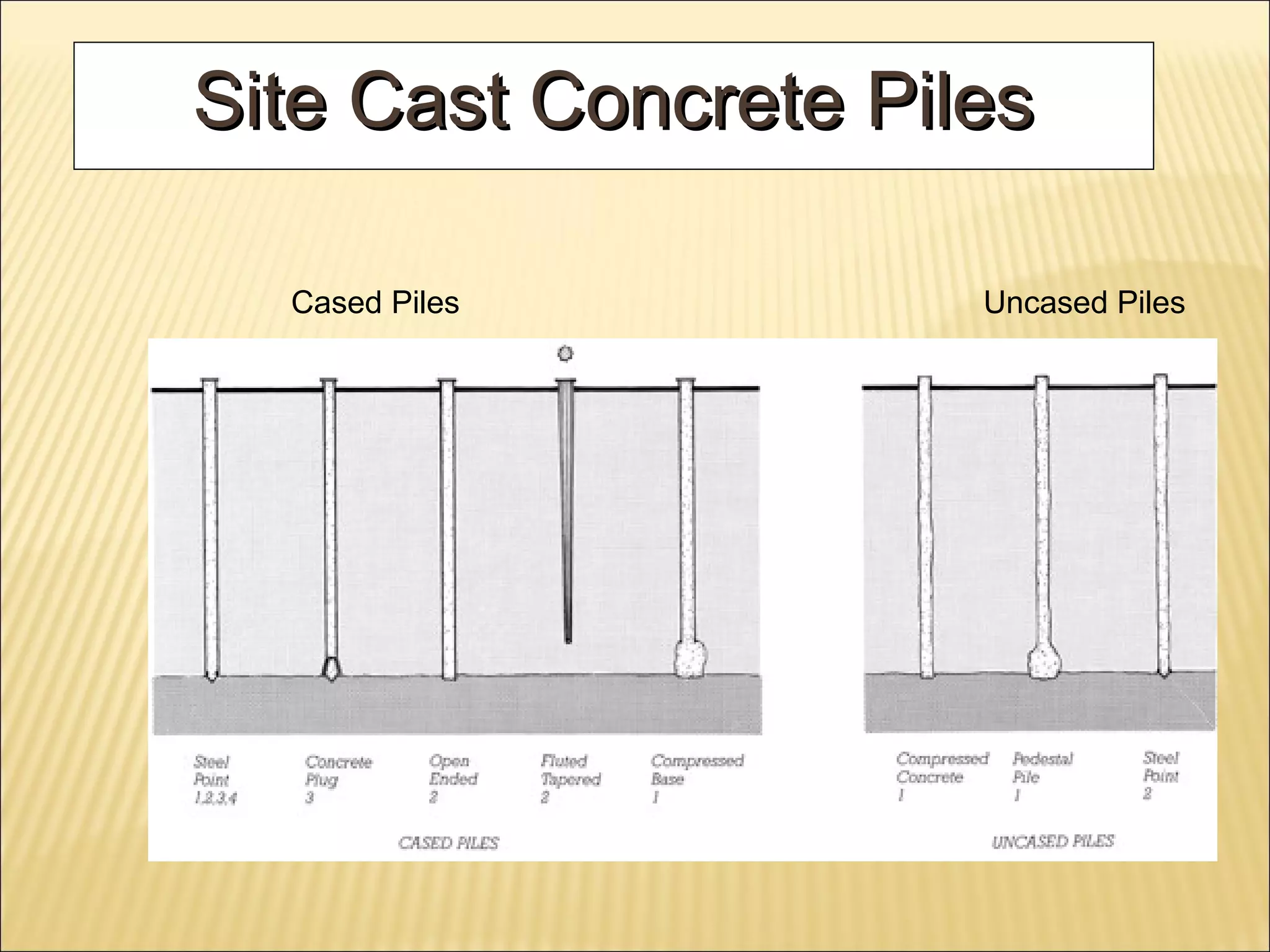
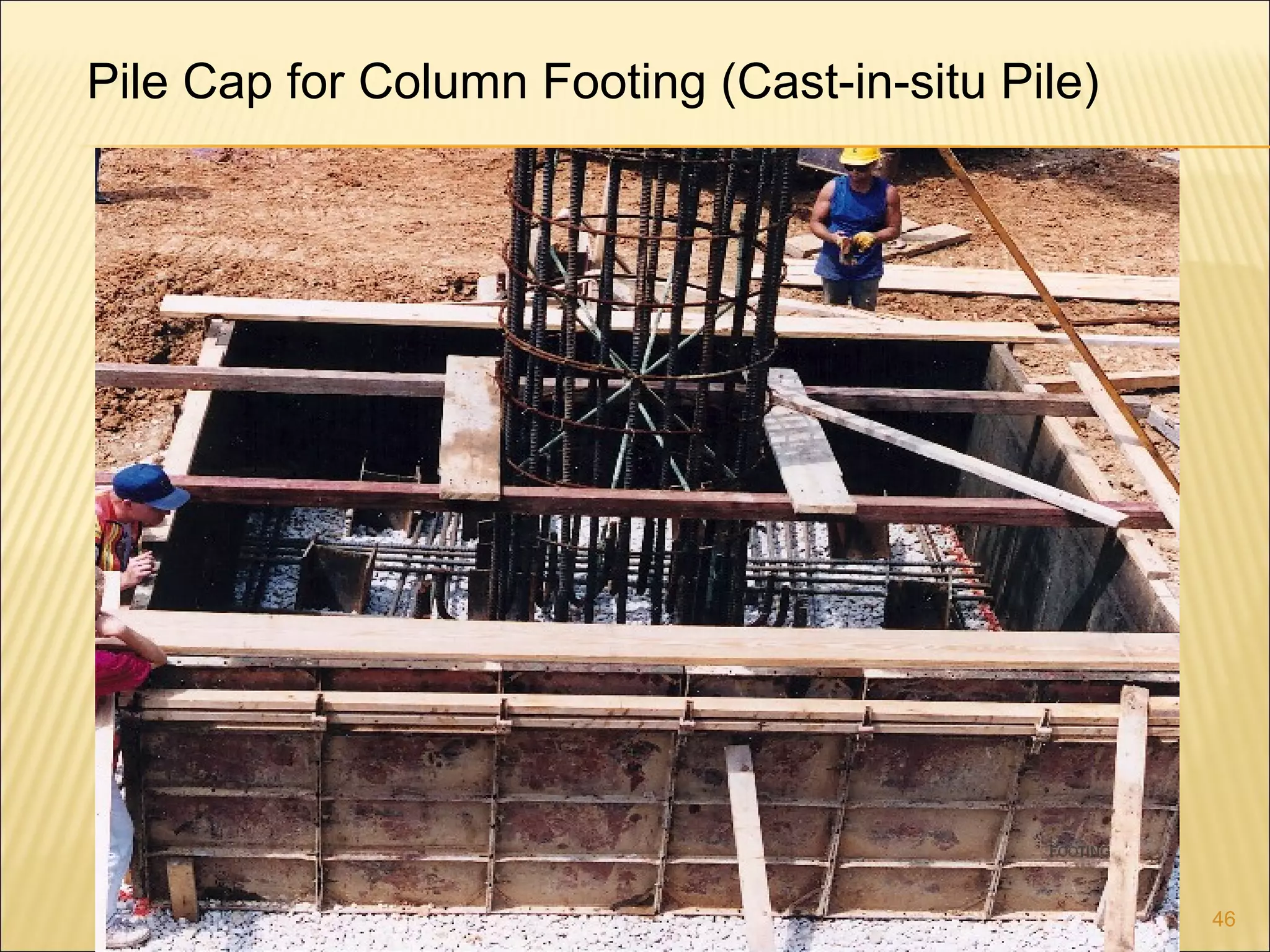
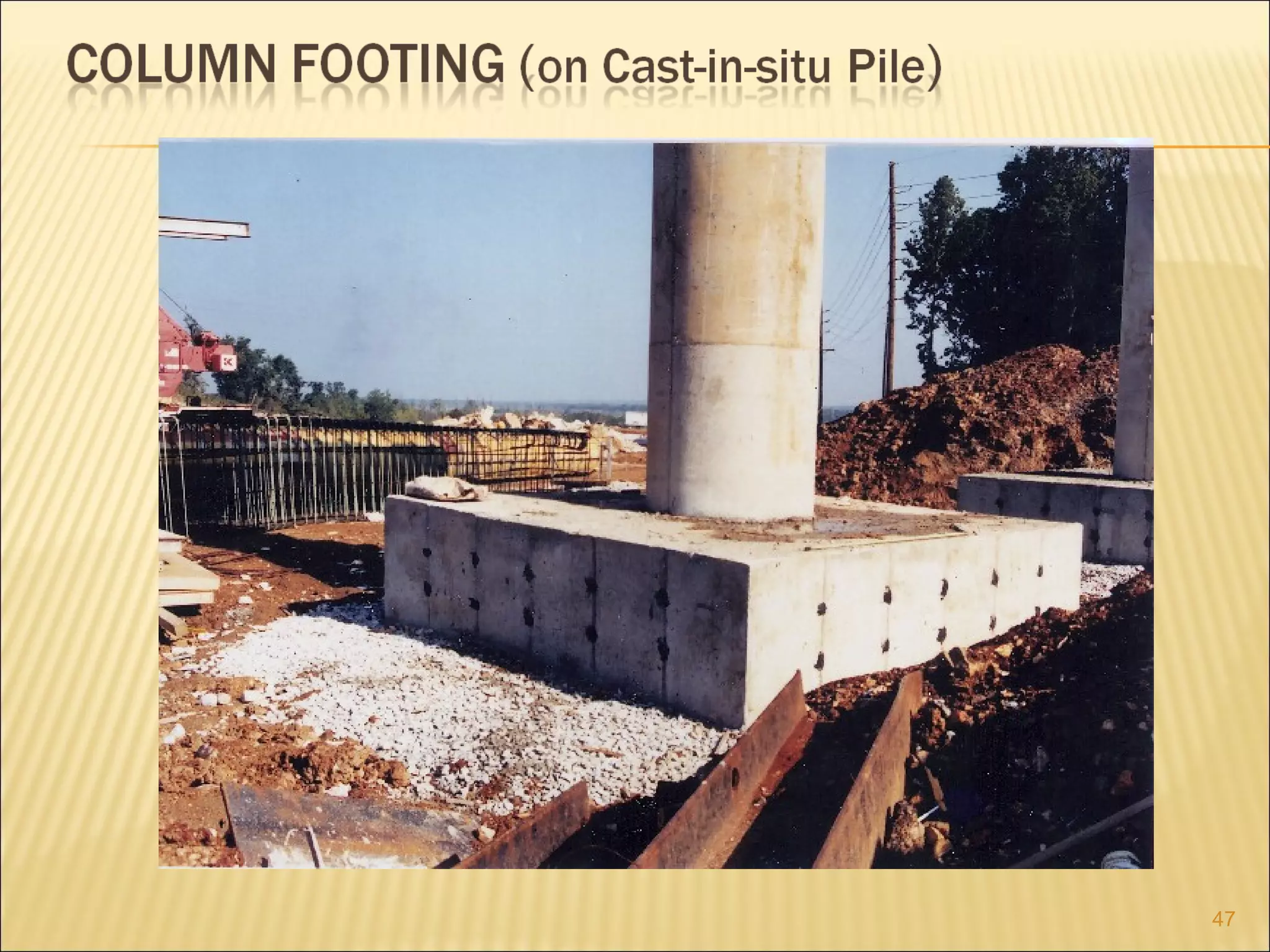
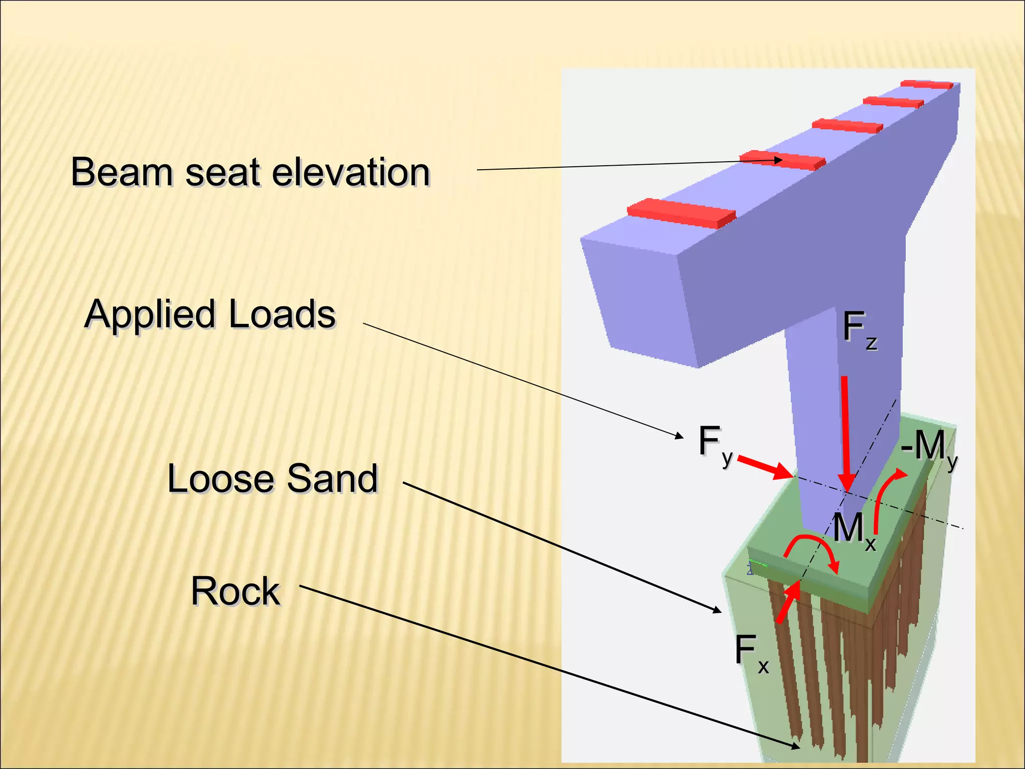
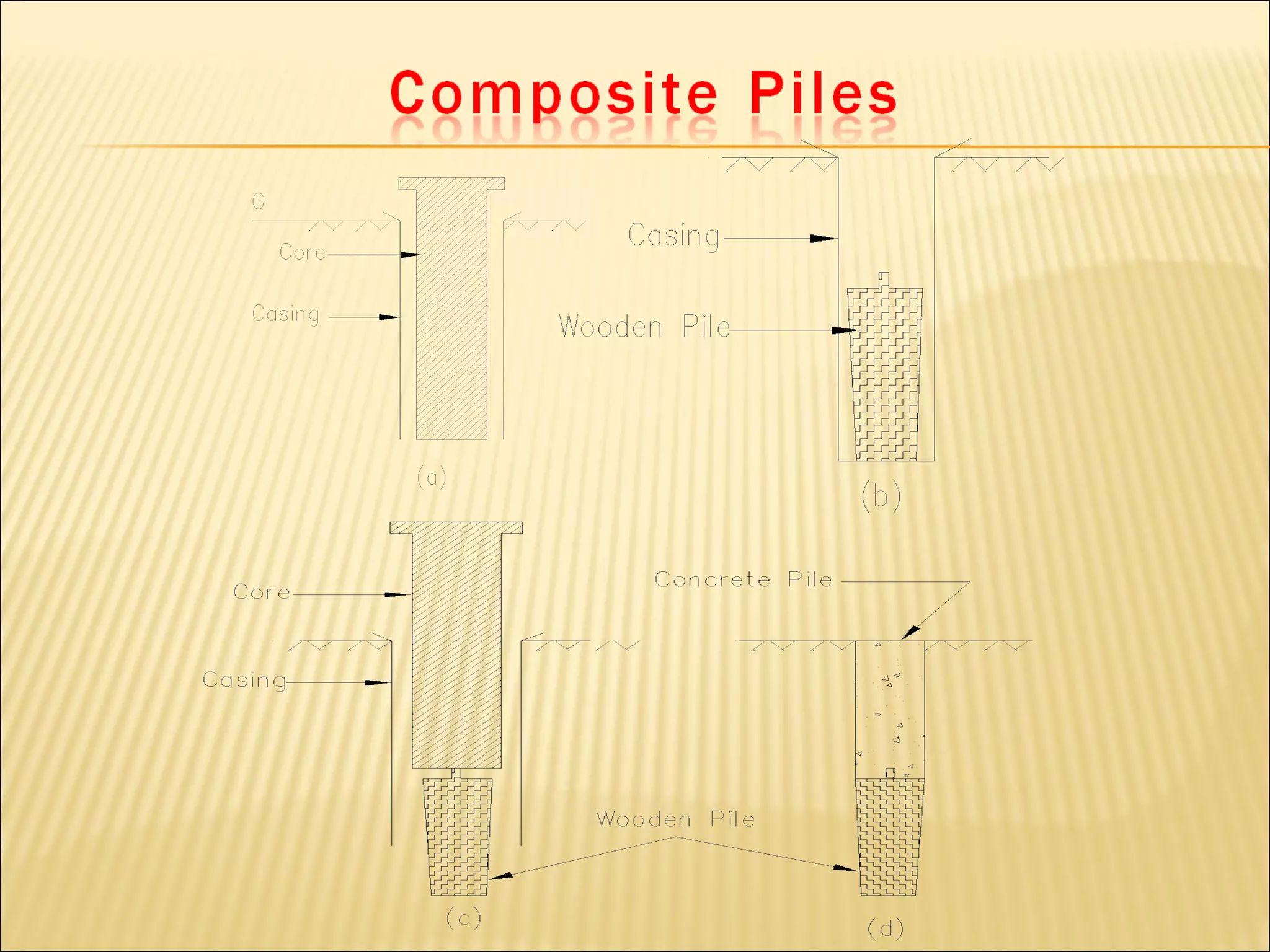
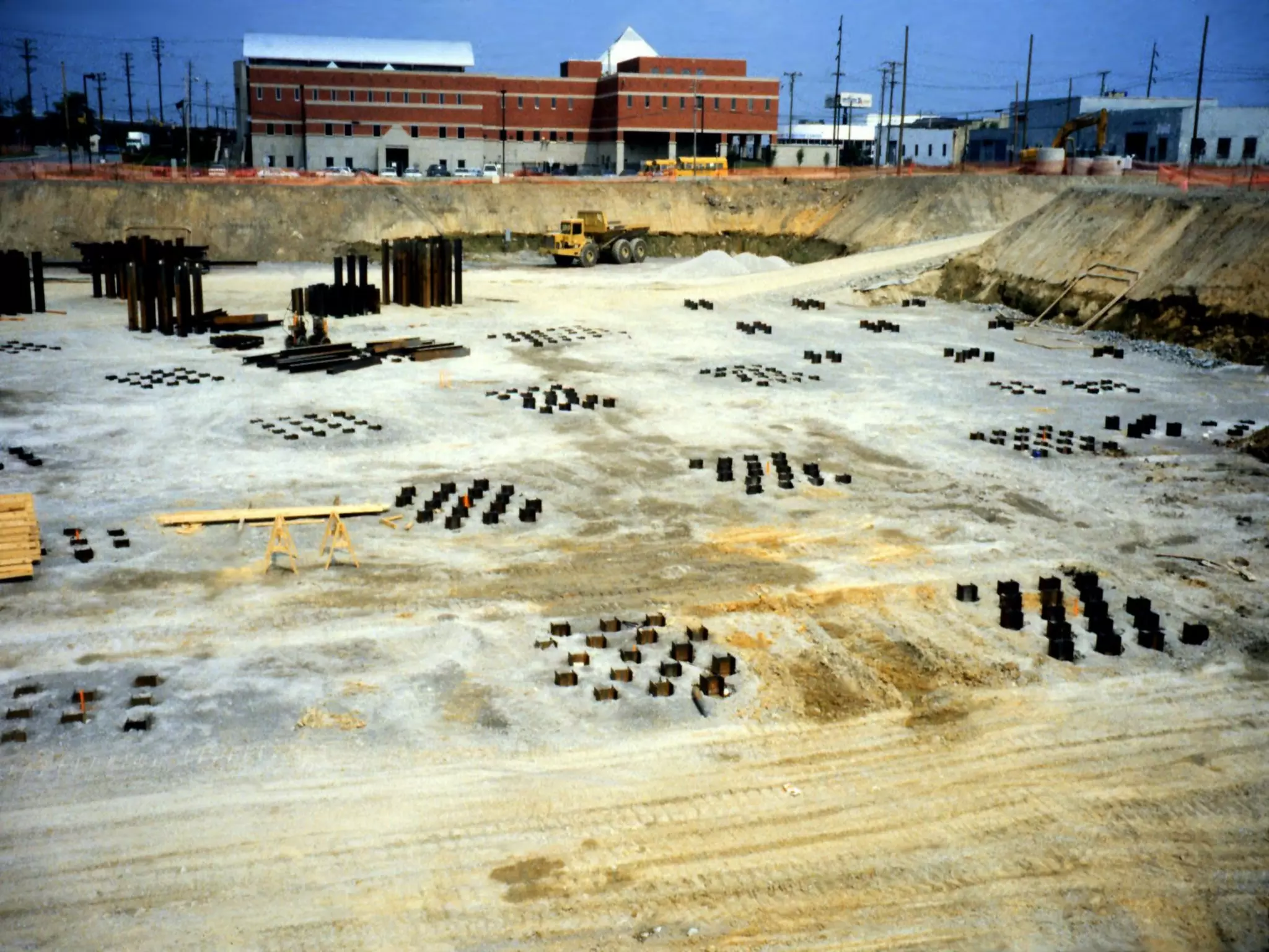
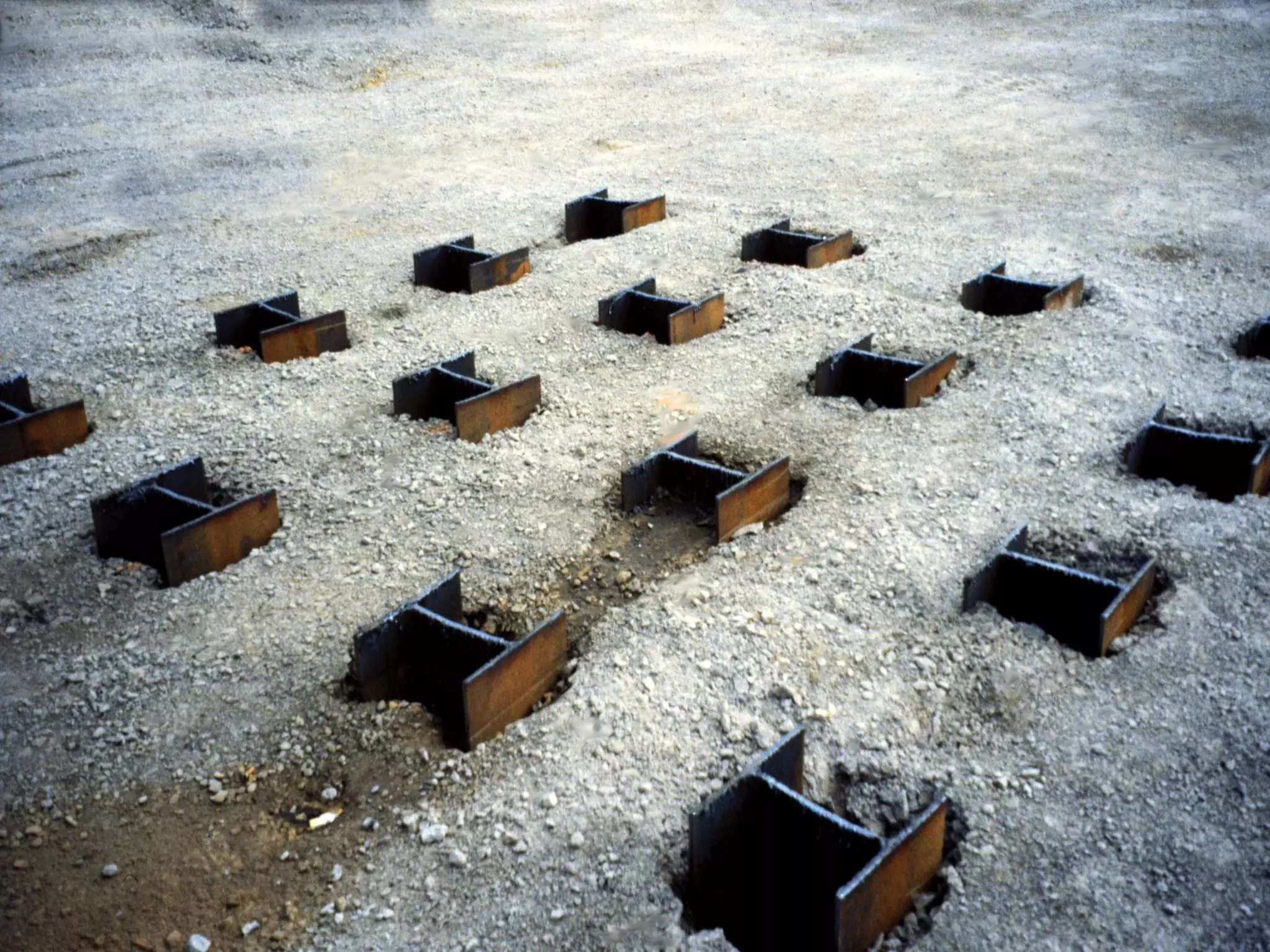
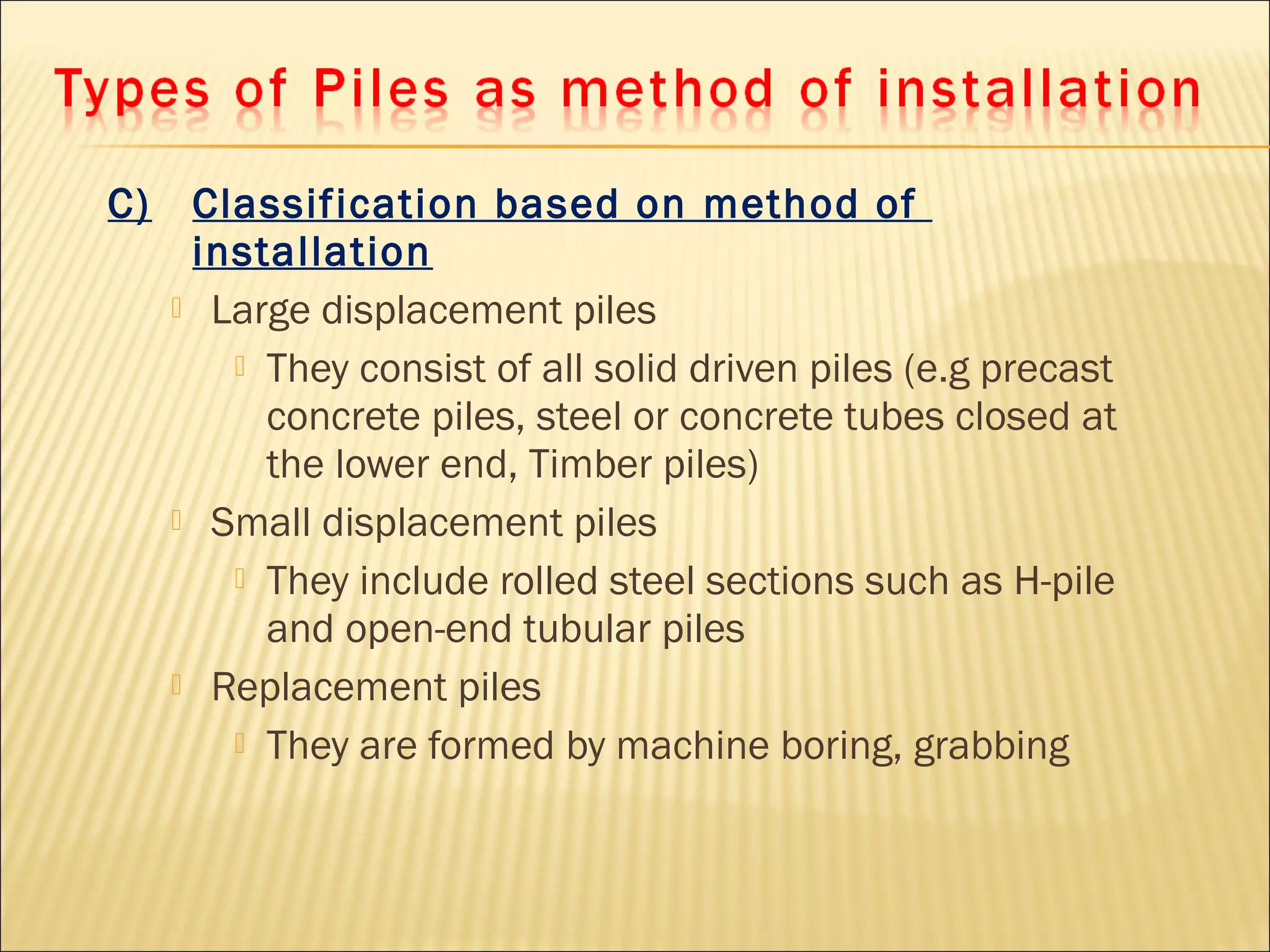
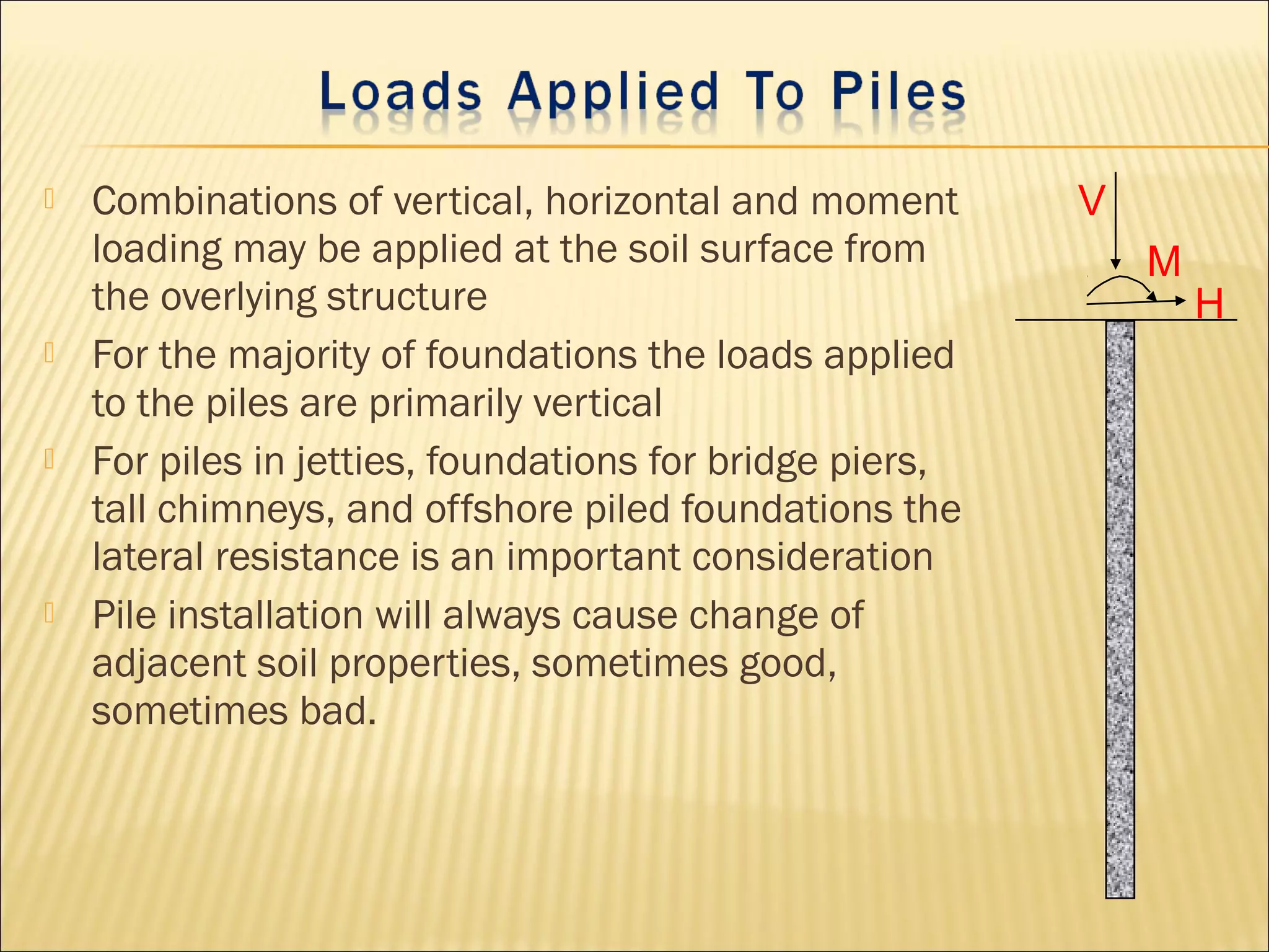
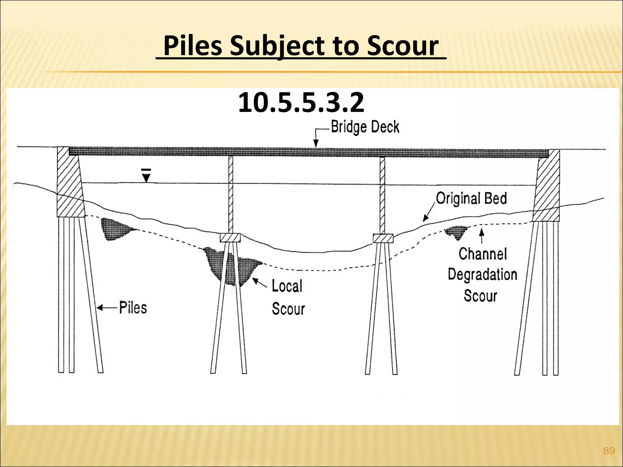
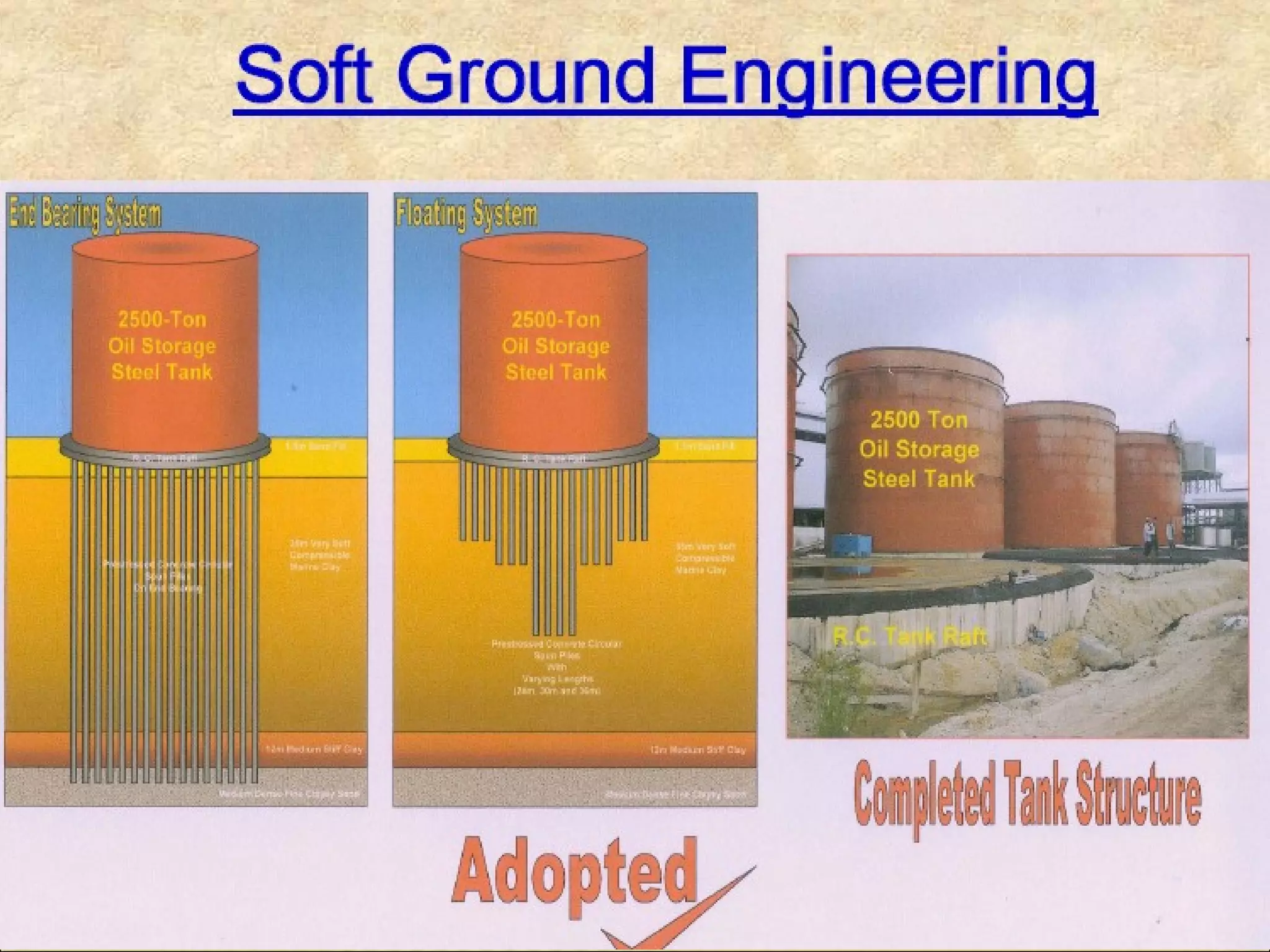
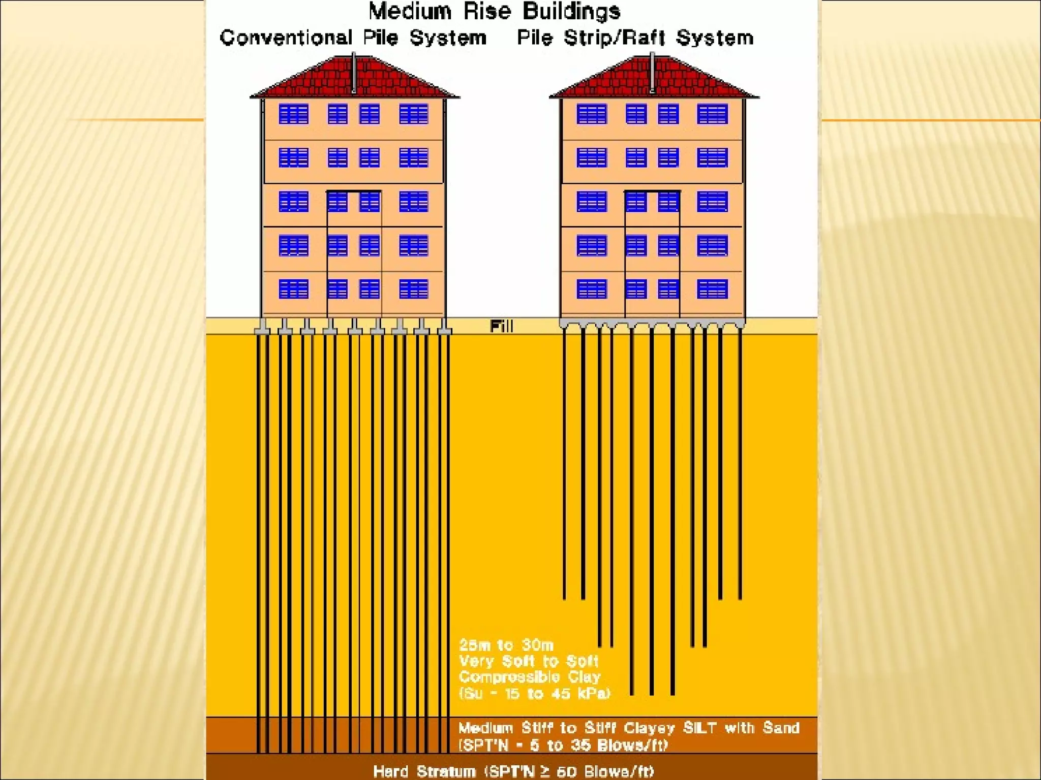
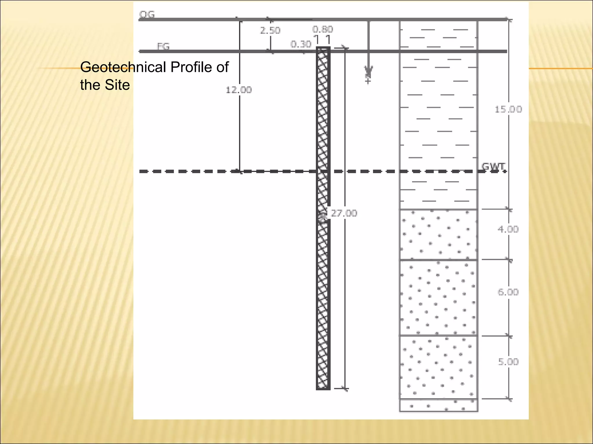
 Pile Foundation means a construction for the foundation
of a abutment or pier which is supported on piles.
 Pile is as like a column that is driven into the foundation
soil or constructed inside the foundation soil.
o When stratum of required bearing capacity is at greater depth
o Where the soil is compressible
o Where the soil is Water-logged
o Where the Soil is of made-up type
 Examples;
o Piles are used for foundation for heavy bridges,
o Buildings
o Water front installations (piers, Wharf, docks etc ).
 Provides a common solution to all difficult foundation site
problems
 Can be used for any type of structure
 Can be used in any type of soil
 Now-a-days pile foundation is vastly in use instead of well and
caisson foundation.
 Sub-soil water table is so high that it can easily affect the
other foundations.
 Load coming from the structure is heavy and non uniform.
 Where grillage or raft foundations are either very costly or
their adoption impossible due to local difficulties.
 When it is not possible to maintain foundation trenches in
dry condition by pumping, due to very heavy inflow of
seepage or capillary water.
 When it is not possible to timber the excavation trenches
in the case of deep strip foundation. (strip foundation-
spread footing under wall ).
 When overlay soil is compressible, and water-logged and
firm hard bearing strata is located at quite a large depth.
 When structures are located on river-bed or sea-shore
and foundations are likely to be scoured due to action of
water.
 Large fluctuations in sub-soil water level.
 Canal or deep drainage lines exist near the foundations.
 In the construction of docks, piers and other marine
structures they are used as fender piles.
 a) Classification based on Function or Use
 b) Classification based on Materials
 c) Classification based on method of
installation
a) Classification based on Function or Use
1. Bearing Piles or End Bearing Piles
2. Friction Piles or Skin Friction Piles
3. Tension Piles or Uplift Piles
4. Anchor Piles
5. Batter Piles
6. Fender Piles
7. Compaction Piles
8. Sheet Piles
Bearing Piles
 Driven into the ground until a hard stratum is reached.
 Acts as pillars supporting the super-structure and transmitting
the load to the ground.
 Piles, by themselves do not support the load, rather acts as a
medium to transmit the load from the foundation to the
resisting sub-stratum.
End Bearing Piles
ROCK
SOFT SOILPILES
Friction Piles
Piles are driven at a site where soil is weak or soft to a
considerable depth and it is not economical or rather
possible to rest the bottom end of the pile on the hard
stratum,
 Load is carried by the friction developed between the sides of
the pile and the surrounding ground ( skin friction).
 The piles are driven up to such a depth that skin friction
developed at the sides of the piles equals the load coming on
the piles.
Friction Piles
 Skin friction should be carefully evaluated and suitable factor
of safety applied
 The load carrying capacity of friction pile can be increased by-
 increasing diameter of the pile
 increasing the depth of pile
 increasing the number of piles (use as group of piles)
 making surface of the pile rough
SOFT SOIL
Friction Piles
Anchor Piles
 Piles are used to provide anchorage against horizontal
pull from sheet piling wall or other pulling forces.
Batter piles:
 Piles are driven at an inclination to resist large
horizontal and inclined forces.
Fender piles:
 Piles are used to protect concrete deck or other water
front structures from the abrasion or impact caused from
the ships or barges.
 Ordinarily made up of timber.
Compaction piles:
 When piles are driven in granular soil with the aim of
increasing the bearing capacity of the soil, the piles are
termed as compaction piles.
Sheet Piles
 Sheet piles are never used to provide vertical support but
mostly used to act as retaining walls. They are used for the
following purposes:
o To construct retaining walls in docks, and other marine works.
o To protect erosion of river banks.
o To retain the sides of foundation trenches.
o To confine the soil to increase its bearing capacity.
o To protect the foundation of structures from erosion by river or
sea.
o To isolate foundations from adjacent soils.
Figure: Sheet Piles
b) Classification based on Materials
1. Timber Piles
2. Concrete Piles
3. Composite Piles
4. Steel Piles
5. Sand Piles
 TimberTimber
 Concrete; Site cast or PrecastConcrete; Site cast or Precast
 CompositeComposite
 Steel; H- piles, Steel pipeSteel; H- piles, Steel pipe
1. Timber Piles:
 Transmission of load takes place by the frictional resistance of
ground and the pile surface.
 Economical to support light structure.
 Piles made from timber of tree like Sal, Teak, Deodar, Babul,
Kail etc.
 May be circular, square in x-section.
 Piles are driven with the help of pile driving machine in which
drop hammers delivers blows on the pile head.
 Brooming of pile head is prevented by providing an iron ring of
less than 25mm in diameter than the pile head at the pile top.
1. Timber Piles:
 To facilitate driving, the lower end is pointed and provided
with a cast iron conical shoe.
 Piles should not be spaced less than 60 cm center to
center, the best spacing is 90 cm c/c. closer spacing
destroys frictional resistance.
 Max load should not exceed 20 tonnes.
 Piles are subjected to decay for alternate dry and wet
condition (on account of variation of ground water level)
 Diameter varies from 30 to 50cm.
 Length should not be more than 20 times the least
sectional dimension.
Advantages of Timber Piles:
 Economical where timber is easily available.
 Can be driven rapidly & as such saves time.
 Because of elasticity, timber piles are recommended for
sites subjected to unusual lateral forces e.g. ship, ferry
terminals.
 Do not need heavy machinery and expensive technical
supervision.
 Being light, they can be easily handled.
 They can be easily withdrawn if needed.
Disadvantages of Timber Piles:
 Liable to decay or deteriorate by salt water/insects.
 Restricted length. It is rather difficult to procure piles in
required size and length.
 Low bearing capacity.
 They are not very durable unless suitably treated.
 It is difficult or rather impossible to drive these piles into
hard stratum
Advantages of Concrete piles:
 Durability is independent of ground water level.
 For large size and greater bearing power number of piles
required is much less.
 Can be cast to any length, size or shape.
 Can be used to marine work without any treatment.
 Material required for manufacture is easily obtainable.
 Concrete piles can be monolithically bonded into pile cap
which is not possible in wooden piles.
Disadvantages of Concrete piles:
 Costlier than timber piles.
 Can not be driven rapidly.
 Required costly technical supervision and heavy driving
machines.
 Must be reinforced to withstand handling stresses.
Concrete Piles are of 2 types:
a. Pre-cast Piles
b. Cast in situ Piles
a. Pre-cast Piles:
 Reinforced concrete piles, molded in circular, square,
rectangular or octagonal form.
 Cast and cured in the casting yard, then transported to the
site of driving.
 If space available it can be cast and cured near the work site.
 Driven in similar manner as timber piles with the help of piles
drivers.
 Diameter normally varies from 35cm to 65cm, length varies
from 4.5m to 30m.
a. Pre-cast Piles:
 Function of reinforcement in a pre-cast pile is to resist the
stresses during handling, driving and final loading on the pile
rather than strengthen the pile to act as a column.
 Longitudinal reinforcements usually 20mm to 50mm in
diameter, stirrups 6mm to 10mm in dia.
 For 90 cm length at head and toe, stirrups spacing is 8cm c/c
and for remaining intermediate length it is about 30cm c/c.
 A concrete cover of 5cm is maintained throughout, over the
main steel bars.
Advantages of Pre-cast Piles:
 Very effective
 Simple quality control
 Improves the entire area
Disadvantages of Pre-cast Piles:
 Limited in length
 Difficult to transport
 Not suitable for densely built up area
 Requires costly equipment
 Size : 150mm to 400mm
 Lengths : 3m, 6m, 9m and 12m
 Structural Capacity : 25Ton to 185Ton
 Material : Grade 40MPa Concrete
 Joints: Welded
 Installation Method : Drop Hammer
Precast Concrete PliesPrecast Concrete Plies
RCC
Square
Piles
Pile Lifting
Pile Positioning
b. Cast-in-Situ Piles:
 Cast in position inside the ground.
 First of all a bore is dug
 Then the soil from the bore is drawn out
 Reinforce cage is placed in
 and filled with cement concrete
Advantages of Cast-in-Situ Concrete Piles:
 Not limited in length
 Can be cast at any place
 Requires less equipment
 Cost is less and is depended on the size
Disadvantages of Cast-in-Situ Concrete Piles:
 Quality control is difficult
Figure: Cast-in-Situ
Pile
Site Cast Concrete PilesSite Cast Concrete Piles
Cased Piles Uncased Piles
46
Pile Cap for Column Footing (Cast-in-situ Pile)
47
FFzz
FFyy
FFxx
-M-Myy
MMxx
Beam seat elevationBeam seat elevation
RockRock
Loose SandLoose Sand
Applied LoadsApplied Loads
 Piles of two different materials are driven one over the other,
so as to enable them to act together to perform the function
of a single pile.
 This type of composite pile is used with the object of
achieving economy in the cost of piling work.
 Steel piles are of steel section. Useful where driving
conditions are difficult and other types of piles are not suitable.
Usually used for building and bridge foundations. The piles are
in form of I, H sections and steel pipe piles.
 Steel piles are available in the following forms.
 Steel H piles
 Sheet piles
 Disc piles
 Screw piles.
 Similar to I-beam except that cross-section is generally
heavier and the flange width and distance from flange
face to flange face is nearly the same.
The following photo sequence was taken at the site of the NashvilleThe following photo sequence was taken at the site of the Nashville
ColiseumColiseum
67,000 seat sports Stadium in Nashville, TN67,000 seat sports Stadium in Nashville, TN
–Deep Foundations is adoptedDeep Foundations is adopted::
 3,500 Driven Piles; 12x53 H Piles (End Bearing)3,500 Driven Piles; 12x53 H Piles (End Bearing)
 Pile length varied from 25’-75’Pile length varied from 25’-75’
 Used 3 Pile Drivers (Diesel Powered Hammers)Used 3 Pile Drivers (Diesel Powered Hammers)
 Driving rate: 20-25 piles/day/rigDriving rate: 20-25 piles/day/rig
C) Classification based on method of
installation
 Large displacement piles
 They consist of all solid driven piles (e.g precast
concrete piles, steel or concrete tubes closed at
the lower end, Timber piles)
 Small displacement piles
 They include rolled steel sections such as H-pile
and open-end tubular piles
 Replacement piles
 They are formed by machine boring, grabbing
 Combinations of vertical, horizontal and moment
loading may be applied at the soil surface from
the overlying structure
 For the majority of foundations the loads applied
to the piles are primarily vertical
 For piles in jetties, foundations for bridge piers,
tall chimneys, and offshore piled foundations the
lateral resistance is an important consideration
 Pile installation will always cause change of
adjacent soil properties, sometimes good,
sometimes bad.
H
V
M
 The nature of the ground, where piling operation is to be
carried out, determines to a large extent the choice of type of
pile to be used.
 In addition, the other important factors which must be
considered in this regard are:
o The nature of the structure.
o Loading conditions.
o Elevation of the ground water level with respect to the pile cap.
o Probable length of pile required.
o Availability of materials and equipment.
o Factors which may cause deterioration of pile.
o Probable cost of pile.
 Load on the pile is more than the designed load.
 Defective workmanship during casting of the pile.
 Displacement of reinforcement during casting.
 Bearing pile resting on a soft strata.
 Improper classification of soil.
 Improper choice of the type of pile.
 Insufficient reinforcement in the pile.
 Decay of timber piles due to attack by insects.
 Buckling of piles due to inadequate lateral support.
 Defective method adopted for driving the pile.
 Incorrect assessment of the bearing capacity of the pile.
 Lateral forces not considered in the design of piles.
I. Hammering.
II. Water Jets (Wash Boring ).
III. Boring (Auger Boring).
 Drop Hammer.
 Steam Hammer: single-acting, double-acting
 Air Hammer: single-acting, double-acting,
 Diesel hammer: single-acting (open end) or
double-acting (closed end)
 Hydraulic Hammer
 Vibratory Hammer
 The drop hammer is the simplest and oldest type of
impact hammer. A hammer with approximately the
weight of the pile is raised a suitable height in a guide
and released to strike the pile head. This is a simple
form of hammer.
 Hammer is raised by a rope or a steel cable
 Then it is allowed to drop on pile cap
 The weight of drop varies from 230-1800 kg
 Weight depends on the shape and length of
pile and the nature of the ground
 Takes a lot of time
 Hammer is automatically raised and dropped.
 A steam cylinder and piston is used.
 Steam pressure and the rate of hammer blow
are kept uniform.
 Steam Hammers are of two types
 Single Acting Type
 Double Acting Type
Pile Driving
 Equipment
 mobile crane (usually
crawler)
 leads: fixed or swinging
 hammer, helmet, & cushion
 compressor (if air driven)
 hydraulic unit (if vibratory)
 steam plant (becoming
obsolete)
 Wash boring is a fast and simple method for advancing holes in
soft to stiff cohesive soils and fine sand. This method is nt
suitable for boulders soil and rock.
 The method consists of first driving a hollow steel pipe known as
casing pipe/drive pipe in to the ground.
 Through this casing pipe, a hollow drilled rod with a sharp chisel or
chopping bit at the lower end known as water jet pipe or wash pipe
is inserted.
 Upper end of wash pipe is connected to water pump and lower end
is contracted to produce jet action.
 Water is forced under pressure through the drill rod which is
alternatively raised and dropped, and also rotated. The resulting
chopping and jetting action of the bit and water disintegrates the
soil.
 The cuttings are forced up to the ground surface in the form of soil-
water slurry through the annular space between the drill rod and
the casing.
 The slurry is collected and samples of materials are obtained by
settlement.
Interpretation of Results
 The change in soil stratification is guessed from the rate of
progress of driving the casing pipe and from the color of slurry
flowing out.
 Results give fairly good information about the nature of the sub-soil
strata.
Disadvantages
 Finer particles such as clay, loam etc do not settle easily.
 Larger and heavy particles may not be brought up at all.
 Exact location of materials (in bore length) can not be easily
determined.
 Cast-In In-Situ Piles may be of Large Diameter
 Size : 450mm to 2m (Up to 3.0m for special case)
 Lengths : Varies
 Structural Capacity : 80Ton to 2,300Tons
 Concrete Grade : 20MPa to 35MPa (Tremie)
 Joints : None
 Installation Method : Drill then Cast-In-Situ
Boring method is adopted for in-situ piles in hard soil or
soft rock.
Various boring methods are given following;
Percussion method
Augur Boring method
Rotary Drilling
Steps in augar/rotary drilling;
Boring is continued down to planned depth (using a guiding
tube/rod)
Using bentonite mud (slurry) under the groundwater level
Placing of reinforcement
Placing of the concrete and removing off the guiding tube
LooseLoose
Silty sandSilty sand
Hard ClayHard Clay
DrivenDriven
HP 12 x 53HP 12 x 53
4'
35'
>100’
φf = 31o
γsat = 110 pcf
γsat = 125 pcf
Piles Subject to Scour
10.5.5.3.2
89
Geotechnical Profile of
the Site

Pile foundation ppt 2 (usefulsearch.org) (useful search)

  • 2.
     Pile Foundationmeans a construction for the foundation of a abutment or pier which is supported on piles.  Pile is as like a column that is driven into the foundation soil or constructed inside the foundation soil.
  • 3.
    o When stratumof required bearing capacity is at greater depth o Where the soil is compressible o Where the soil is Water-logged o Where the Soil is of made-up type  Examples; o Piles are used for foundation for heavy bridges, o Buildings o Water front installations (piers, Wharf, docks etc ).
  • 4.
     Provides acommon solution to all difficult foundation site problems  Can be used for any type of structure  Can be used in any type of soil  Now-a-days pile foundation is vastly in use instead of well and caisson foundation.
  • 5.
     Sub-soil watertable is so high that it can easily affect the other foundations.  Load coming from the structure is heavy and non uniform.  Where grillage or raft foundations are either very costly or their adoption impossible due to local difficulties.  When it is not possible to maintain foundation trenches in dry condition by pumping, due to very heavy inflow of seepage or capillary water.  When it is not possible to timber the excavation trenches in the case of deep strip foundation. (strip foundation- spread footing under wall ).
  • 6.
     When overlaysoil is compressible, and water-logged and firm hard bearing strata is located at quite a large depth.  When structures are located on river-bed or sea-shore and foundations are likely to be scoured due to action of water.  Large fluctuations in sub-soil water level.  Canal or deep drainage lines exist near the foundations.  In the construction of docks, piers and other marine structures they are used as fender piles.
  • 7.
     a) Classificationbased on Function or Use  b) Classification based on Materials  c) Classification based on method of installation
  • 9.
    a) Classification basedon Function or Use 1. Bearing Piles or End Bearing Piles 2. Friction Piles or Skin Friction Piles 3. Tension Piles or Uplift Piles 4. Anchor Piles 5. Batter Piles 6. Fender Piles 7. Compaction Piles 8. Sheet Piles
  • 10.
    Bearing Piles  Driveninto the ground until a hard stratum is reached.  Acts as pillars supporting the super-structure and transmitting the load to the ground.  Piles, by themselves do not support the load, rather acts as a medium to transmit the load from the foundation to the resisting sub-stratum.
  • 11.
  • 12.
    Friction Piles Piles aredriven at a site where soil is weak or soft to a considerable depth and it is not economical or rather possible to rest the bottom end of the pile on the hard stratum,  Load is carried by the friction developed between the sides of the pile and the surrounding ground ( skin friction).  The piles are driven up to such a depth that skin friction developed at the sides of the piles equals the load coming on the piles.
  • 13.
    Friction Piles  Skinfriction should be carefully evaluated and suitable factor of safety applied  The load carrying capacity of friction pile can be increased by-  increasing diameter of the pile  increasing the depth of pile  increasing the number of piles (use as group of piles)  making surface of the pile rough
  • 14.
  • 17.
    Anchor Piles  Pilesare used to provide anchorage against horizontal pull from sheet piling wall or other pulling forces. Batter piles:  Piles are driven at an inclination to resist large horizontal and inclined forces.
  • 18.
    Fender piles:  Pilesare used to protect concrete deck or other water front structures from the abrasion or impact caused from the ships or barges.  Ordinarily made up of timber. Compaction piles:  When piles are driven in granular soil with the aim of increasing the bearing capacity of the soil, the piles are termed as compaction piles.
  • 20.
    Sheet Piles  Sheetpiles are never used to provide vertical support but mostly used to act as retaining walls. They are used for the following purposes: o To construct retaining walls in docks, and other marine works. o To protect erosion of river banks. o To retain the sides of foundation trenches. o To confine the soil to increase its bearing capacity. o To protect the foundation of structures from erosion by river or sea. o To isolate foundations from adjacent soils.
  • 21.
  • 22.
    b) Classification basedon Materials 1. Timber Piles 2. Concrete Piles 3. Composite Piles 4. Steel Piles 5. Sand Piles
  • 23.
     TimberTimber  Concrete;Site cast or PrecastConcrete; Site cast or Precast  CompositeComposite  Steel; H- piles, Steel pipeSteel; H- piles, Steel pipe
  • 24.
    1. Timber Piles: Transmission of load takes place by the frictional resistance of ground and the pile surface.  Economical to support light structure.  Piles made from timber of tree like Sal, Teak, Deodar, Babul, Kail etc.  May be circular, square in x-section.  Piles are driven with the help of pile driving machine in which drop hammers delivers blows on the pile head.  Brooming of pile head is prevented by providing an iron ring of less than 25mm in diameter than the pile head at the pile top.
  • 25.
    1. Timber Piles: To facilitate driving, the lower end is pointed and provided with a cast iron conical shoe.  Piles should not be spaced less than 60 cm center to center, the best spacing is 90 cm c/c. closer spacing destroys frictional resistance.  Max load should not exceed 20 tonnes.  Piles are subjected to decay for alternate dry and wet condition (on account of variation of ground water level)  Diameter varies from 30 to 50cm.  Length should not be more than 20 times the least sectional dimension.
  • 26.
    Advantages of TimberPiles:  Economical where timber is easily available.  Can be driven rapidly & as such saves time.  Because of elasticity, timber piles are recommended for sites subjected to unusual lateral forces e.g. ship, ferry terminals.  Do not need heavy machinery and expensive technical supervision.  Being light, they can be easily handled.  They can be easily withdrawn if needed.
  • 27.
    Disadvantages of TimberPiles:  Liable to decay or deteriorate by salt water/insects.  Restricted length. It is rather difficult to procure piles in required size and length.  Low bearing capacity.  They are not very durable unless suitably treated.  It is difficult or rather impossible to drive these piles into hard stratum
  • 30.
    Advantages of Concretepiles:  Durability is independent of ground water level.  For large size and greater bearing power number of piles required is much less.  Can be cast to any length, size or shape.  Can be used to marine work without any treatment.  Material required for manufacture is easily obtainable.  Concrete piles can be monolithically bonded into pile cap which is not possible in wooden piles.
  • 31.
    Disadvantages of Concretepiles:  Costlier than timber piles.  Can not be driven rapidly.  Required costly technical supervision and heavy driving machines.  Must be reinforced to withstand handling stresses.
  • 32.
    Concrete Piles areof 2 types: a. Pre-cast Piles b. Cast in situ Piles
  • 33.
    a. Pre-cast Piles: Reinforced concrete piles, molded in circular, square, rectangular or octagonal form.  Cast and cured in the casting yard, then transported to the site of driving.  If space available it can be cast and cured near the work site.  Driven in similar manner as timber piles with the help of piles drivers.  Diameter normally varies from 35cm to 65cm, length varies from 4.5m to 30m.
  • 34.
    a. Pre-cast Piles: Function of reinforcement in a pre-cast pile is to resist the stresses during handling, driving and final loading on the pile rather than strengthen the pile to act as a column.  Longitudinal reinforcements usually 20mm to 50mm in diameter, stirrups 6mm to 10mm in dia.  For 90 cm length at head and toe, stirrups spacing is 8cm c/c and for remaining intermediate length it is about 30cm c/c.  A concrete cover of 5cm is maintained throughout, over the main steel bars.
  • 35.
    Advantages of Pre-castPiles:  Very effective  Simple quality control  Improves the entire area Disadvantages of Pre-cast Piles:  Limited in length  Difficult to transport  Not suitable for densely built up area  Requires costly equipment
  • 36.
     Size :150mm to 400mm  Lengths : 3m, 6m, 9m and 12m  Structural Capacity : 25Ton to 185Ton  Material : Grade 40MPa Concrete  Joints: Welded  Installation Method : Drop Hammer
  • 37.
  • 38.
  • 39.
  • 40.
  • 42.
    b. Cast-in-Situ Piles: Cast in position inside the ground.  First of all a bore is dug  Then the soil from the bore is drawn out  Reinforce cage is placed in  and filled with cement concrete
  • 43.
    Advantages of Cast-in-SituConcrete Piles:  Not limited in length  Can be cast at any place  Requires less equipment  Cost is less and is depended on the size Disadvantages of Cast-in-Situ Concrete Piles:  Quality control is difficult
  • 44.
  • 45.
    Site Cast ConcretePilesSite Cast Concrete Piles Cased Piles Uncased Piles
  • 46.
    46 Pile Cap forColumn Footing (Cast-in-situ Pile)
  • 47.
  • 48.
    FFzz FFyy FFxx -M-Myy MMxx Beam seat elevationBeamseat elevation RockRock Loose SandLoose Sand Applied LoadsApplied Loads
  • 49.
     Piles oftwo different materials are driven one over the other, so as to enable them to act together to perform the function of a single pile.  This type of composite pile is used with the object of achieving economy in the cost of piling work.
  • 51.
     Steel pilesare of steel section. Useful where driving conditions are difficult and other types of piles are not suitable. Usually used for building and bridge foundations. The piles are in form of I, H sections and steel pipe piles.  Steel piles are available in the following forms.  Steel H piles  Sheet piles  Disc piles  Screw piles.
  • 52.
     Similar toI-beam except that cross-section is generally heavier and the flange width and distance from flange face to flange face is nearly the same.
  • 53.
    The following photosequence was taken at the site of the NashvilleThe following photo sequence was taken at the site of the Nashville ColiseumColiseum 67,000 seat sports Stadium in Nashville, TN67,000 seat sports Stadium in Nashville, TN –Deep Foundations is adoptedDeep Foundations is adopted::  3,500 Driven Piles; 12x53 H Piles (End Bearing)3,500 Driven Piles; 12x53 H Piles (End Bearing)  Pile length varied from 25’-75’Pile length varied from 25’-75’  Used 3 Pile Drivers (Diesel Powered Hammers)Used 3 Pile Drivers (Diesel Powered Hammers)  Driving rate: 20-25 piles/day/rigDriving rate: 20-25 piles/day/rig
  • 57.
    C) Classification basedon method of installation  Large displacement piles  They consist of all solid driven piles (e.g precast concrete piles, steel or concrete tubes closed at the lower end, Timber piles)  Small displacement piles  They include rolled steel sections such as H-pile and open-end tubular piles  Replacement piles  They are formed by machine boring, grabbing
  • 58.
     Combinations ofvertical, horizontal and moment loading may be applied at the soil surface from the overlying structure  For the majority of foundations the loads applied to the piles are primarily vertical  For piles in jetties, foundations for bridge piers, tall chimneys, and offshore piled foundations the lateral resistance is an important consideration  Pile installation will always cause change of adjacent soil properties, sometimes good, sometimes bad. H V M
  • 59.
     The natureof the ground, where piling operation is to be carried out, determines to a large extent the choice of type of pile to be used.  In addition, the other important factors which must be considered in this regard are: o The nature of the structure. o Loading conditions. o Elevation of the ground water level with respect to the pile cap. o Probable length of pile required. o Availability of materials and equipment. o Factors which may cause deterioration of pile. o Probable cost of pile.
  • 60.
     Load onthe pile is more than the designed load.  Defective workmanship during casting of the pile.  Displacement of reinforcement during casting.  Bearing pile resting on a soft strata.  Improper classification of soil.  Improper choice of the type of pile.  Insufficient reinforcement in the pile.  Decay of timber piles due to attack by insects.  Buckling of piles due to inadequate lateral support.  Defective method adopted for driving the pile.  Incorrect assessment of the bearing capacity of the pile.  Lateral forces not considered in the design of piles.
  • 62.
    I. Hammering. II. WaterJets (Wash Boring ). III. Boring (Auger Boring).
  • 63.
     Drop Hammer. Steam Hammer: single-acting, double-acting  Air Hammer: single-acting, double-acting,  Diesel hammer: single-acting (open end) or double-acting (closed end)  Hydraulic Hammer  Vibratory Hammer
  • 64.
     The drophammer is the simplest and oldest type of impact hammer. A hammer with approximately the weight of the pile is raised a suitable height in a guide and released to strike the pile head. This is a simple form of hammer.
  • 65.
     Hammer israised by a rope or a steel cable  Then it is allowed to drop on pile cap  The weight of drop varies from 230-1800 kg  Weight depends on the shape and length of pile and the nature of the ground  Takes a lot of time
  • 70.
     Hammer isautomatically raised and dropped.  A steam cylinder and piston is used.  Steam pressure and the rate of hammer blow are kept uniform.  Steam Hammers are of two types  Single Acting Type  Double Acting Type
  • 72.
    Pile Driving  Equipment mobile crane (usually crawler)  leads: fixed or swinging  hammer, helmet, & cushion  compressor (if air driven)  hydraulic unit (if vibratory)  steam plant (becoming obsolete)
  • 79.
     Wash boringis a fast and simple method for advancing holes in soft to stiff cohesive soils and fine sand. This method is nt suitable for boulders soil and rock.  The method consists of first driving a hollow steel pipe known as casing pipe/drive pipe in to the ground.  Through this casing pipe, a hollow drilled rod with a sharp chisel or chopping bit at the lower end known as water jet pipe or wash pipe is inserted.  Upper end of wash pipe is connected to water pump and lower end is contracted to produce jet action.
  • 80.
     Water isforced under pressure through the drill rod which is alternatively raised and dropped, and also rotated. The resulting chopping and jetting action of the bit and water disintegrates the soil.  The cuttings are forced up to the ground surface in the form of soil- water slurry through the annular space between the drill rod and the casing.  The slurry is collected and samples of materials are obtained by settlement.
  • 82.
    Interpretation of Results The change in soil stratification is guessed from the rate of progress of driving the casing pipe and from the color of slurry flowing out.  Results give fairly good information about the nature of the sub-soil strata. Disadvantages  Finer particles such as clay, loam etc do not settle easily.  Larger and heavy particles may not be brought up at all.  Exact location of materials (in bore length) can not be easily determined.
  • 84.
     Cast-In In-SituPiles may be of Large Diameter  Size : 450mm to 2m (Up to 3.0m for special case)  Lengths : Varies  Structural Capacity : 80Ton to 2,300Tons  Concrete Grade : 20MPa to 35MPa (Tremie)  Joints : None  Installation Method : Drill then Cast-In-Situ
  • 85.
    Boring method isadopted for in-situ piles in hard soil or soft rock. Various boring methods are given following; Percussion method Augur Boring method Rotary Drilling
  • 86.
    Steps in augar/rotarydrilling; Boring is continued down to planned depth (using a guiding tube/rod) Using bentonite mud (slurry) under the groundwater level Placing of reinforcement Placing of the concrete and removing off the guiding tube
  • 88.
    LooseLoose Silty sandSilty sand HardClayHard Clay DrivenDriven HP 12 x 53HP 12 x 53 4' 35' >100’ φf = 31o γsat = 110 pcf γsat = 125 pcf
  • 89.
    Piles Subject toScour 10.5.5.3.2 89
  • 92.

Editor's Notes

  • #47 Note the piles will support the footing in this case.
  • #89 Slide Control None Reference Reference Manual 3.3.7.5 Example 3 Speaking Points Same subsurface conditions as in other examples but rock is replaced by a hard overconsolidated clay. Go through parameters Adult learning Remind participants to follow along in their RM.
  • #90 10.5.5.3.2 Scour The provisions of Articles 2.6.4.4.2 and 3.7.5 shall apply to the changed foundation conditions resulting from scour. Resistance factors at the strength limit state shall be taken as specified herein. Resistance factors at the extreme event shall be taken as 1.0 except that for uplift resistance of piles and shafts, the resistance factor shall be taken as 0.80 or less.