Downloaded 930 times


![Prepared by Er.R.udhayasankar ME
31
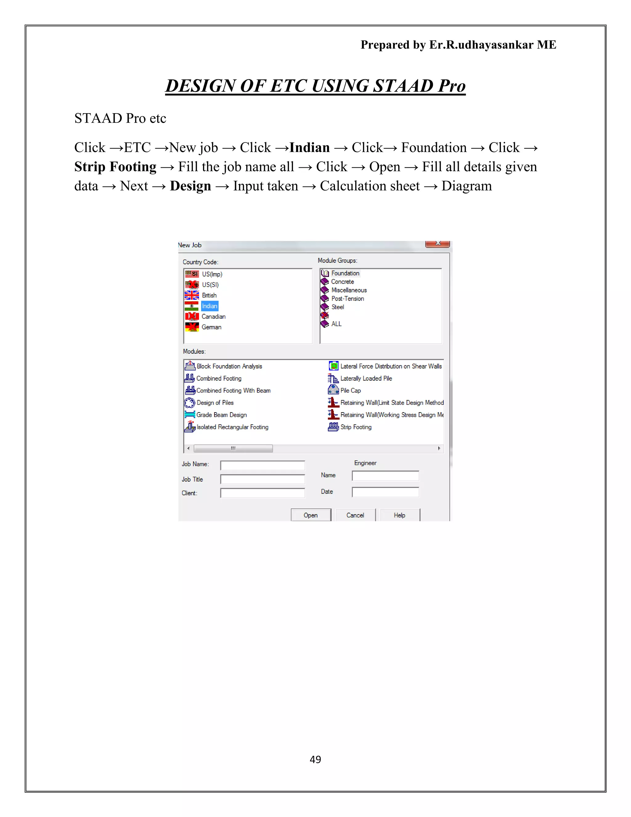
DESIGN OF FOUNATION USING STAAD Pro
Click → STAAD → Foundation
Open→ Staad foundation → Click → File new
Click→ [j] → New job → Write→ New job name→ Job title→ Isolated → Design
code→ Indian →Default unit→ SI → Ok
➢ Foundation Plan
➢ Load & Factor
➢ Design Parameter
➢ Cover Rebar
➢ Cover soil
➢ Geometry
➢ Design
➢ Design summary
➢ Footing layout
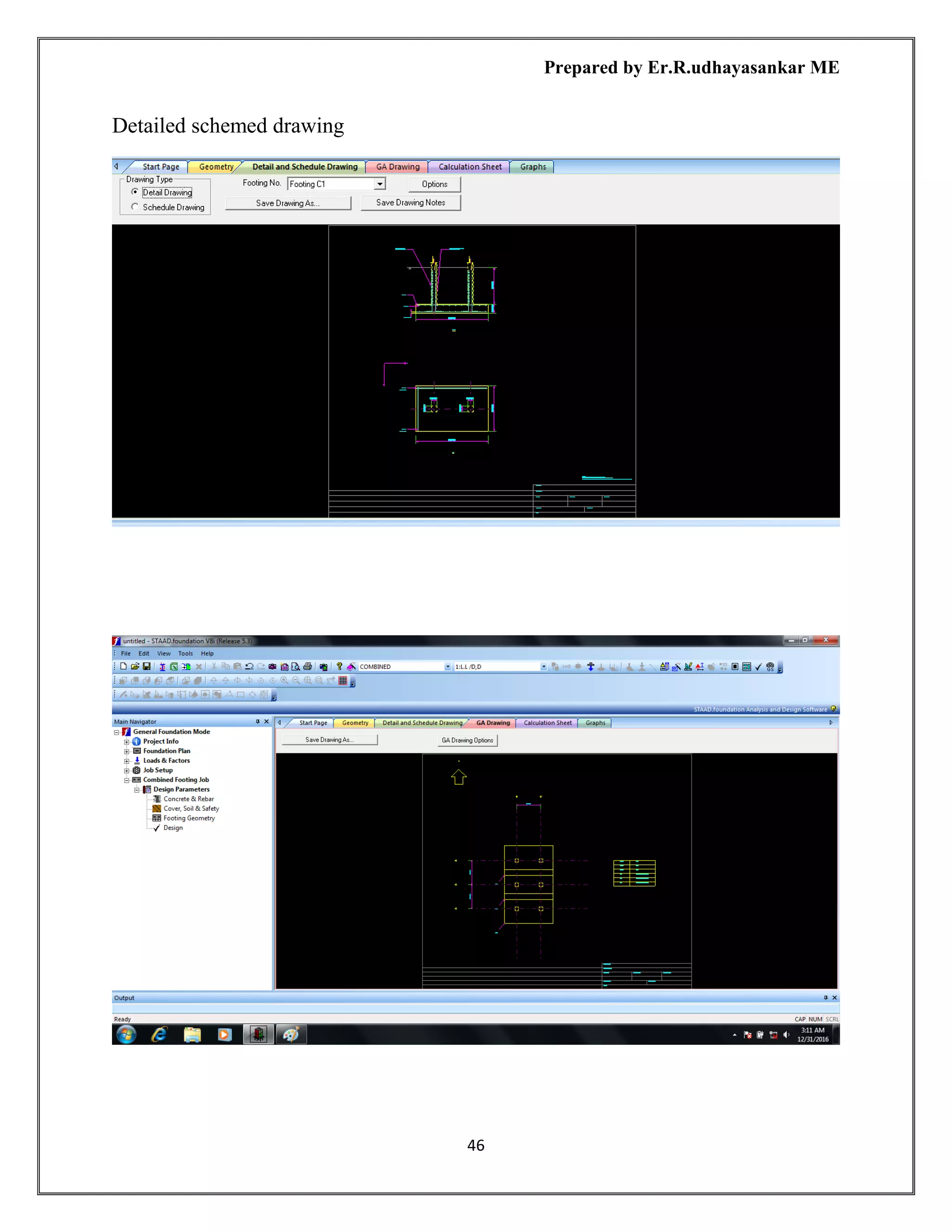
➢ Detailed drawing
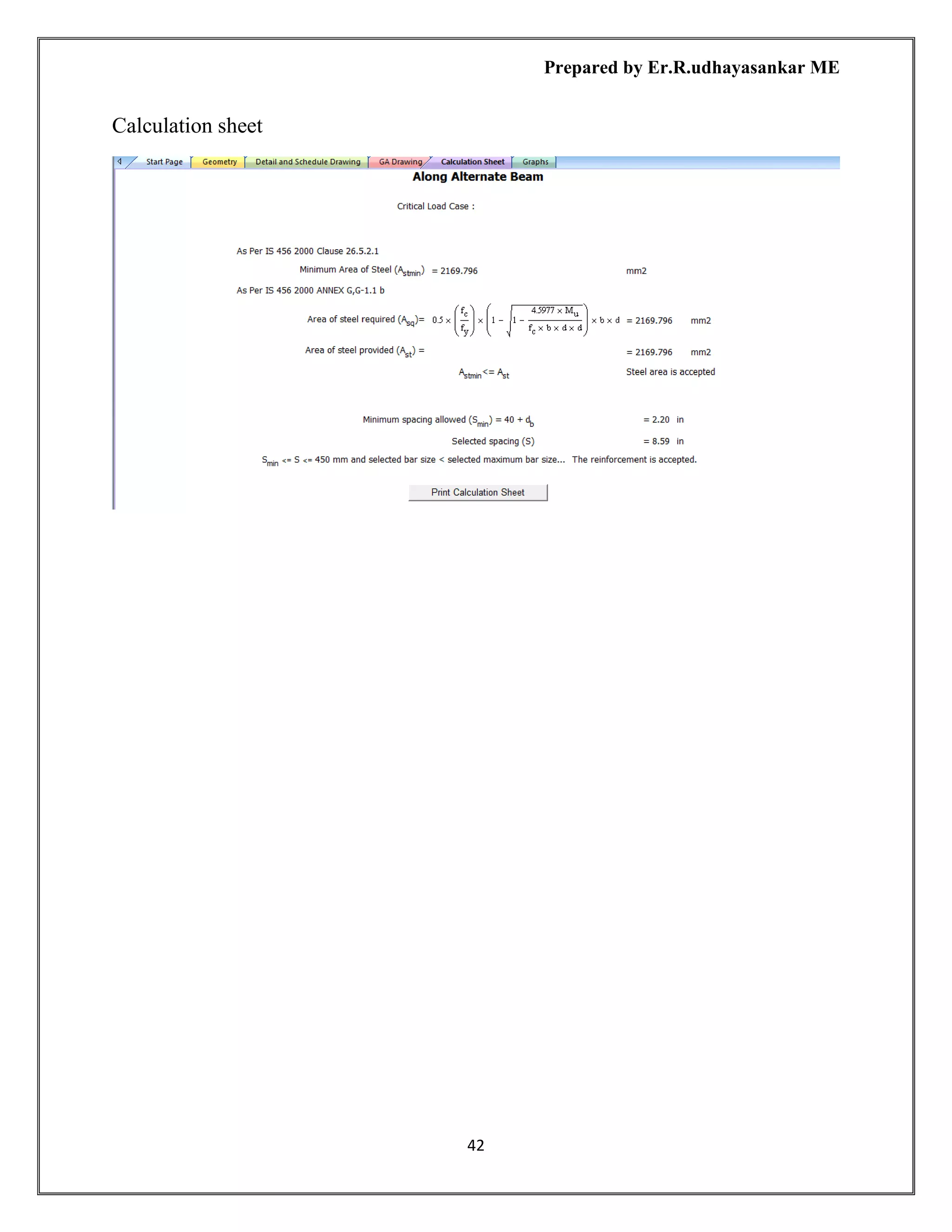
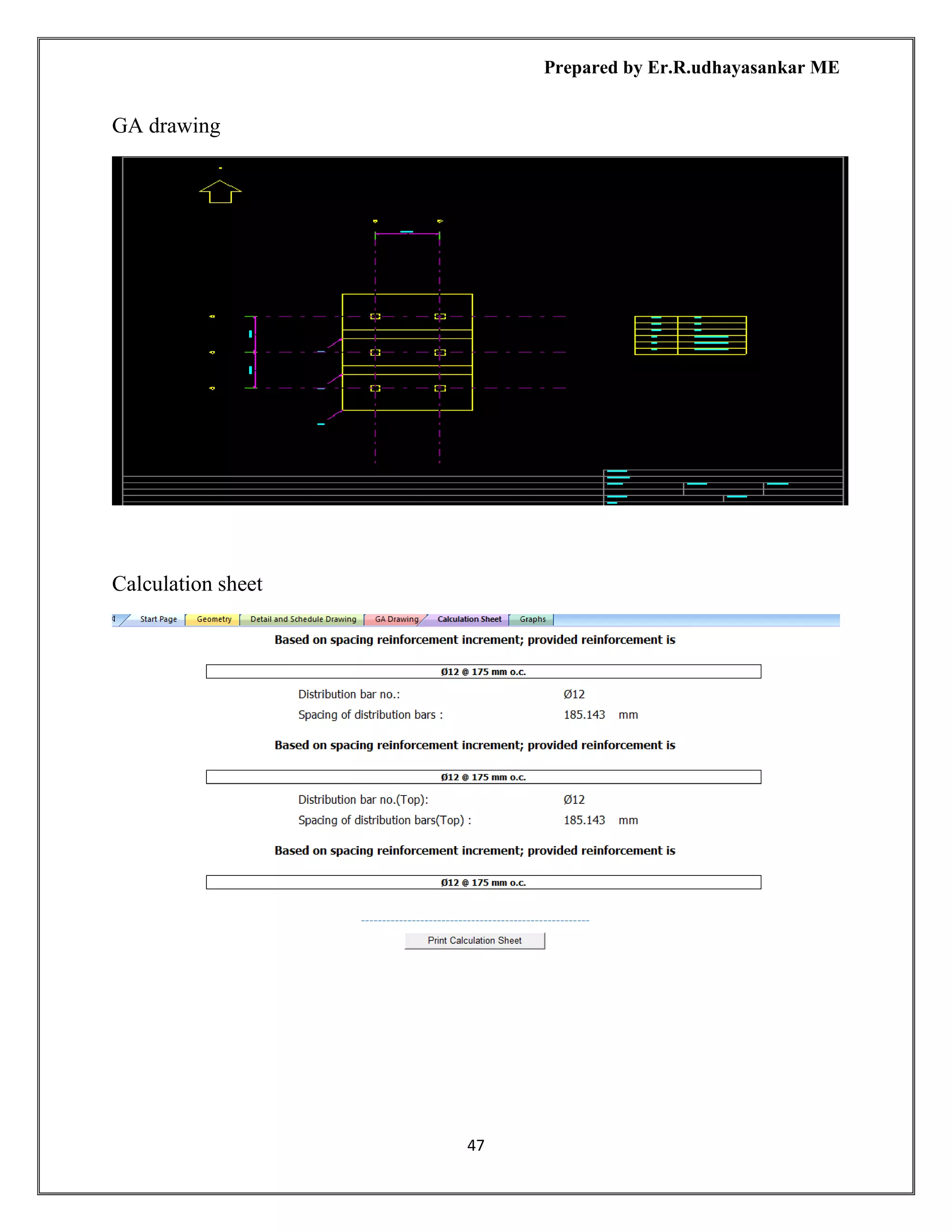
➢ Calculation sheet
Foundation plan
Click → tools → set out put units
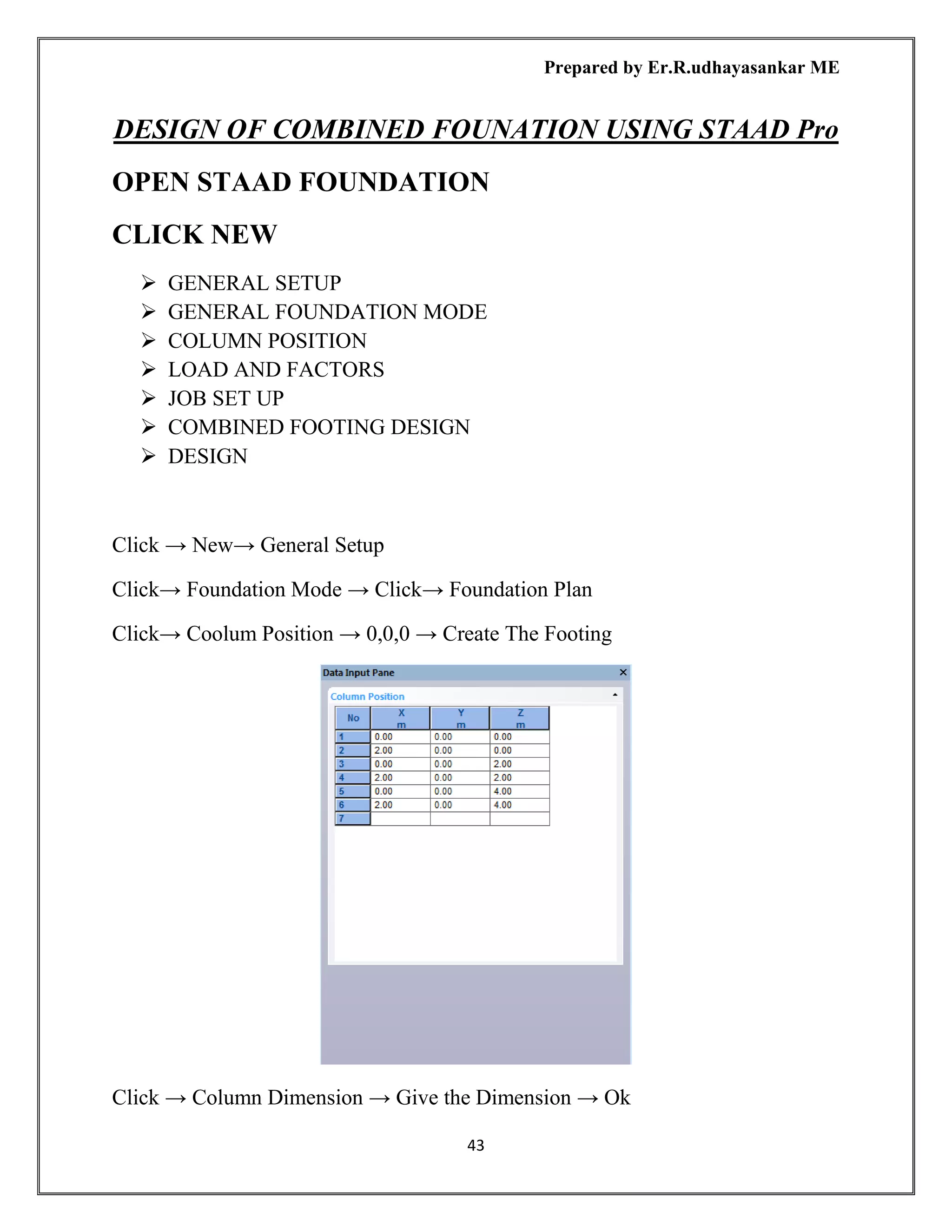
Click → Foundation Plan → Column position
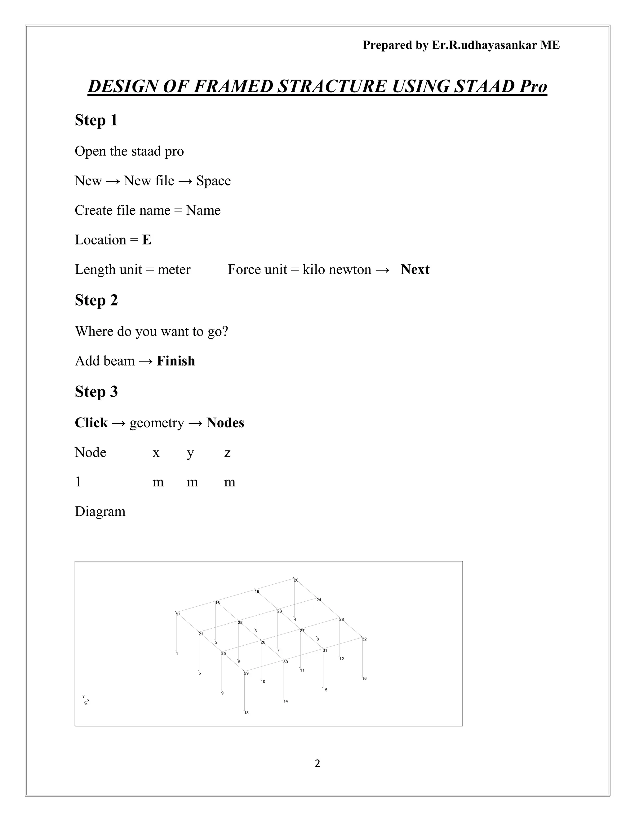
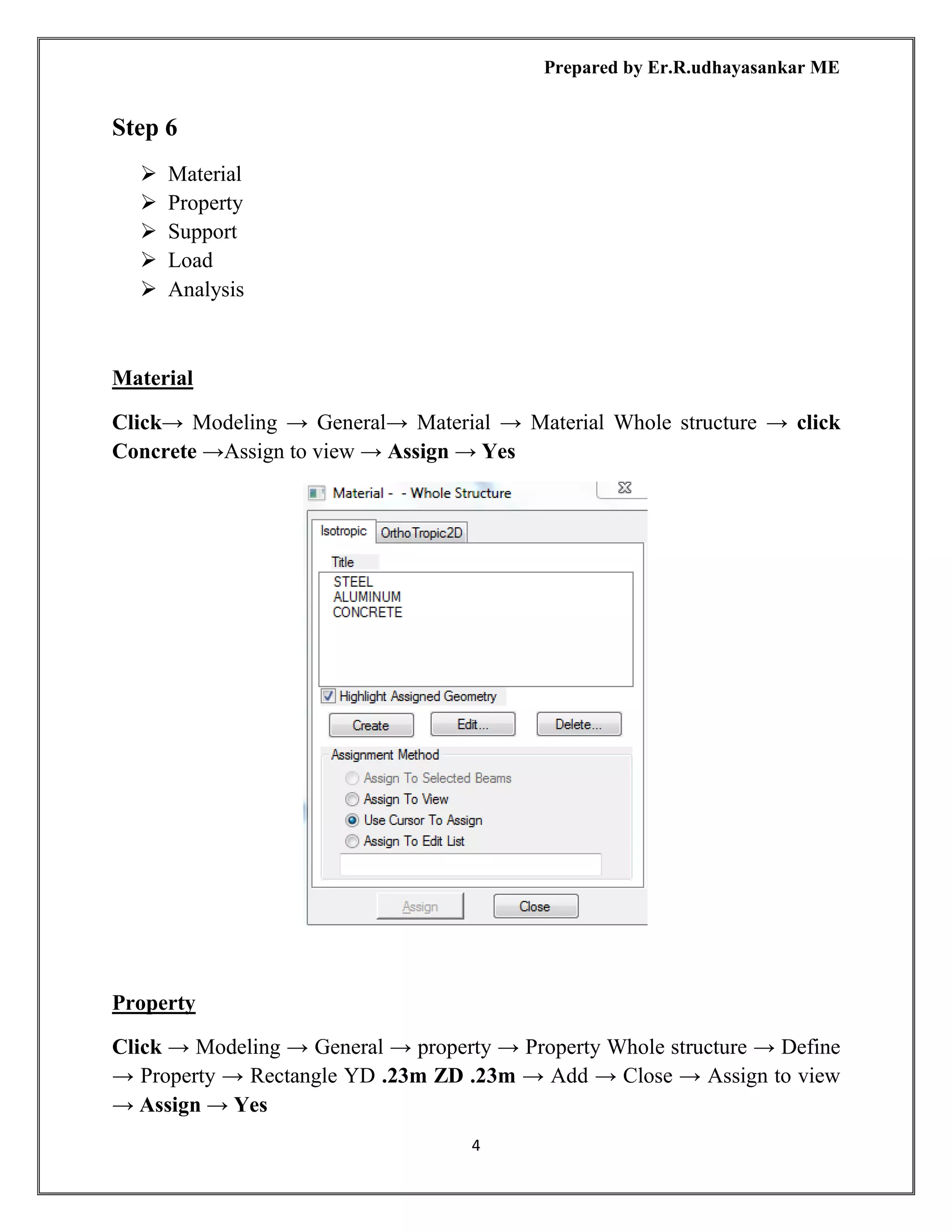
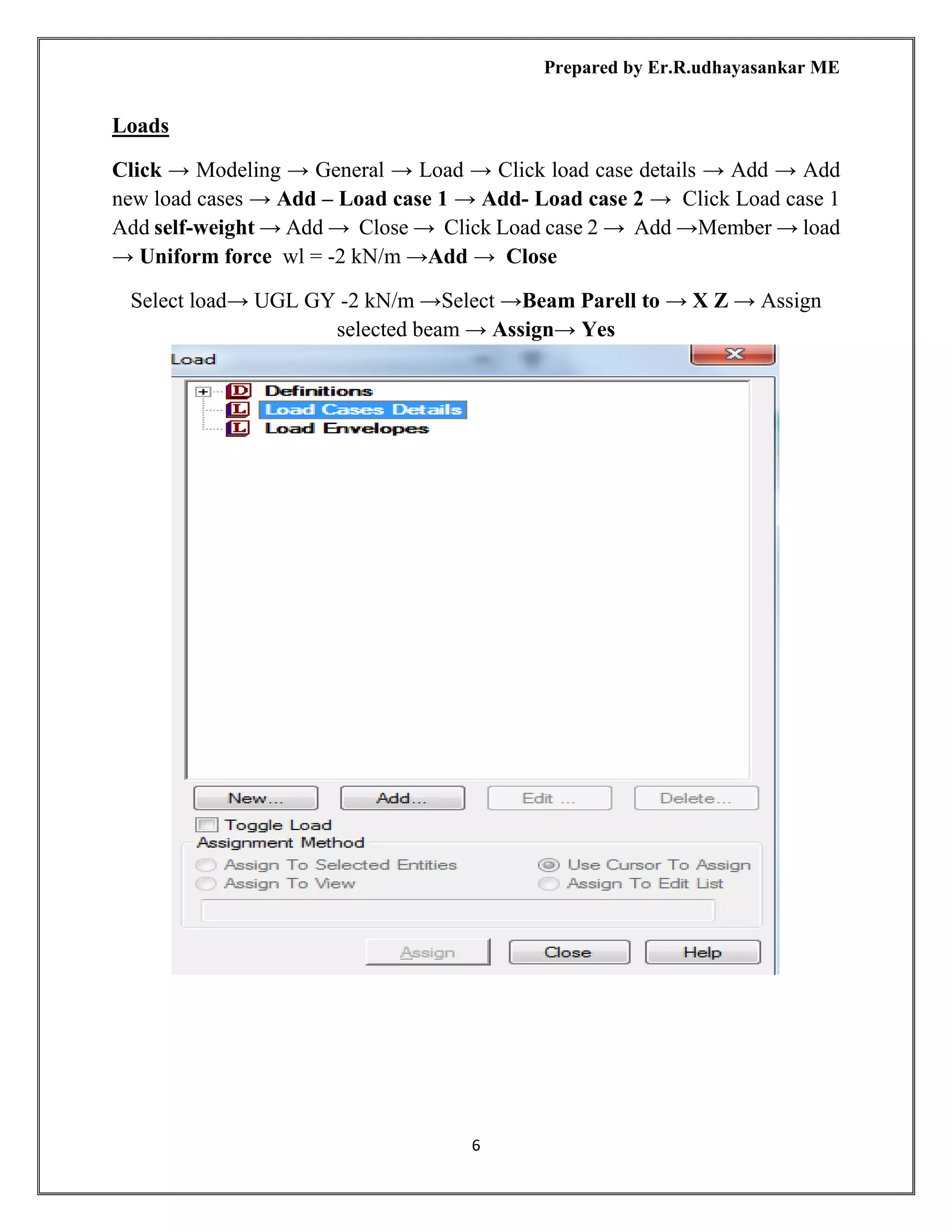
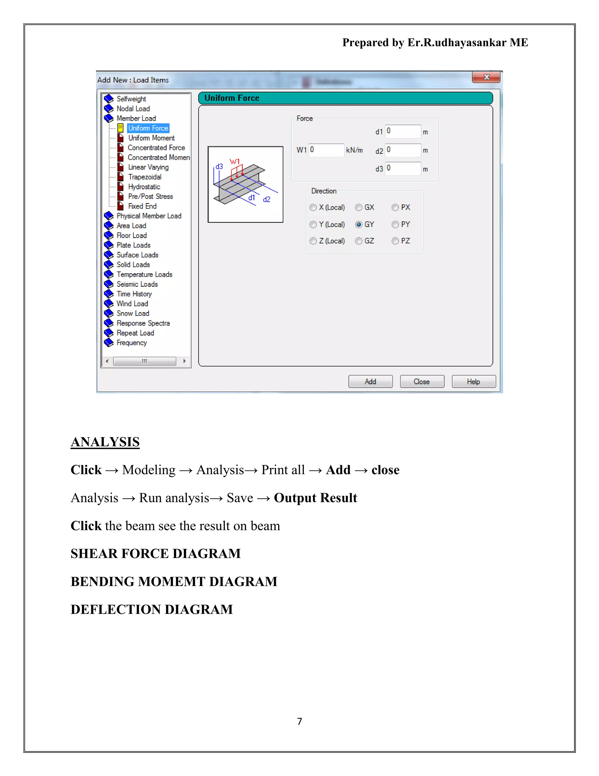
Click → Foundation Plan→ Column Dimension](https://image.slidesharecdn.com/staadpronotes-180714071542/75/Staad-pro-notes-32-2048.jpg)


The document is a comprehensive study material on using STAAD Pro for structural design, detailing procedures for modeling different structures such as framed structures, steel structures, plate slabs, foundations, and more. It includes step-by-step instructions on creating files, defining materials and properties, applying loads, performing analysis, and design processes for various components using the software. Additionally, it provides guidance on post-processing results and interpreting output for structural elements like beams, columns, and slabs.


