Download as PDF, PPTX


This document provides an introduction to internal combustion engines. It discusses key thermodynamic principles and defines different types of engines and heat engines. It also describes the basic components and operation of reciprocating internal combustion engines. The four main parts of a reciprocating IC engine are identified as the piston, connecting rod, crankshaft, and cylinder. The document further categorizes IC engines based on various factors such as application, basic design, fuel used, and cooling method. The working of four-stroke spark ignition and compression ignition engines is explained through diagrams. Finally, the document compares spark ignition and compression ignition engines.
Introduces the topic of Internal Combustion Engines (IC Engines) presented by Dr. S. Murali.
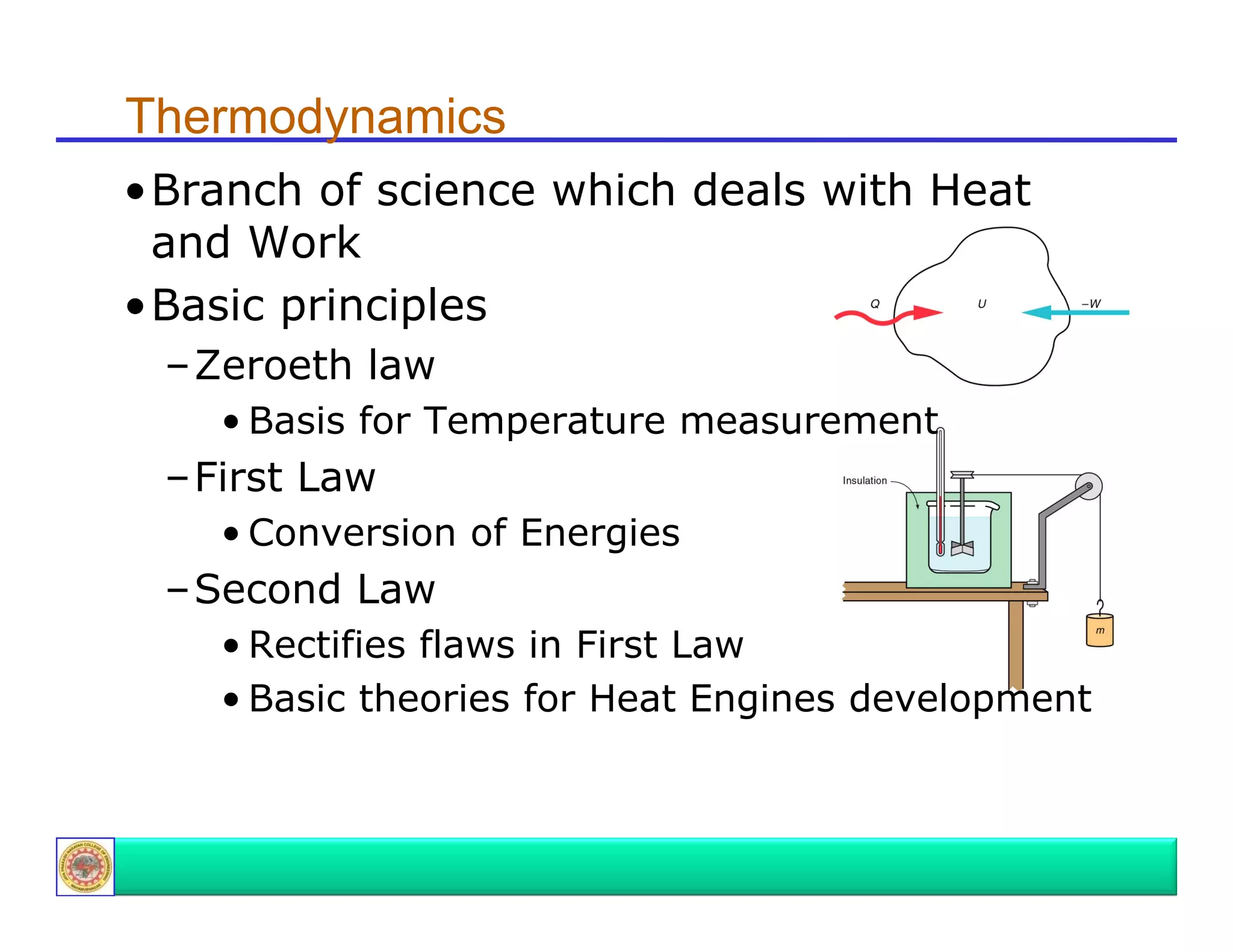
Discusses key thermodynamic laws essential for understanding heat and work in engines: Zeroeth, First, and Second Law.
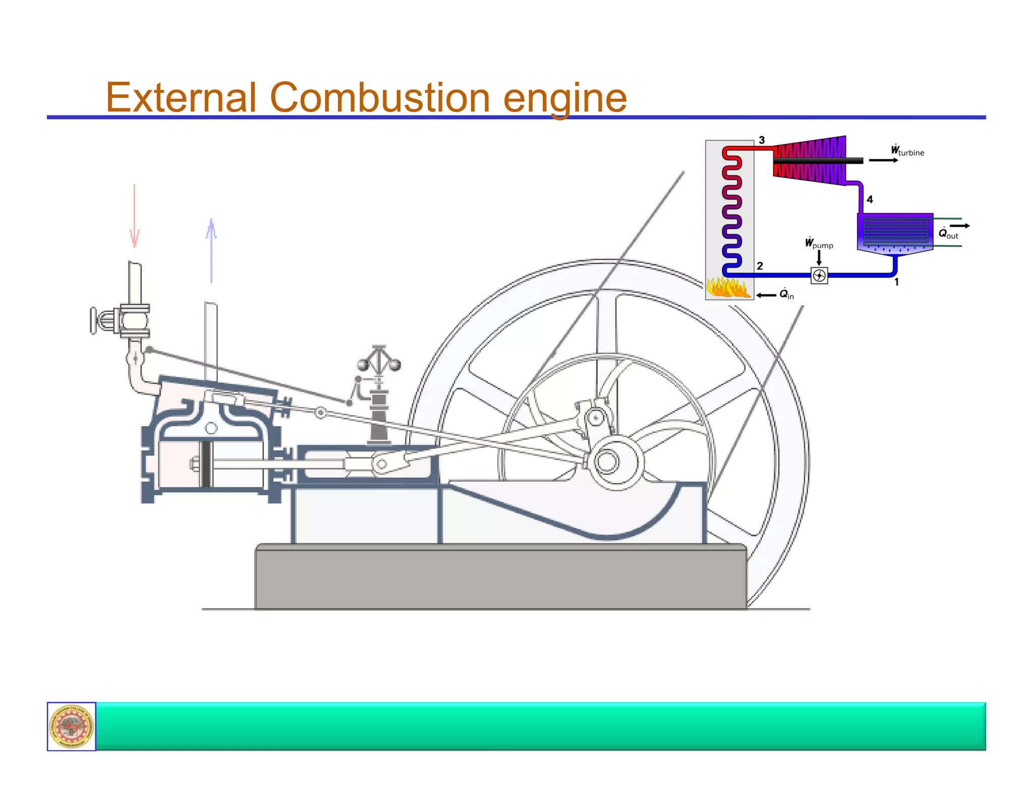
Defines engines as energy conversion devices and distinguishes between internal and external combustion engines.
Briefly highlights the two main types of combustion engines: Internal Combustion Engine (ICE) and External Combustion Engine.
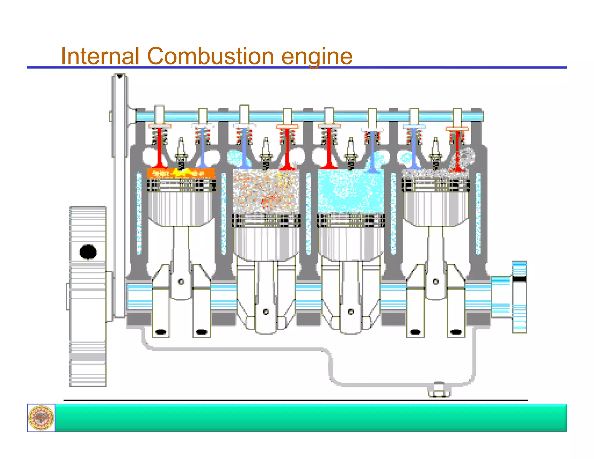
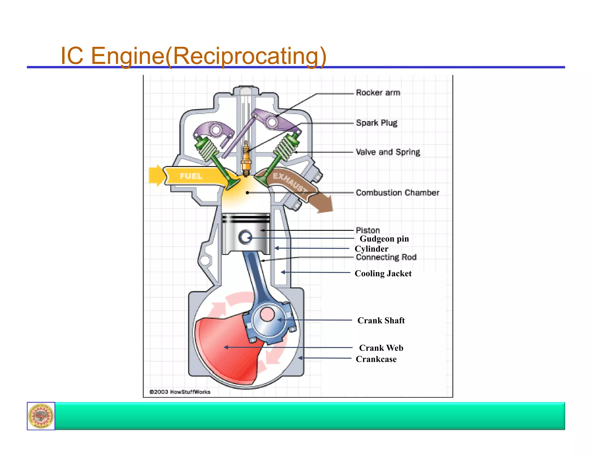
Describes essential parts of reciprocating IC engines including the cylinder, piston, crankshaft, and their functions.
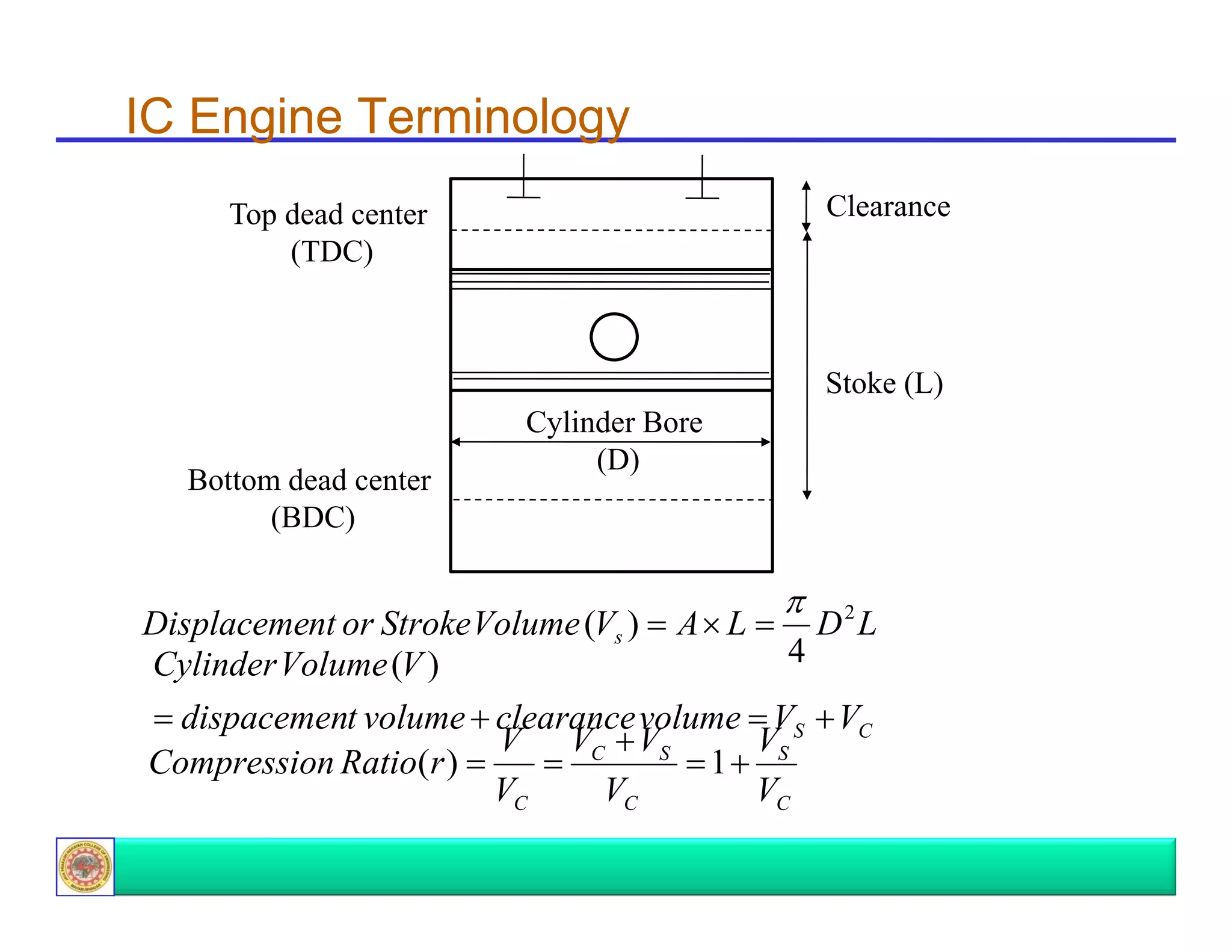
Introduces specific IC engine terminology including top dead center (TDC), bottom dead center (BDC), displacement, and compression ratio.
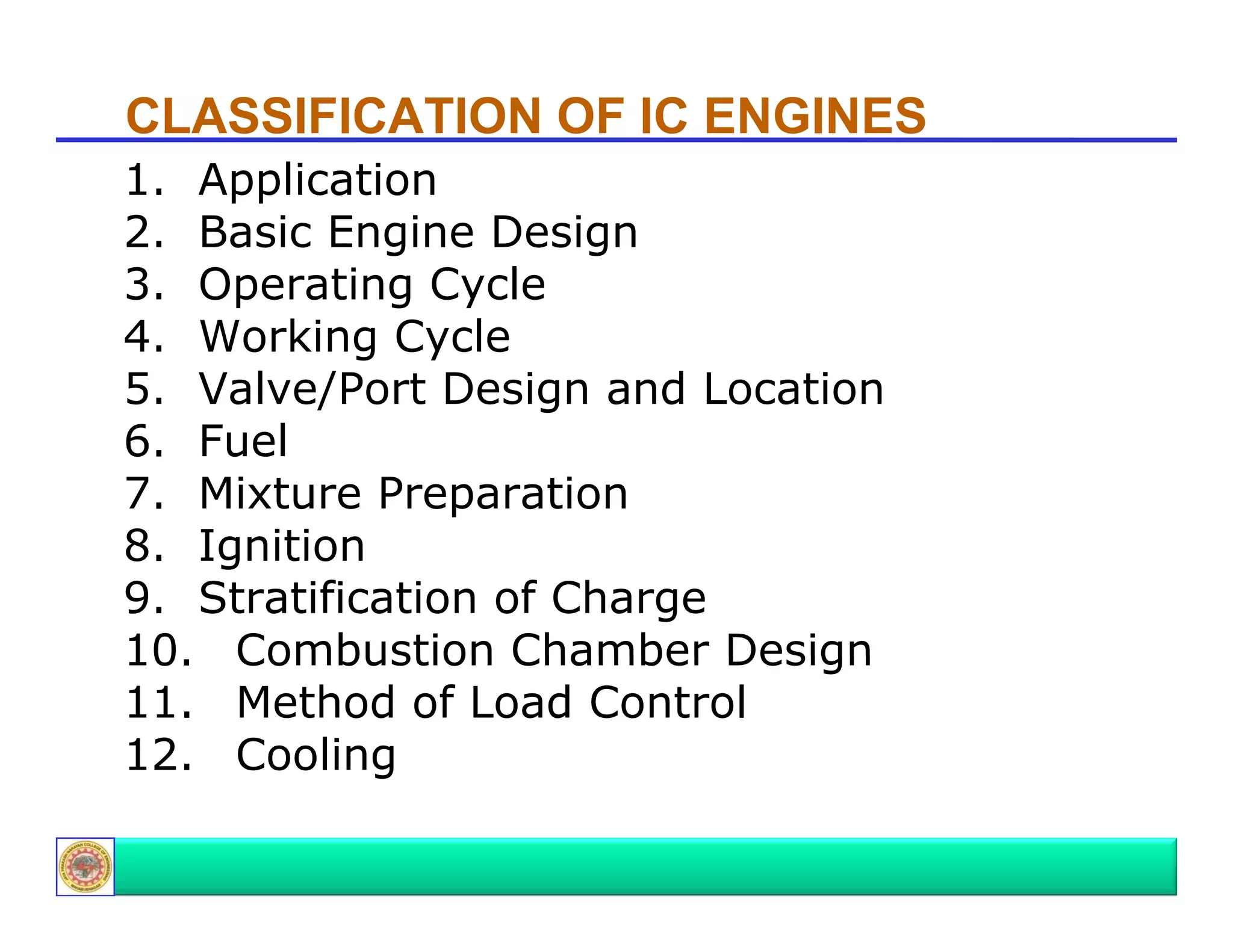
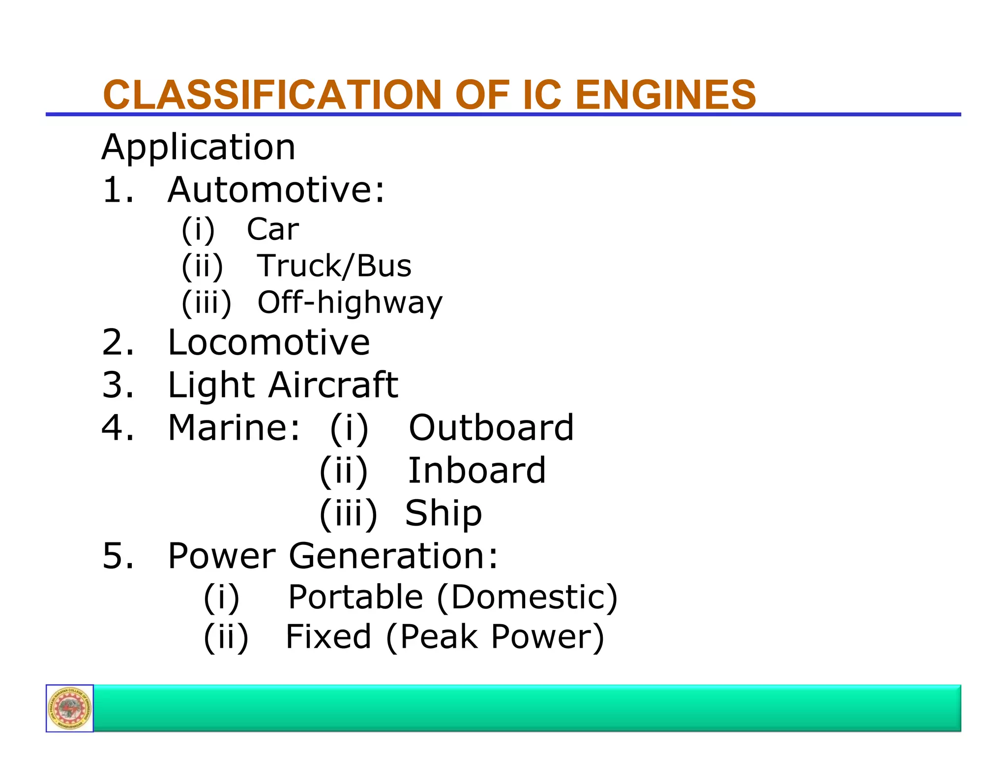
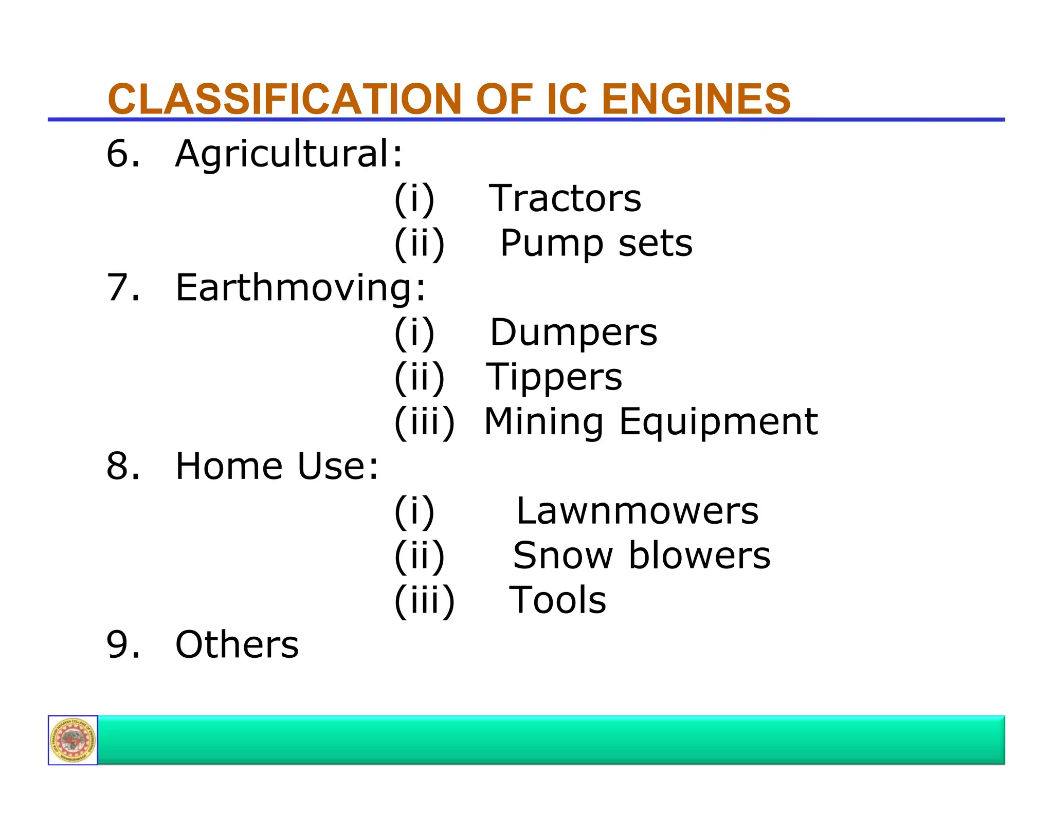
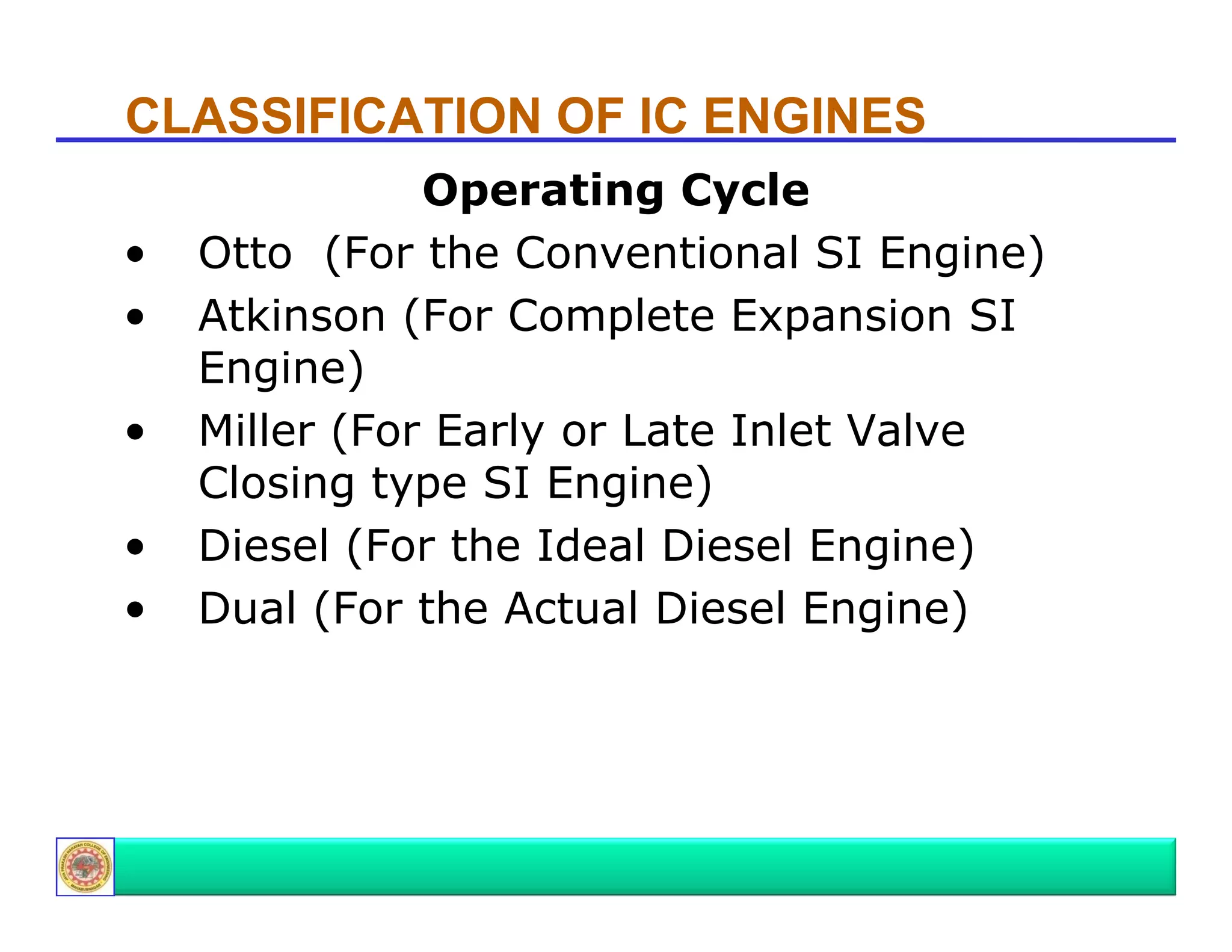
Details classifications based on application, basic design, operating cycles, and fuel types with examples.
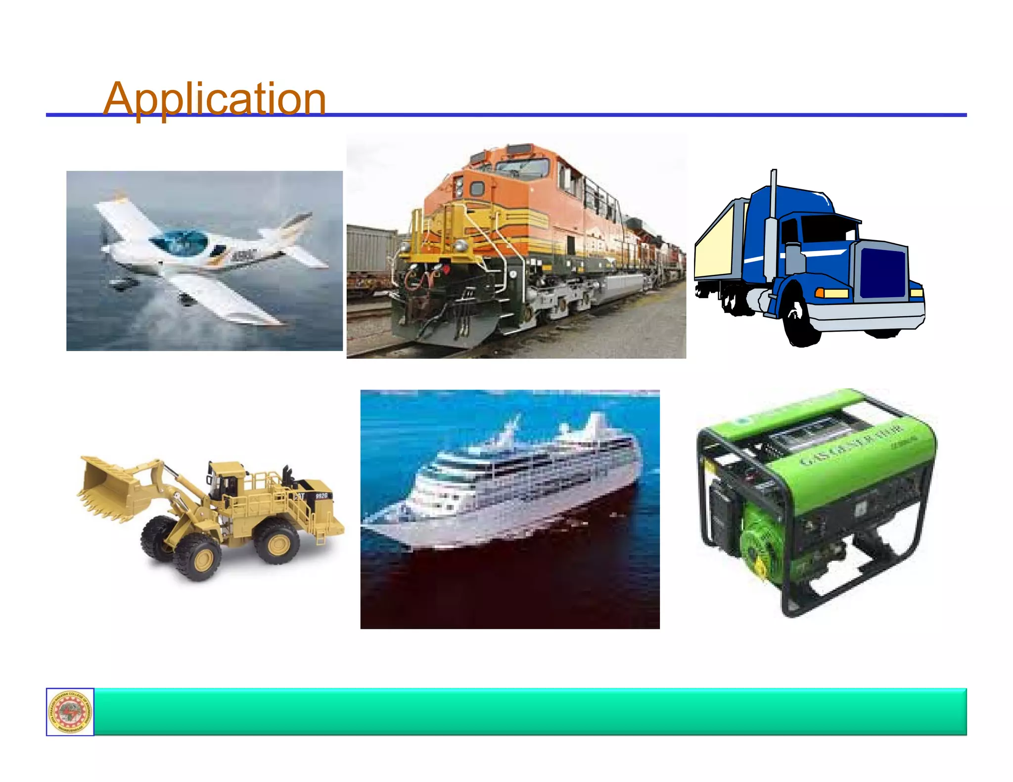
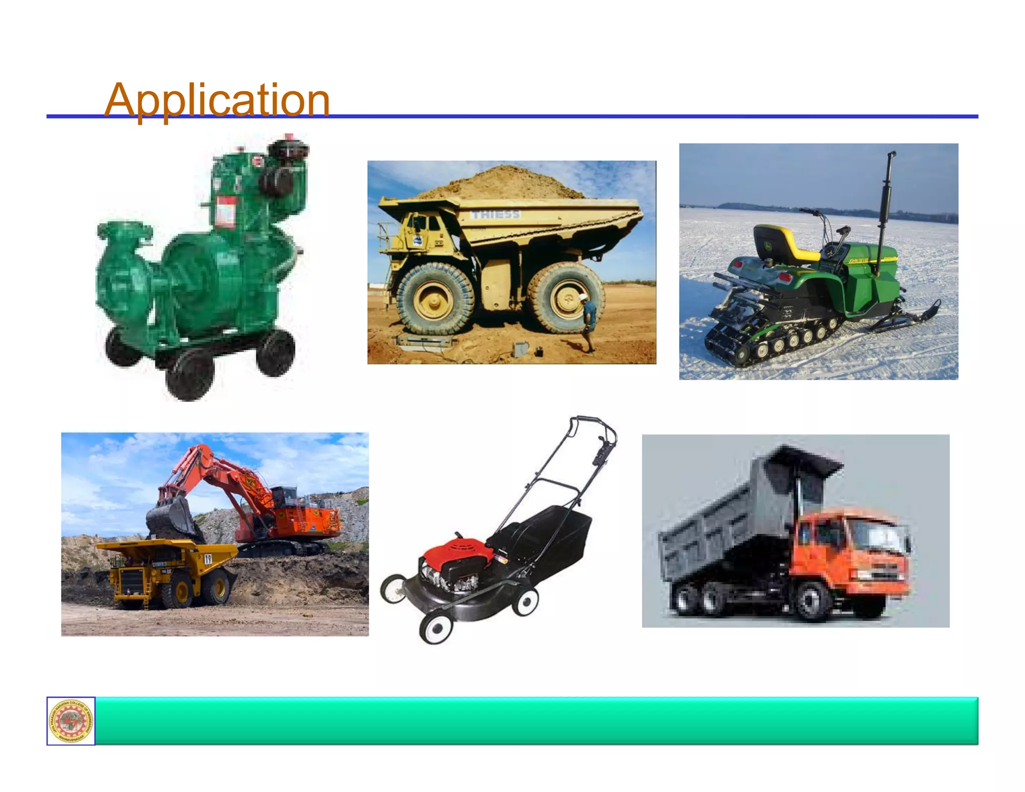
Continues classifications highlighting various applications of IC engines beyond automotive, including agricultural and marine.
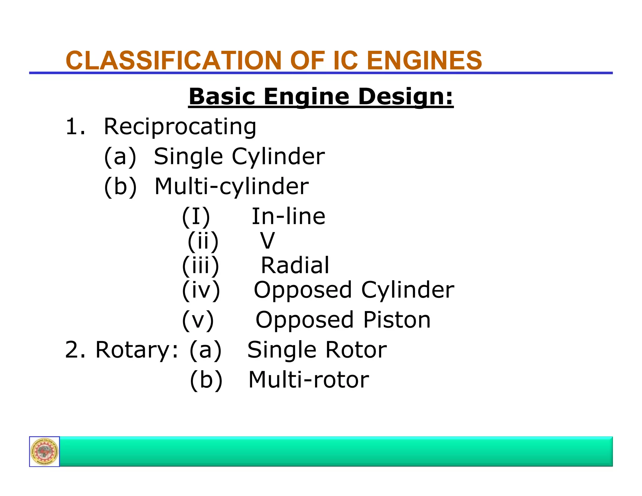
Focuses on applications like agriculture, home use, and various designs of engines such as rotary and reciprocating.
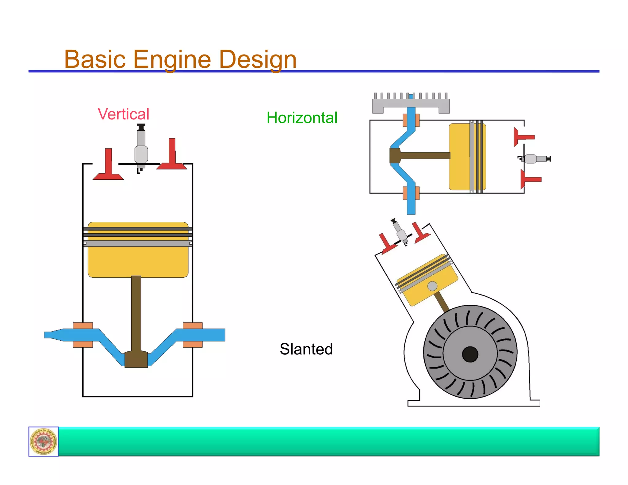
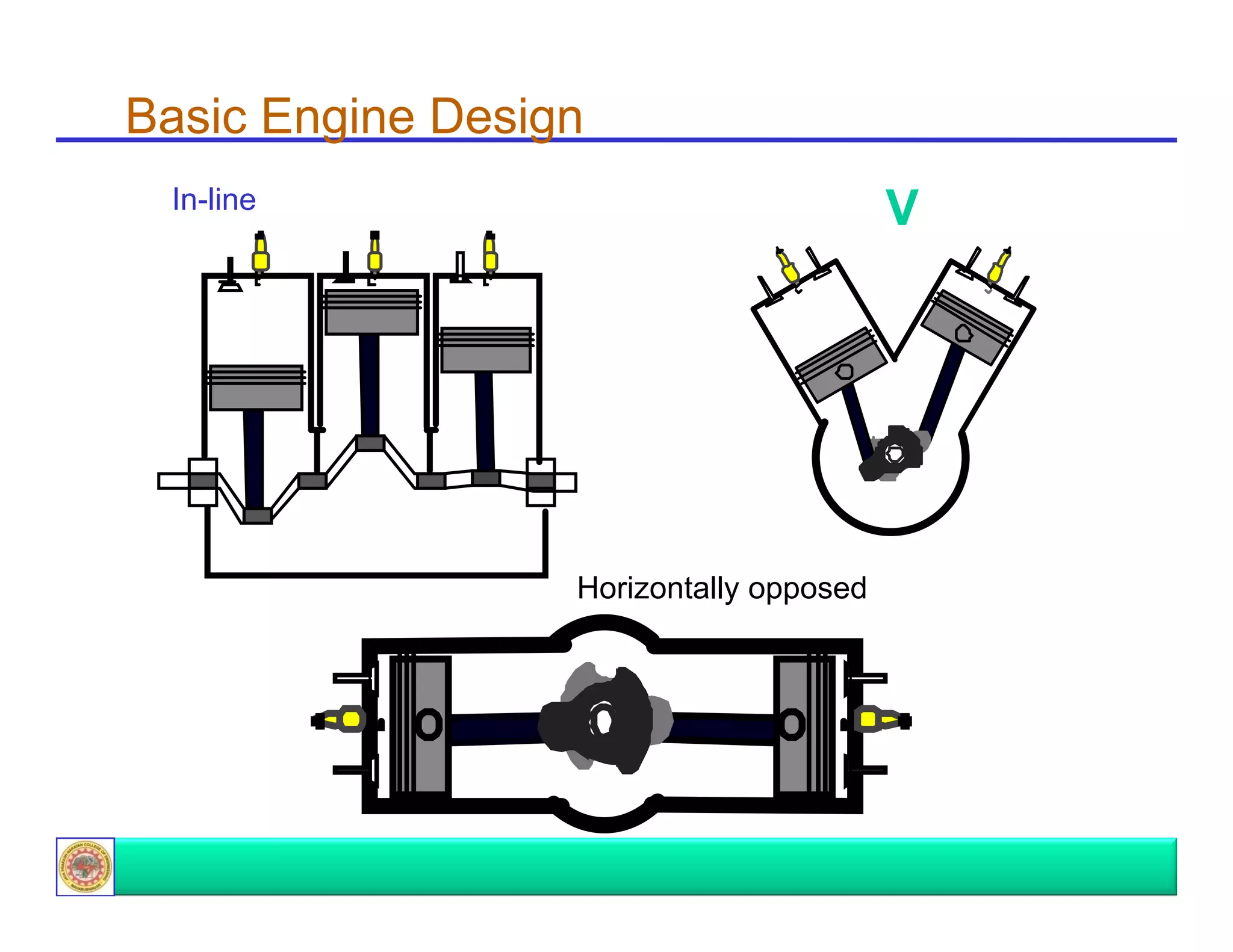
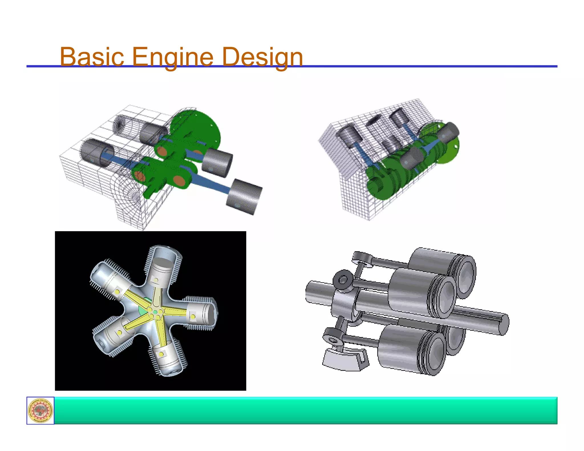
Discusses basic engine designs, operating cycles including Otto, Diesel, and Dual cycles.
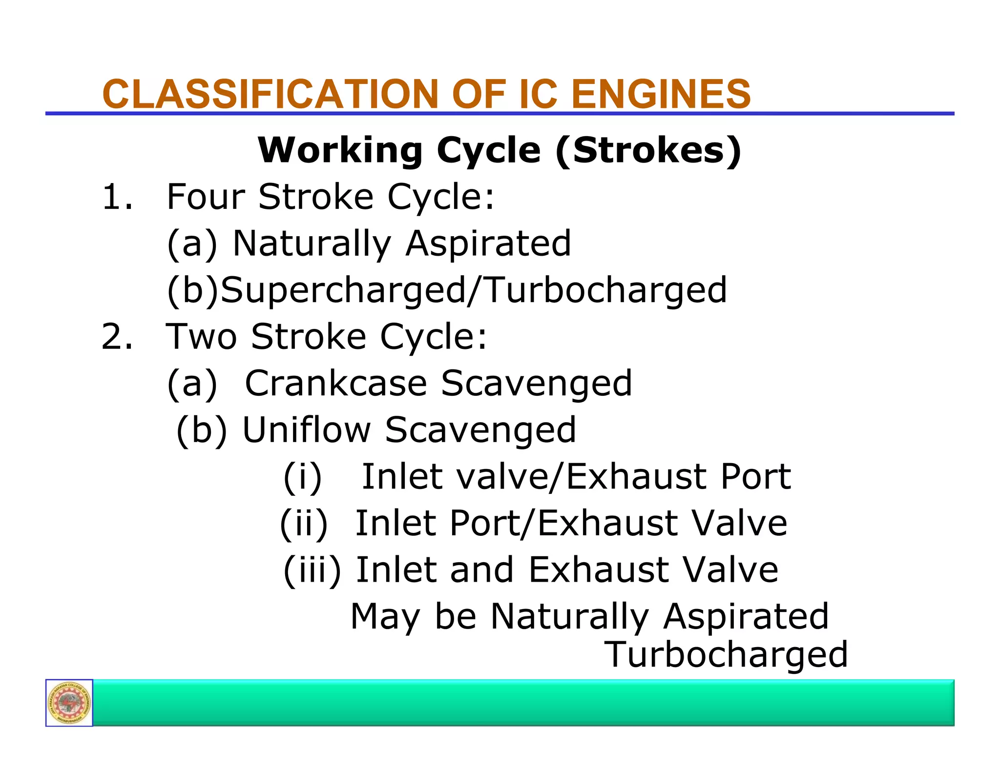
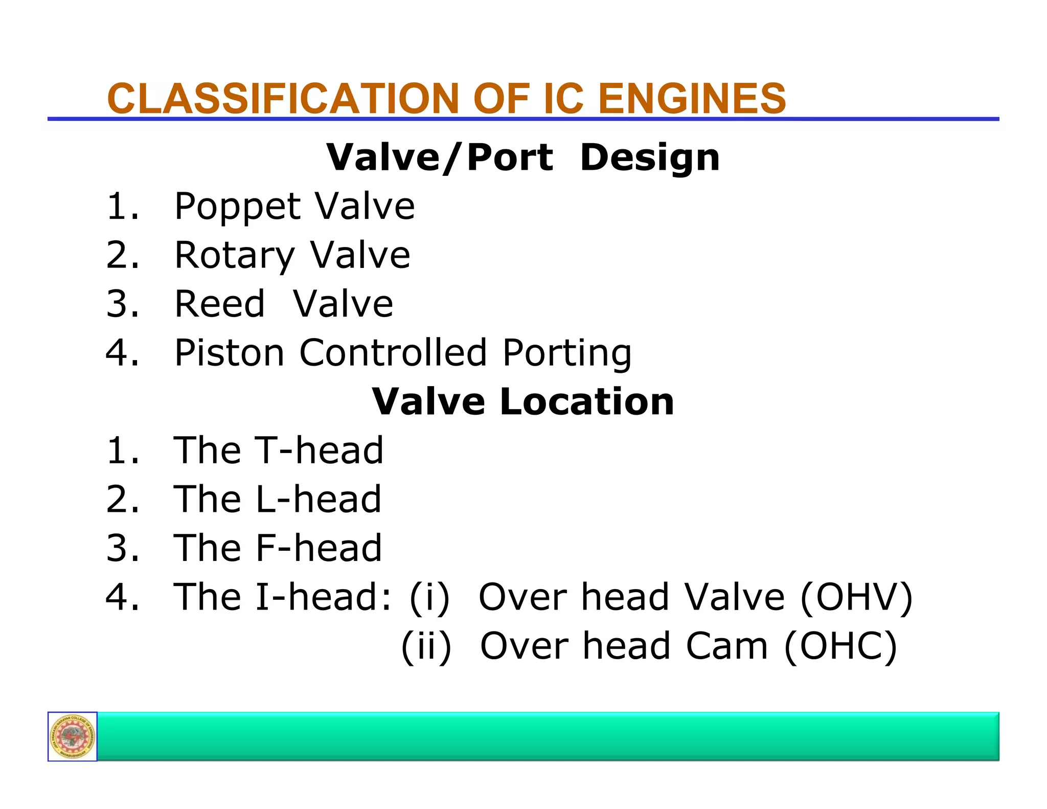
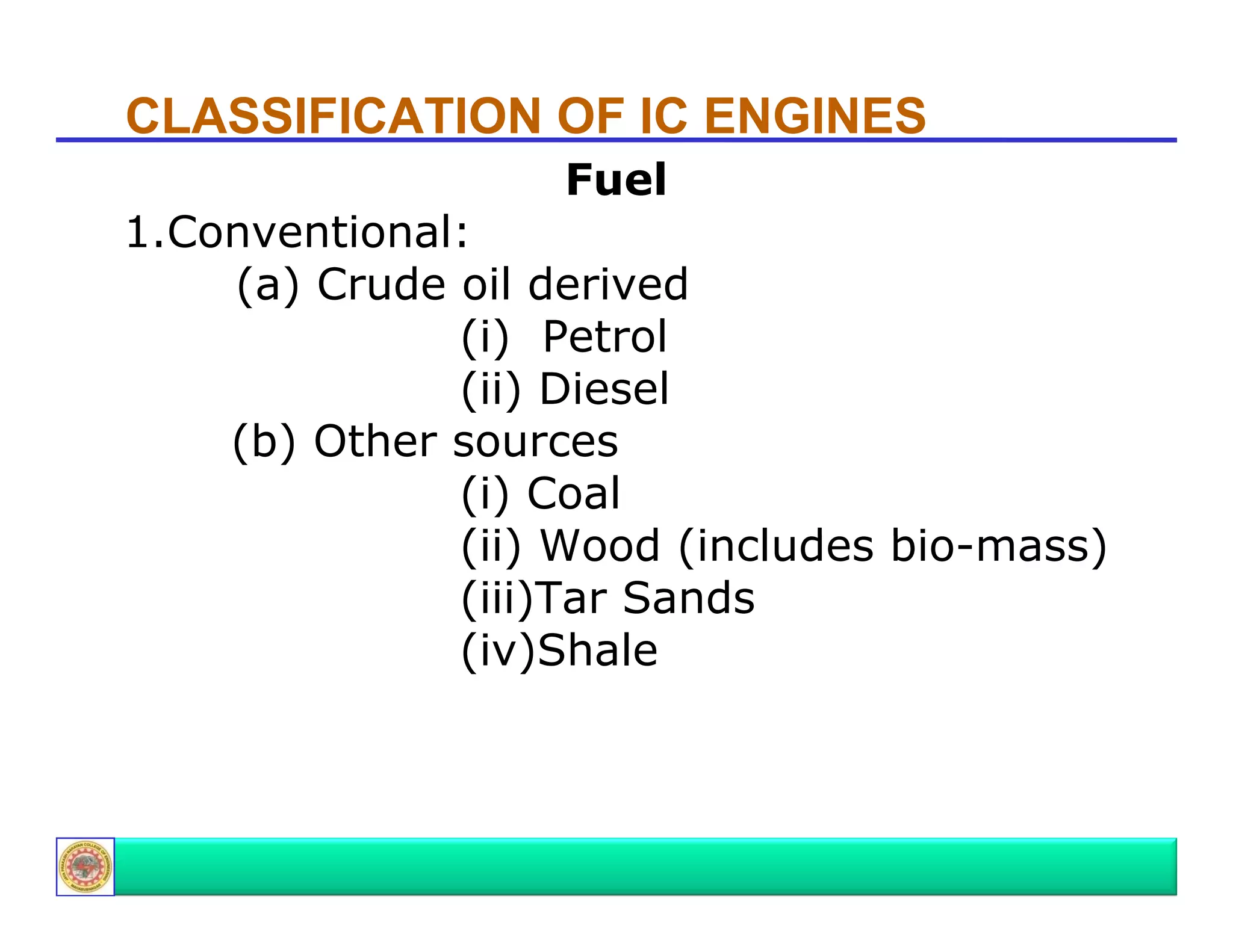
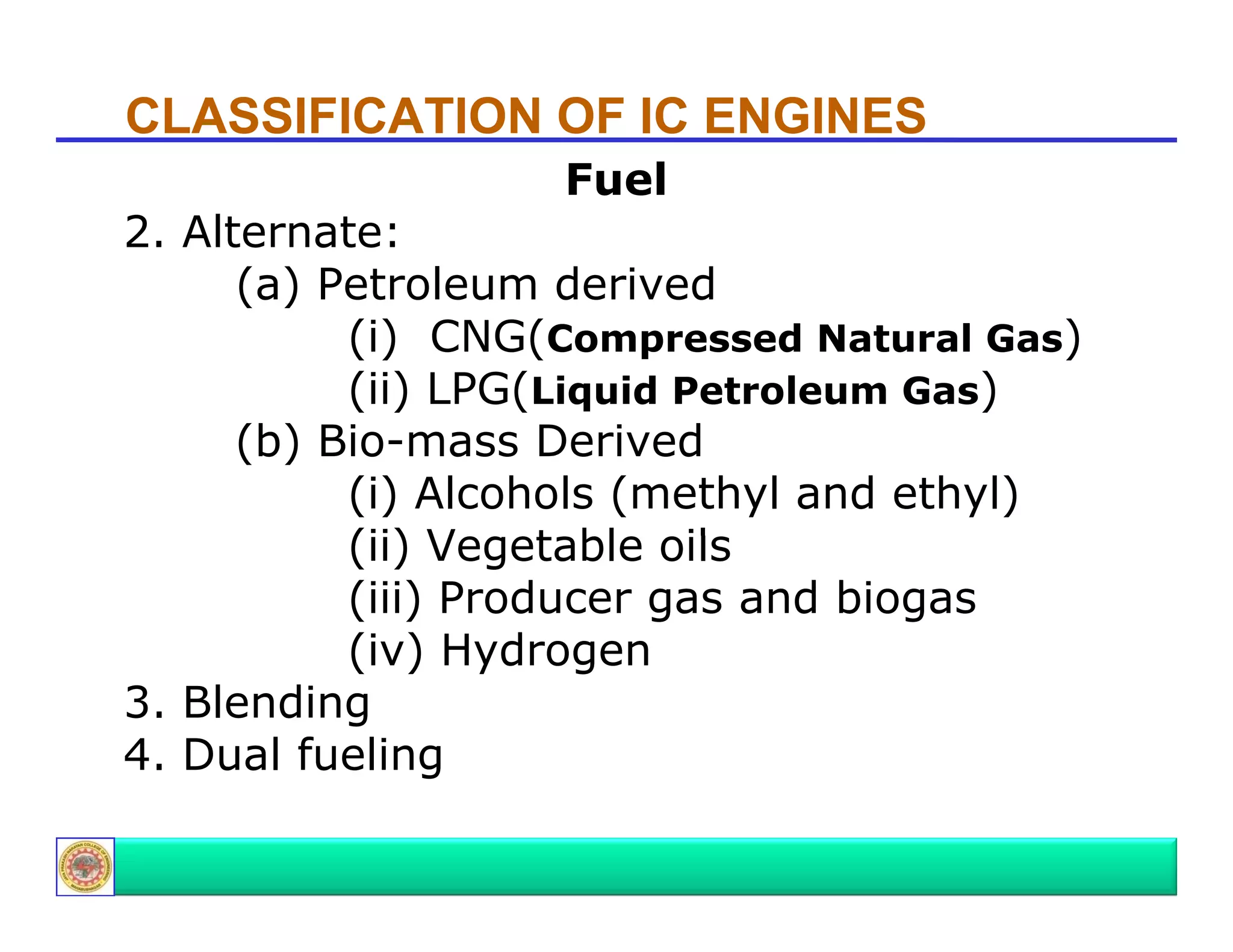
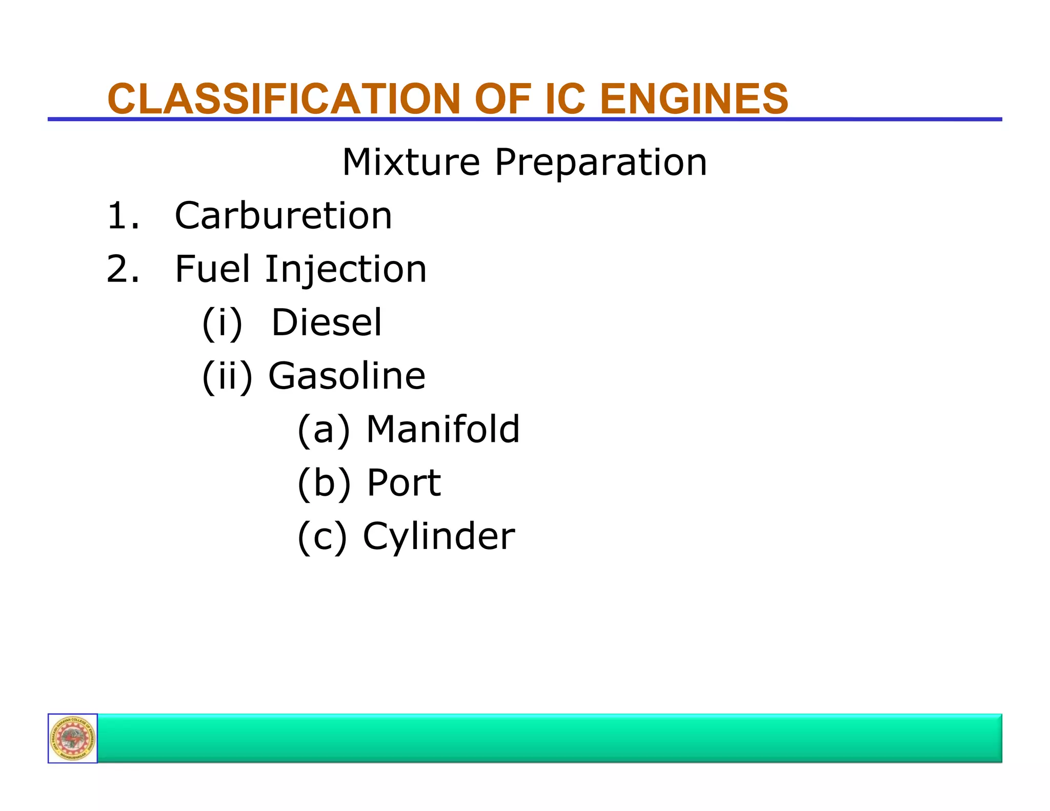
Explains working cycles (4-stroke and 2-stroke), valve design, fuel types (conventional and alternate), and mixture preparation.
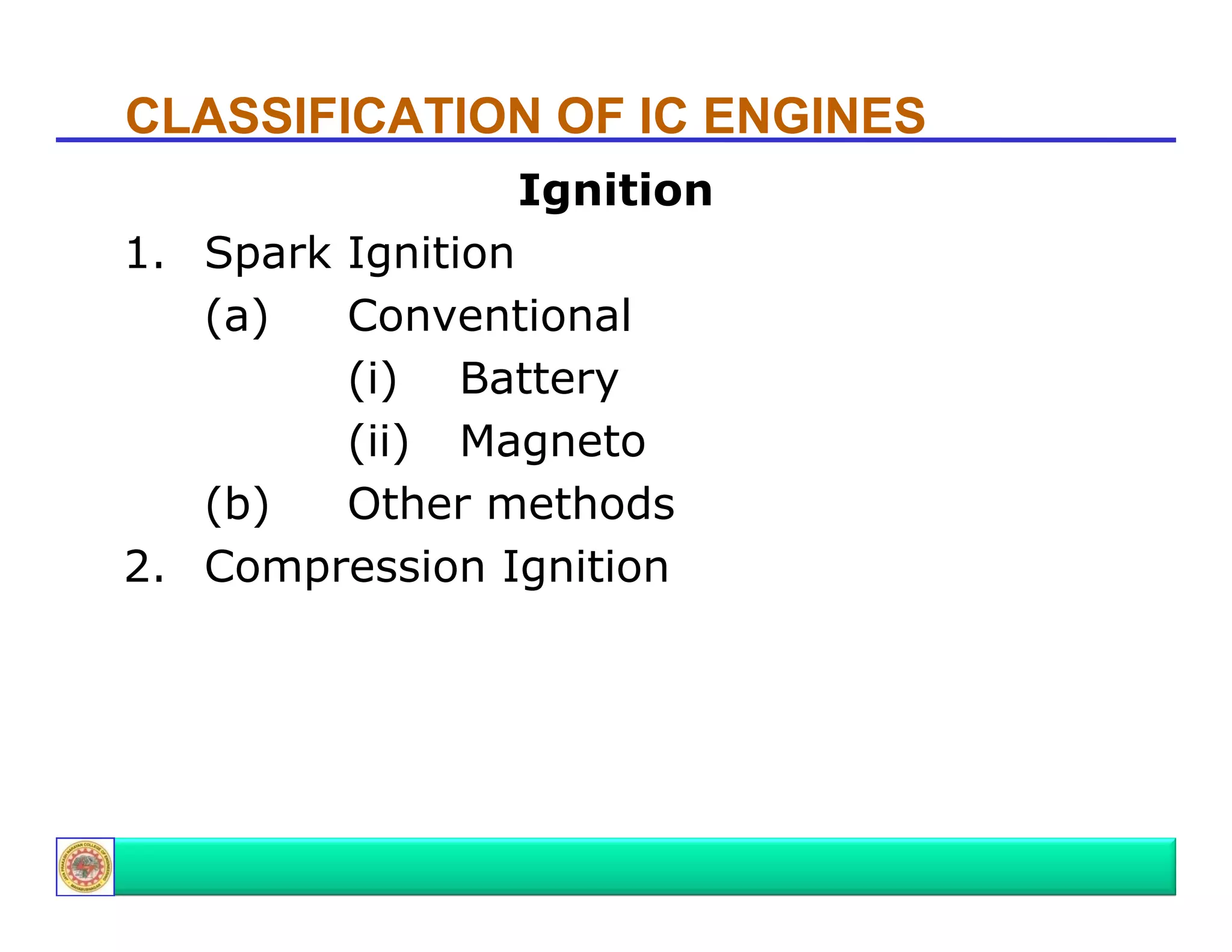
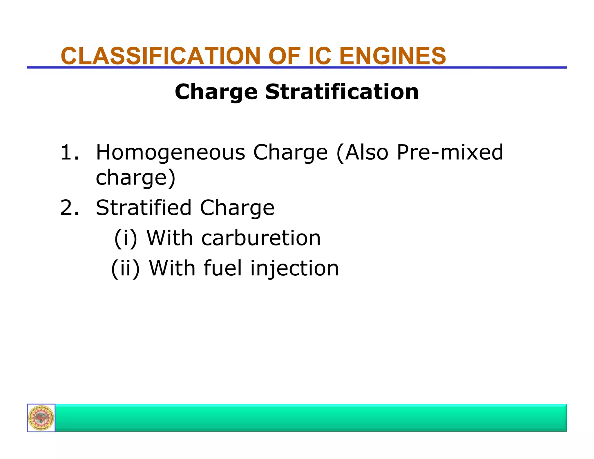
Describes ignition systems used in IC engines, including spark ignition and compression ignition, and charge stratification.
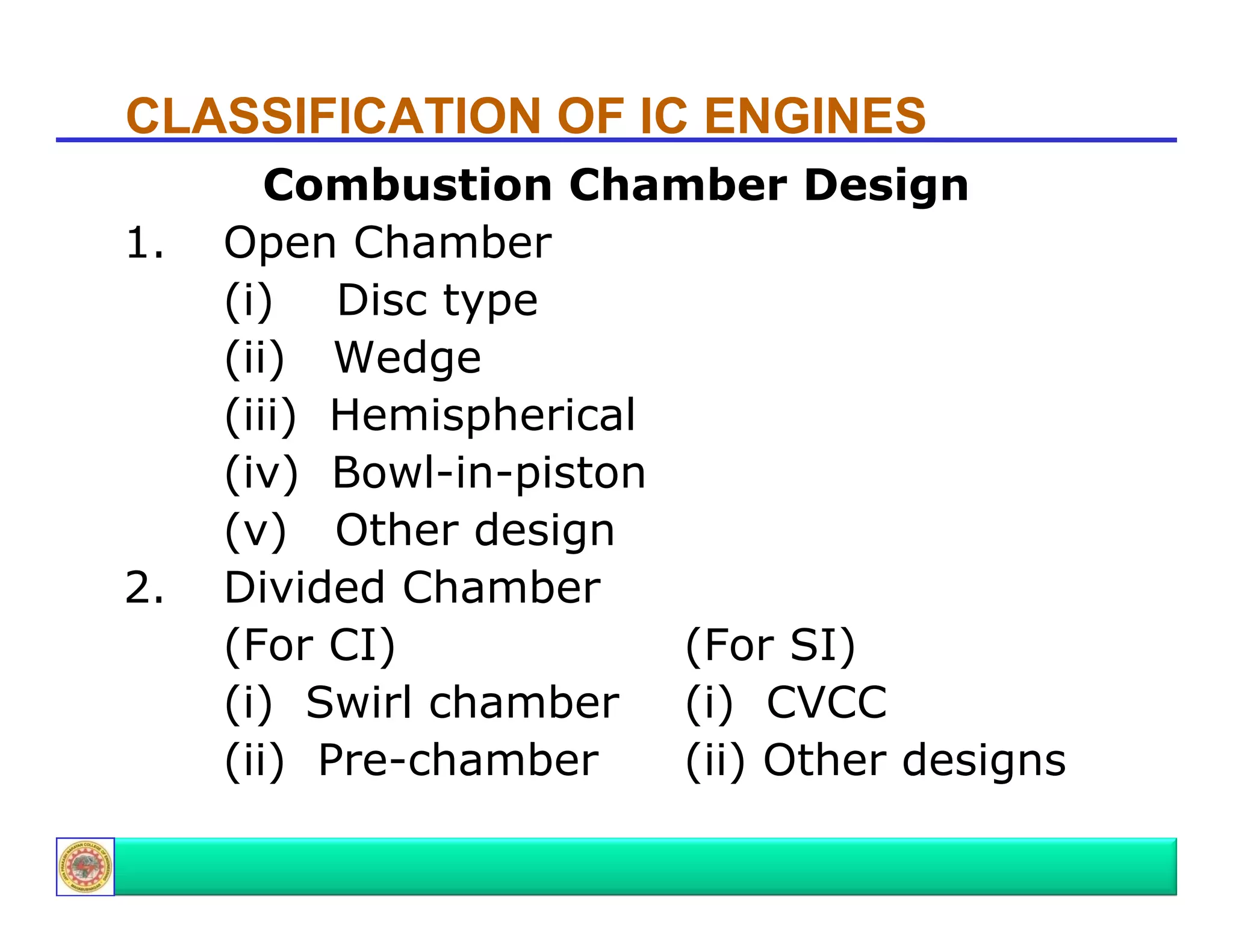
Discusses different designs of combustion chambers for SC and CI engines focusing on their configurations.
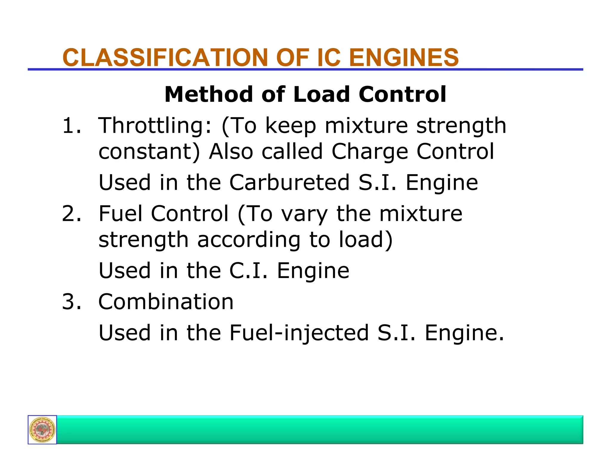
Explains methods of controlling engine load, including throttling and fuel control methods, alongside cooling mechanisms.
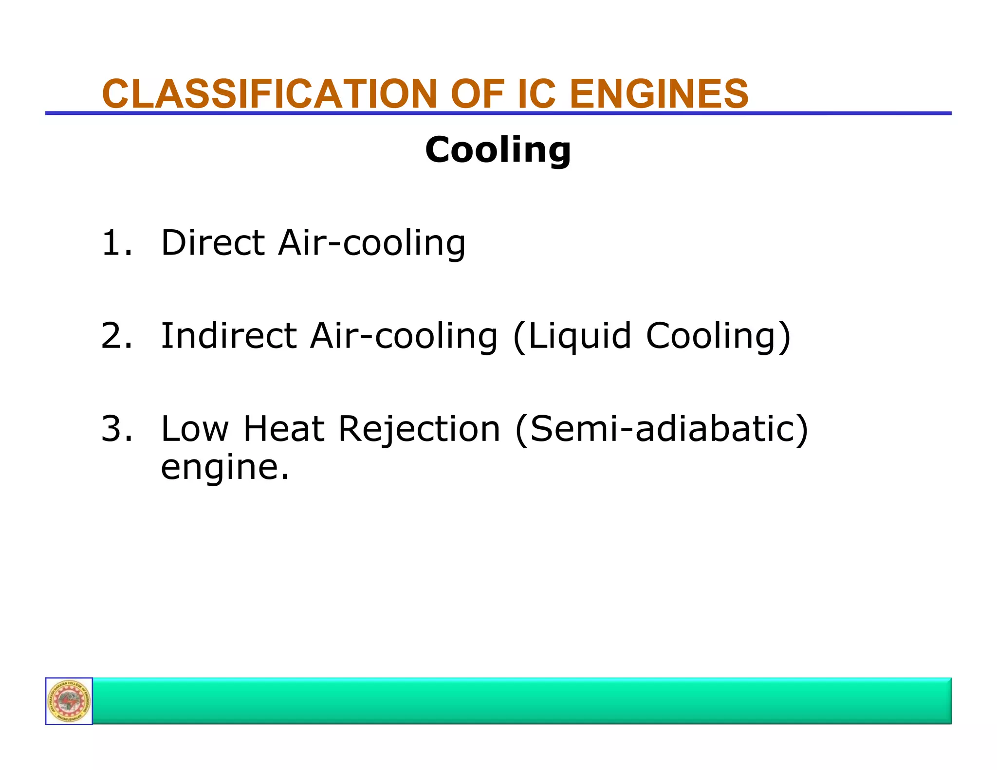
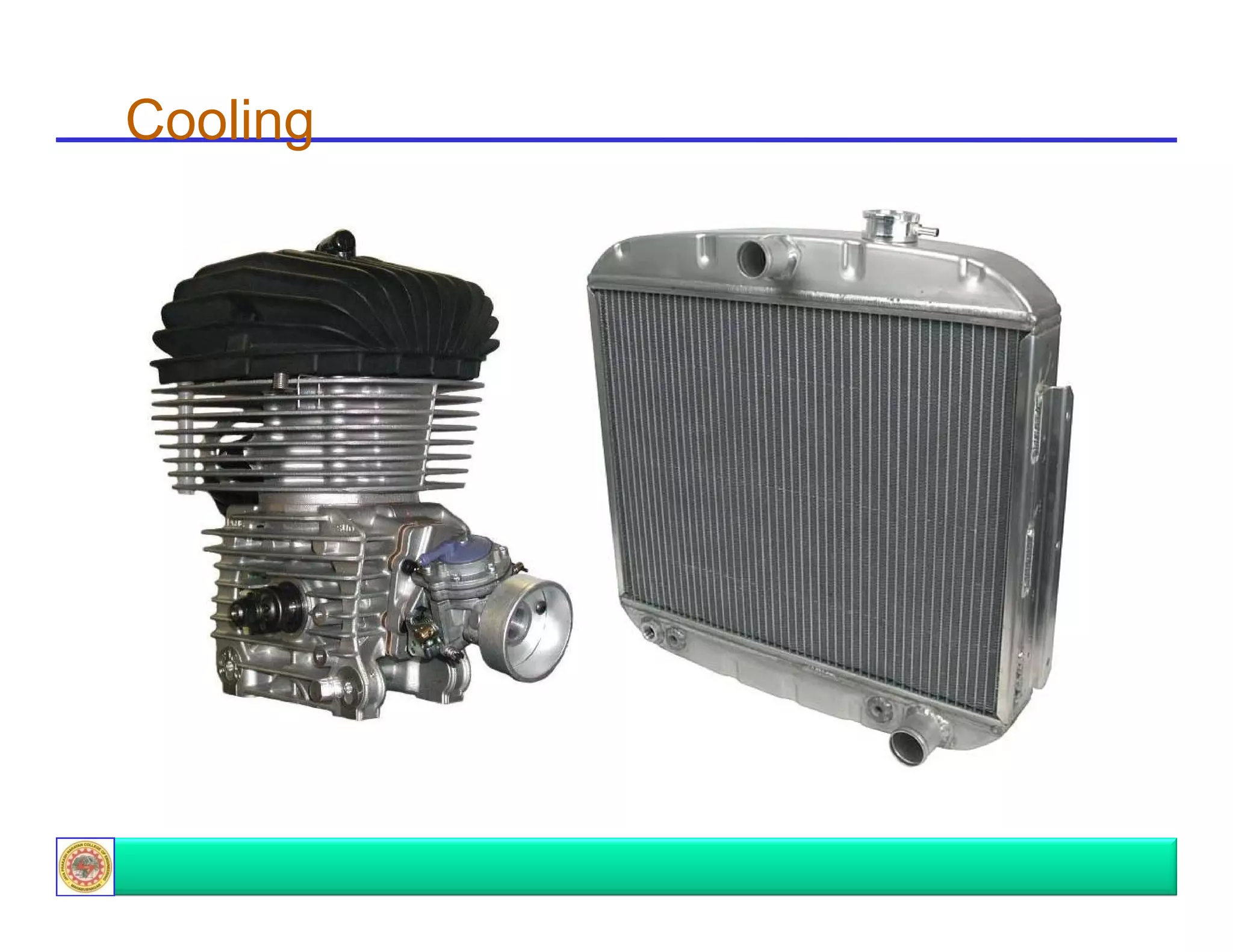
Details various cooling methods applicable for IC Engines including direct air-cooling and liquid-cooling.
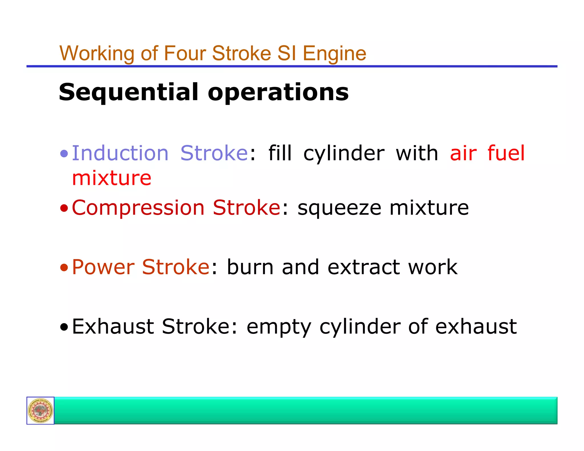
Introduces the sequential operations of a four-stroke SI engine, including induction, compression, power, and exhaust strokes.
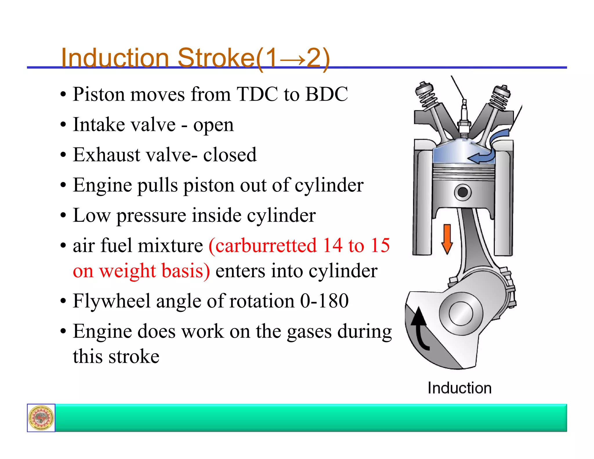
Details induction stroke mechanics in a four-stroke SI engine, outlining the piston movement and air-fuel mixture entry.
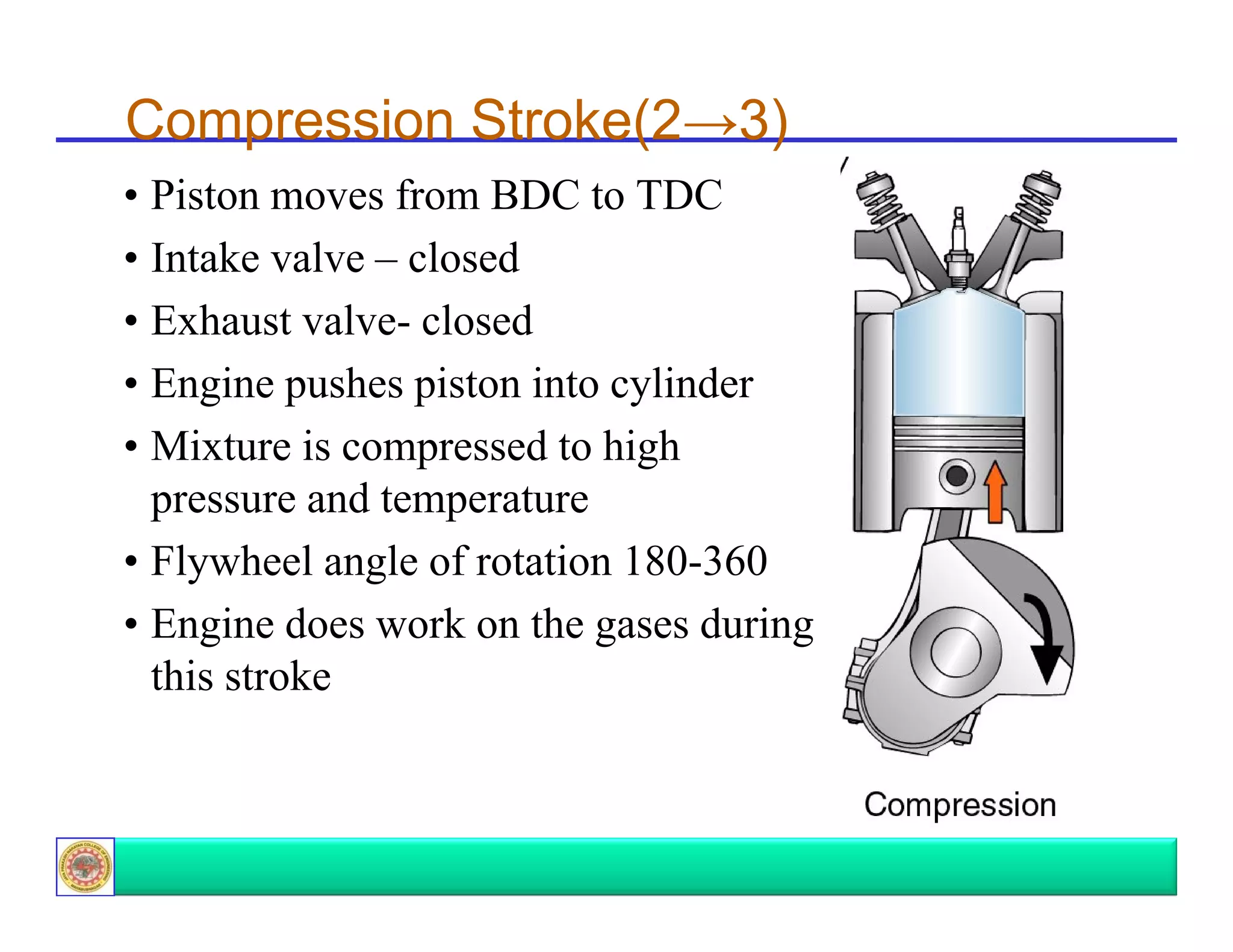
Explains the compression stroke in a four-stroke cycle, focusing on pressure and temperature changes.
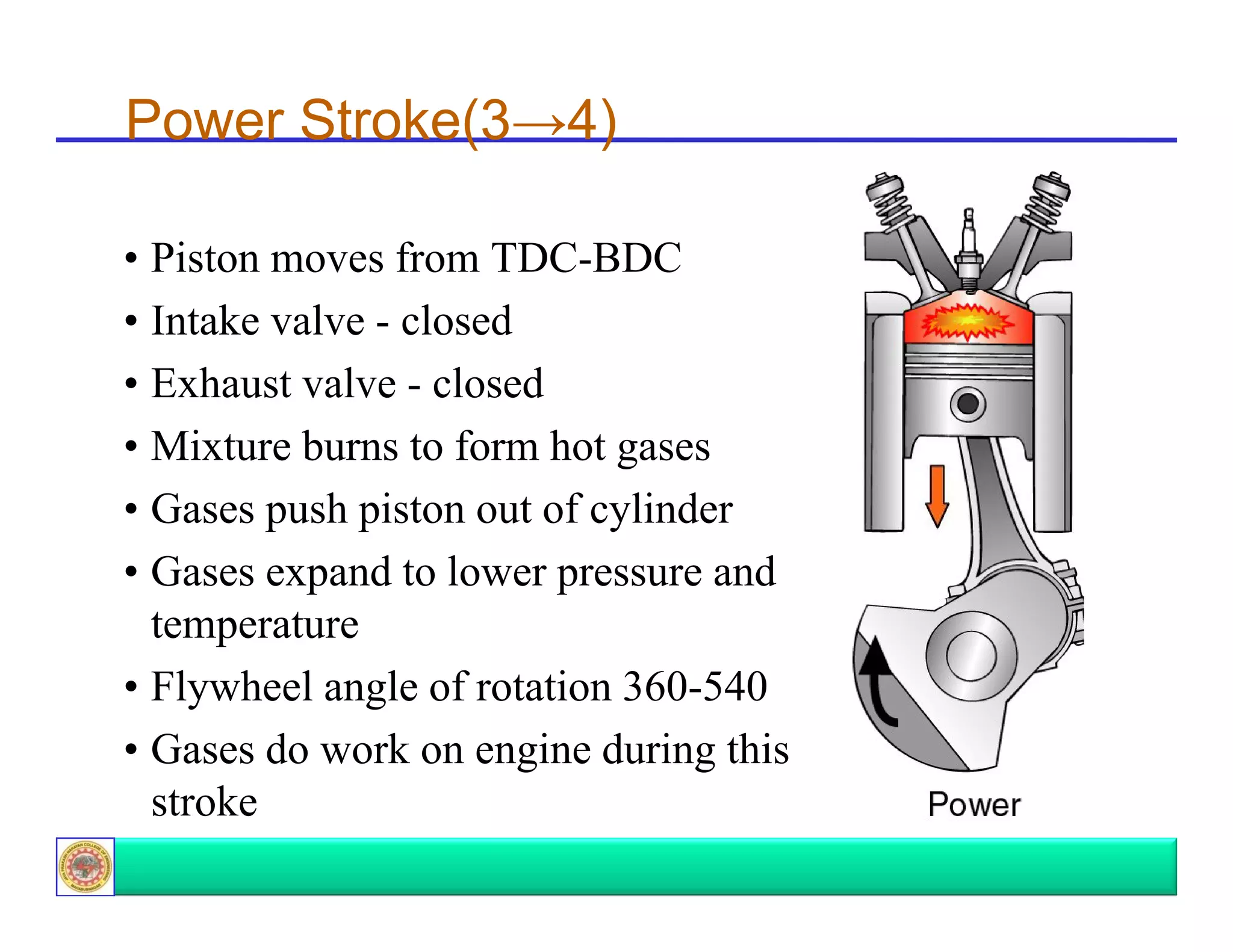
Describes the power stroke in detail, including combustion and the resultant force on the piston.
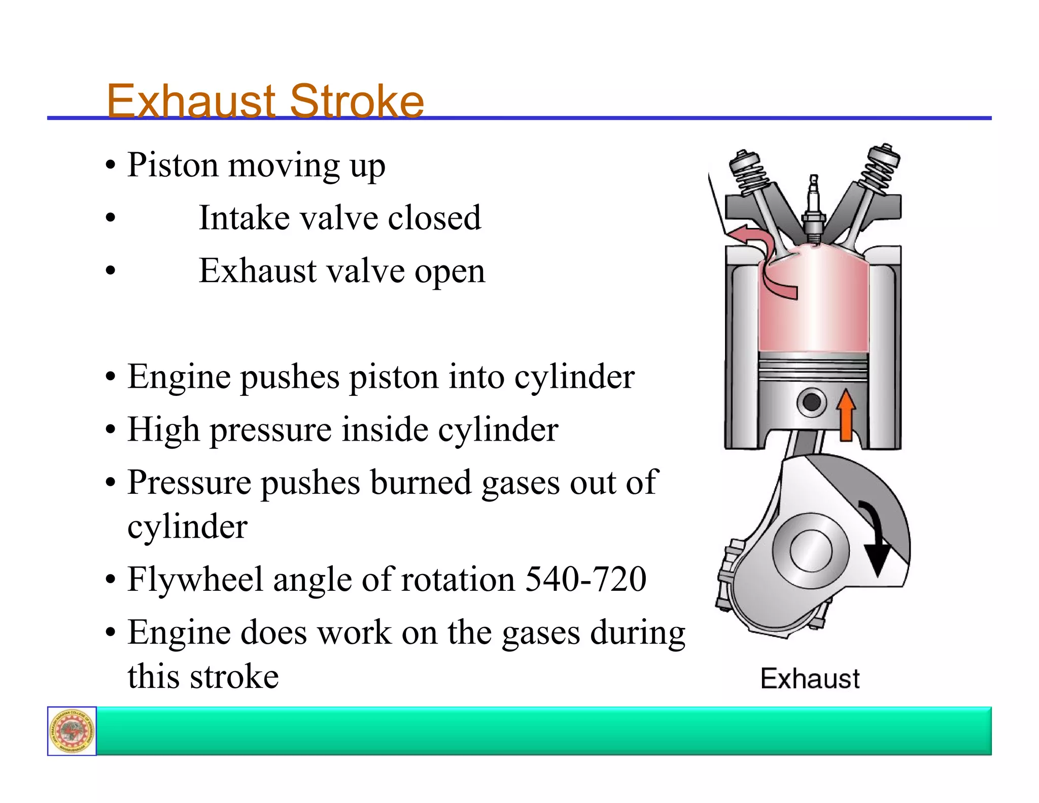
Details the exhaust stroke process, emphasizing the expulsion of burnt gases from the cylinder.
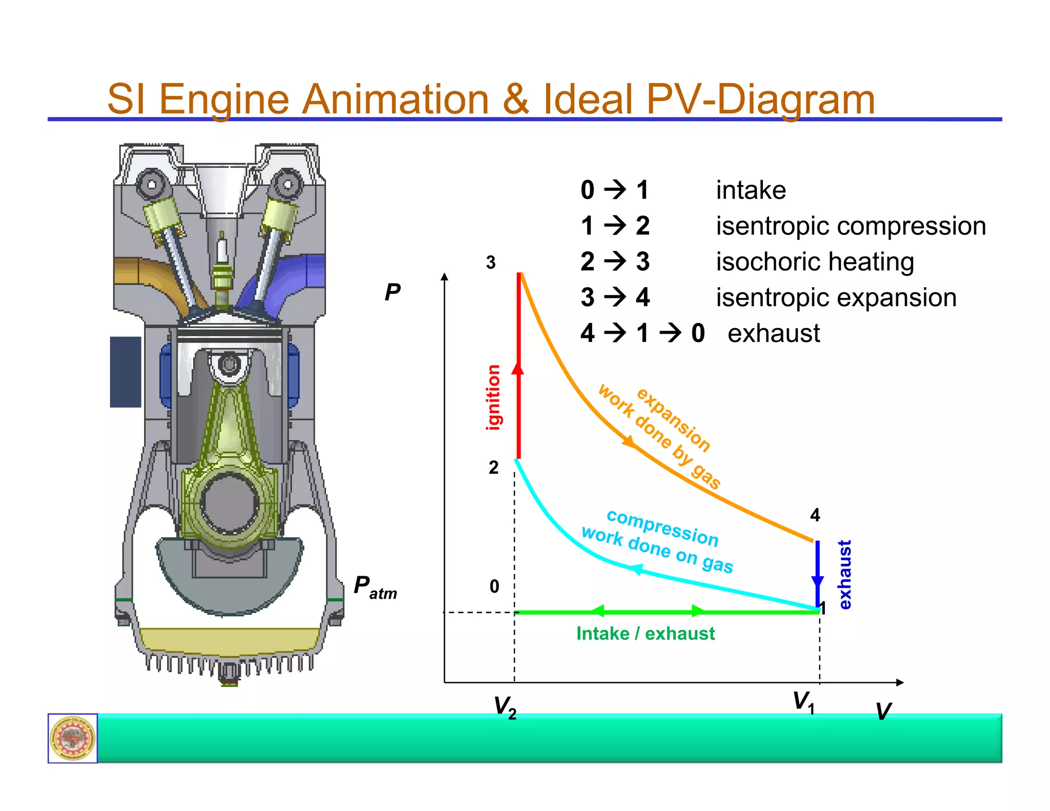
Illustrates pressure-volume (PV) diagrams for a four-stroke engine cycle, covering all essential phases.
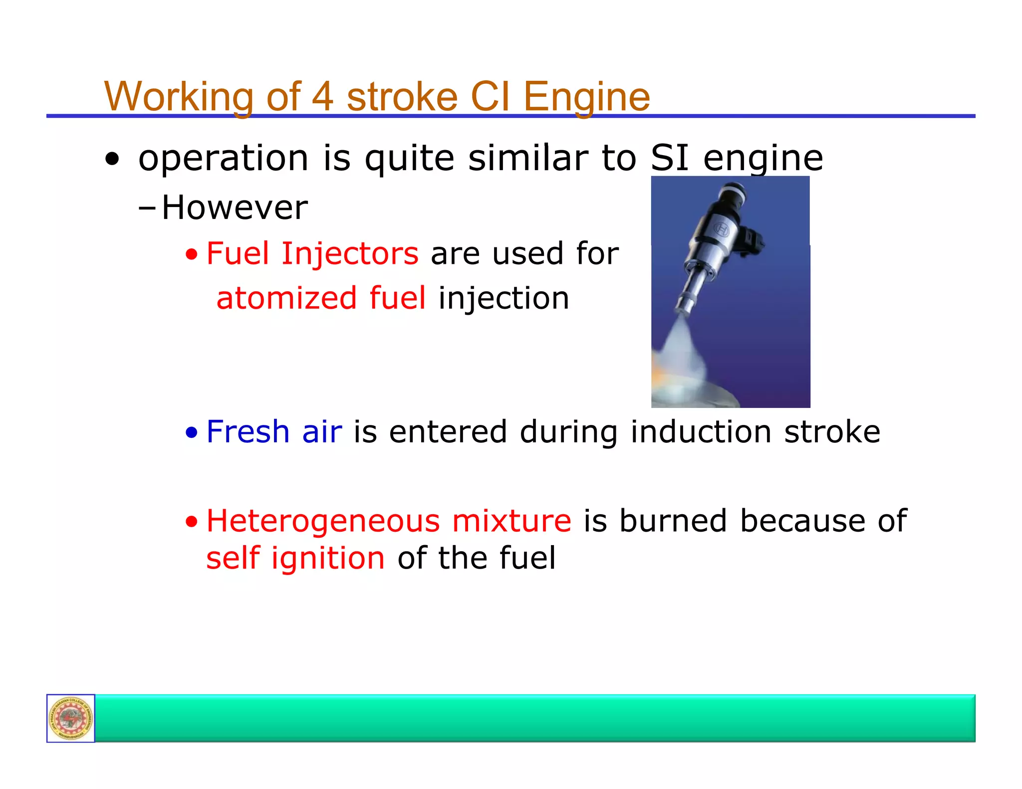
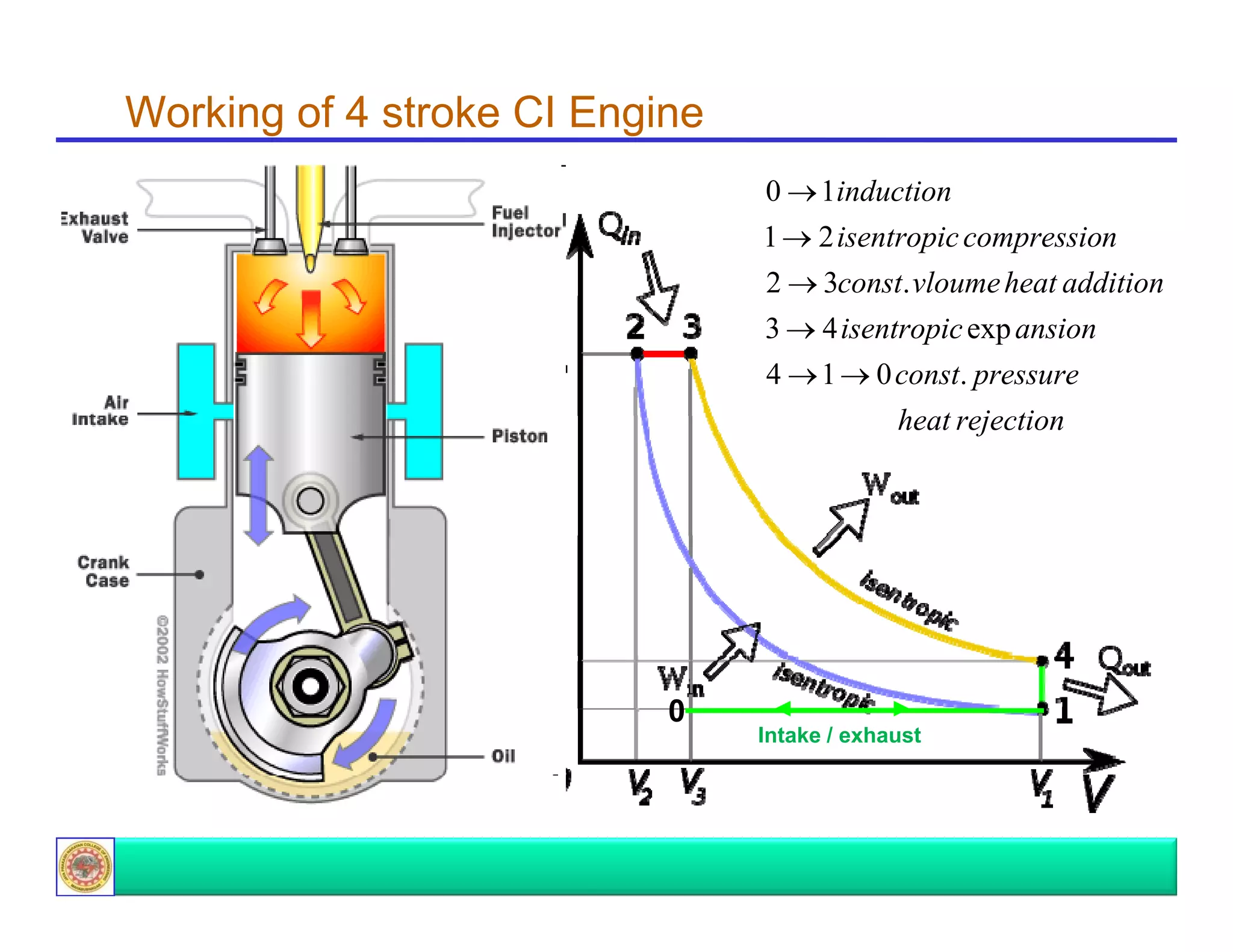
Explains the operation of the four-stroke compression ignition engine, highlighting fuel injection and air mixing.
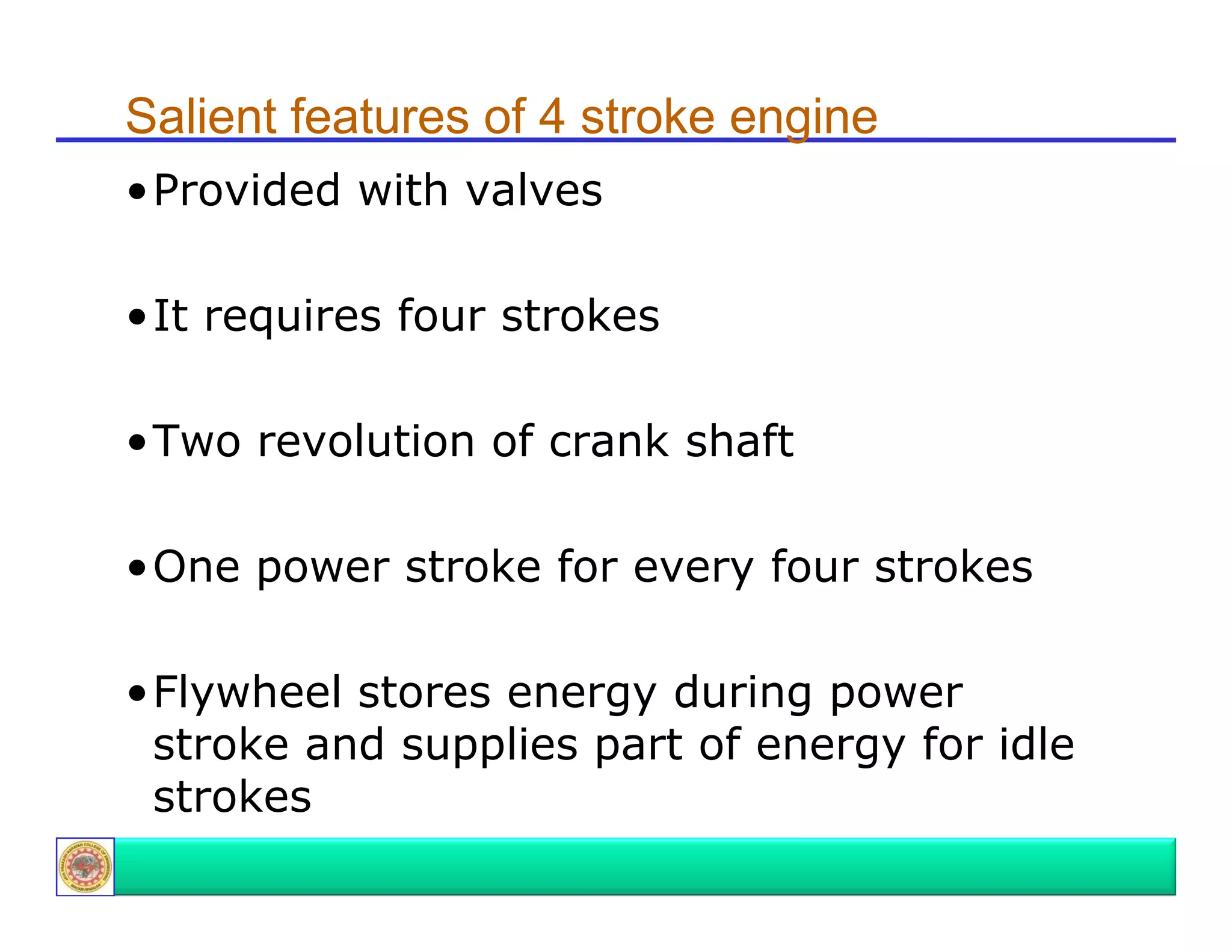
Highlights the key features of a four-stroke engine, including its operational mechanics and power stroke generation.
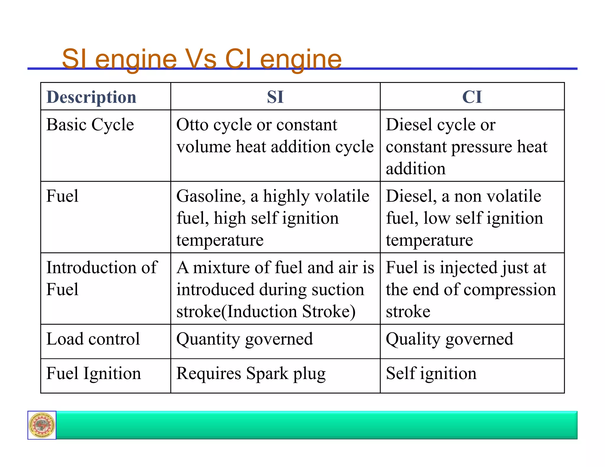
Contrasts the basic cycles, fuel types, and load control mechanisms utilized in SI (Spark Ignition) and CI (Compression Ignition) engines.
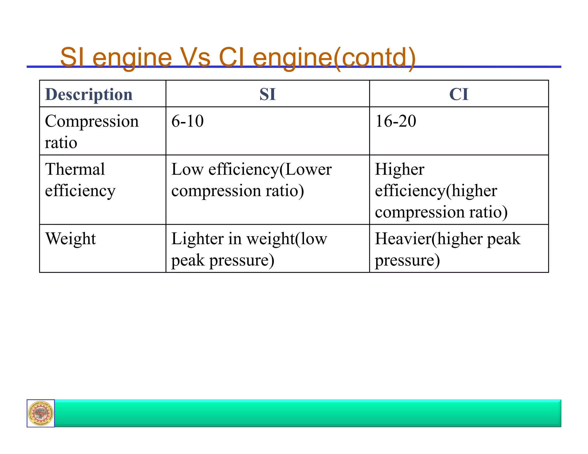
Further comparison of SI and CI engines focusing on thermal efficiency, compression ratios, and weight differences.
Conclusion of the presentation with gratitude and contact information for further queries.


![SBP- IC Engines [Compatibility Mode] (1).pdf](https://cdn.slidesharecdn.com/ss_thumbnails/sbp-icenginescompatibilitymode1-241227102120-3fc3e41a-thumbnail.jpg?width=640&height=640&fit=bounds)


