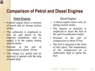
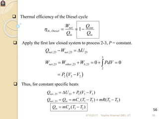
1. The document discusses internal combustion engines, which convert chemical energy from fuels like gasoline and natural gas into mechanical work.
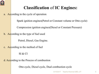
2. Internal combustion engines are commonly used in automobiles, boats, airplanes, power generators, and other machinery. They can be classified based on their fuel, ignition method, combustion cycle, and other factors.
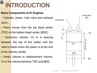
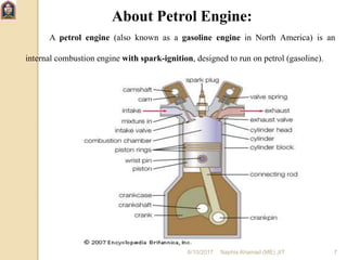
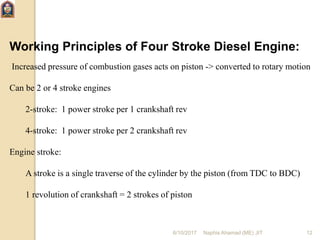
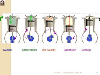
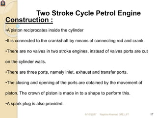
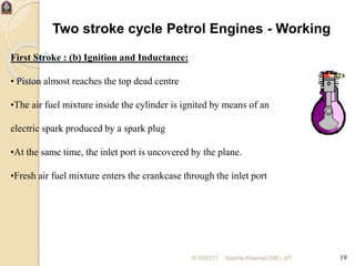
3. The document then focuses on describing the basic components and operating cycles of 4-stroke gasoline/petrol and diesel engines, as well as 2-stroke petrol engines. It provides details on the intake, compression, power, and exhaust strokes in each engine type.