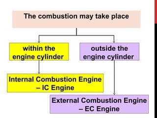
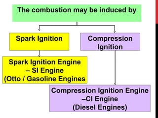
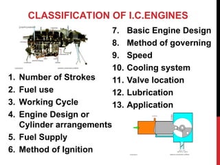
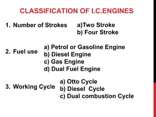
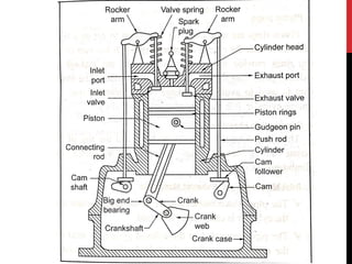
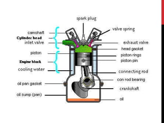
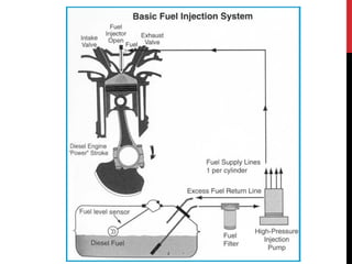
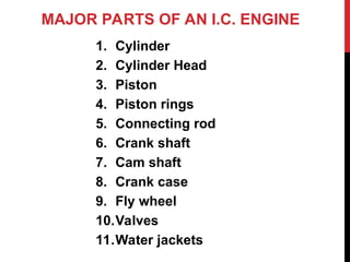
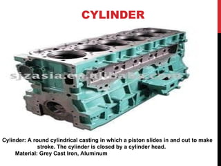
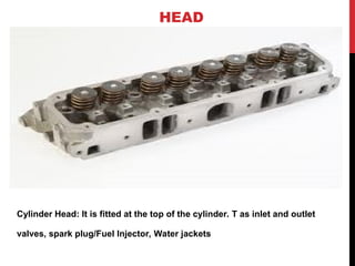
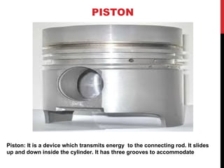
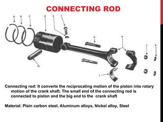
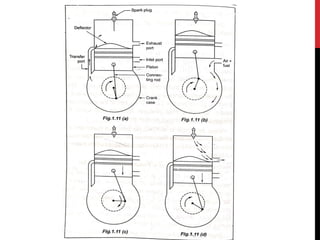
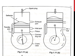
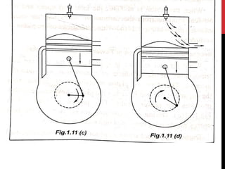
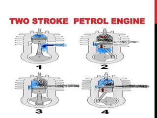
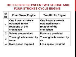
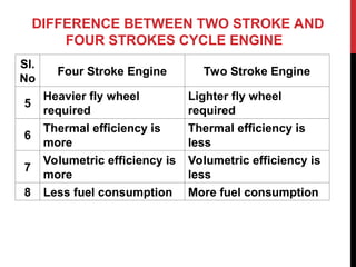
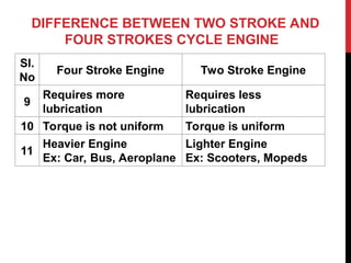
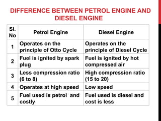
20ME703PE &
ADVANCED IC ENGINES
INTERNAL COMBUSTION ENGINES
(IC ENGINES)`
INTRODUCTION
Perhaps the invention of the engine, or even introducing its
concept, was the most important scientific event in the
human history.
The revolutionary result was the replacement of the horse
carriage by the automobile or the HORSE-LESS CARRIAGE,
as it was initially called.
Engines are basic mechanical engineering devices, and they
have variety of applications in moving and non-moving
machines
NIKOLAS OTTO (1876)
History of I.C. Engine The internal combustion engine was first conceived and
developed in the late 1800’s•The man who is considered the inventor of the
modern IC engine and the founder of the industry is pictured to the TOP….Nikolas
Otto (1832-1891).•Otto developed a four-stroke engine in 1876, most often
referred to as a Spark Ignition, since a spark is needed to ignite the fuel air
mixture.
WHAT IS AN ENGINE’?
Engine is a device that converts heat
energy into mechanical energy
Heat energy is obtained
by
combustion of fuel
The combustion may take place
within the
engine cylinder
outside the
engine cylinder
Internal Combustion Engine
– IC Engine
External Combustion Engine
– EC Engine
Spark Ignition Compression
Ignition
Spark Ignition Engine
– SI Engine
(Otto / Gasoline Engines
Compression Ignition Engine
–CI Engine
(Diesel Engines)
The combustion may be induced by
CLASSIFICATION OF I.C.ENGINES
1. Number of Strokes
2. Fuel use
3. Working Cycle
4. Engine Design or
Cylinder arrangements
5. Fuel Supply
6. Method of Ignition
7. Basic Engine Design
8. Method of governing
9. Speed
10. Cooling system
11. Valve location
12. Lubrication
13. Application
CLASSIFICATION OF I.C.ENGINES
1. Number of Strokes
2. Fuel use
3. Working Cycle
a)Two Stroke
b) Four Stroke
a) Petrol or Gasoline Engine
b) Diesel Engine
c) Gas Engine
d) Dual Fuel Engine
a) Otto Cycle
b) Diesel Cycle
c) Dual combustion Cycle
CLASSIFICATION OF I.C.ENGINES
4. Engine Design or Cylinder arrangements
5. Fuel Supply
6. Method of Ignition
a) Inline Engine
b) V Engine
c) Radial Engine
d) Opposed Cylinder Engine
e) Vertical engine
f) Horizontal Engine
a) Carbureted Type
b) Injection Type
a) Spark Ignition
b) Compression Ignition
CLASSIFICATION OF I.C.ENGINES
7. Basic Engine Design
8. Method of governing
9. Speed
a) Quality Governed Engine
b) Rotary Engine
a) Quality Governed Engine
b) Quantity Governed Engine
c) Hit & Miss Governed Engine
a) Low Speed Engine
b) High Speed Engine
c) Medium Speed Engine
CLASSIFICATION OF I.C.ENGINES
10. Cooling system
11. Valve location
12. Lubrication
a) Air Cooled Engine
b) Water Cooled Engine
a) Overhead Valve Engine
b) Side valve Engine
a) Wet sump lubrication Engine
b) Dry Sump Lubrication Engine
CLASSIFICATION OF I.C.ENGINES
13. Application
a) Stationary Engine – Pump sets, Gensets,
Mills etc.,
b) Marine Engine – Ship. Outboard, Inboard etc.,
c) Locomotive Engine – Earth movers, Snow
Movers, Tractors, Tippers, Dumpers etc.,
d) Automotive Engine – Car, Bus, Trucks etc.,
e) Aircraft Engine – Civil Aircrafts, War air Crafts
etc.,
MAJOR PARTS OF AN I.C. ENGINE
1. Cylinder
2. Cylinder Head
3. Piston
4. Piston rings
5. Connecting rod
6. Crank shaft
7. Cam shaft
8. Crank case
9. Fly wheel
10.Valves
11.Water jackets
CYLINDER
Cylinder: A round cylindrical casting in which a piston slides in and out to make
stroke. The cylinder is closed by a cylinder head.
Material: Grey Cast Iron, Aluminum
HEAD
Cylinder Head: It is fitted at the top of the cylinder. T as inlet and outlet
valves, spark plug/Fuel Injector, Water jackets
PISTON
Piston: It is a device which transmits energy to the connecting rod. It slides
up and down inside the cylinder. It has three grooves to accommodate
PISTON RINGS
Piston rings: Piston rings are inserted in the grooves of piston.
1). Oil ring: One ring is used
2). Compression Rings: Two rings are used
Material: Alloy cast iron plated with chromium or cadmium
CONNECTING ROD
Connecting rod: It converts the reciprocating motion of the piston into rotary
motion of the crank shaft. The small end of the connecting rod is
connected to piston and the big end to the crank shaft
Material: Plain carbon steel, Aluminum alloys, Nickel alloy, Steel
CRANK SHAFT
Crank shaft: The device used for getting power from the motion of the
piston and connecting rod and this power is applied to the flywheel
Material: Alloy steel, SG Iron
FLY WHEEL
9. Fly wheel: It is a big wheel attached with crank shaft. It maintains the
speed of the engine.
CAM SHAFT
7. Cam shaft: It operates the opening and closing of the engine valves. It
has number of cams which are driven by crank shaft through timing
gears. The function of the cam is to convert the rotary motion into linear
reciprocating motion
VALVES
Valves: The function of the valve is to admit fresh charge in the cylinder and to
send the discharge gases out. There are two valves namely inlet valve and
outlet valve.
Material
Inlet Valve: Nickel Chrome, Chrome molybdenum
Outlet Valve: Nickel Chrome, Stainless Steel, Tungsten Steel, Silicon chrome
steel
WATER JACKETS
1. Water jackets: Provided in the cylinder head. Purpose of the water
jackets is to keep the walls of the engine cool.
FOUR STROKE ENGINE
In a four stroke engine, one power stroke is
completed for every four strokes of the piston
or during two revolutions of the crankshaft
Petrol Engine: It is also known as Spark
Ignition (SI) Engine.
Four stroke Petrol requires four strokes of the
piston for one cycle of operation
The four strokes are:
1. Suction stroke 2. Compression stroke
3. Expansion stroke 4. Exhaust stroke
4 STROKES OF THE IC ENGINE
TWO STROKE ENGINE
In the two stroke engine, the cycle of operation
is completed in two strokes of the piston or one
revolution of the crankshaft .
The charging of the cylinder with air-fuel
mixture (or air) is done by the following two
methods.
TWO STROKE ENGINE
1.Closed Crank compression: The piston
movement is caused by air in the crank case.
So the compressed air admitted into the
cylinder
2.Separate pump method: The charged air or
the air-fuel mixture is compressed by a
separate pump and the pump is driven by the
engine itself.
This method is used in multi cylinder engines
TWO STROKE PETROL ENGINE
WORKING PRINCIPLE OF TWO STROKE
PETROL ENGINE
In two stroke engine, one power stroke is
completed for every two strokes of the
piston or one revolution of the crankshaft
A two stroke engine has no valves and only
ports are present. There are three ports
namely inlet port, exhaust port and transfer
ports.
WORKING PRINCIPLE OF TWO STROKE
PETROL ENGINE
The strokes are:
1.First stroke – compression, suction and
ignition
2.Second stroke – Expansion and exhaustion
DIESEL ENGINE
OR
COMPRESSION IGNITION ENGINE
(C.I. ENGINE)
WORKING PRINCIPLE OF DIESEL
ENGINE
The working is similar to that of a petrol
engine and the only difference is a fuel injector
is present instead of a spark plug.
This is known as “Diesel Cycle”
WORKING PRINCIPLE OF FOUR STROKE
DIESEL ENGINE
1.Suction Stroke
2.Compression Stroke
3.Power or Working Stroke of Expansion stroke
4.Exhaust Stroke
FOUR STROKE DIESEL
ENGINE
WORKING PRINCIPLE OF TWO STROKE
DIESEL ENGINE
1.First Stroke - Compression and Ignition
(Upward movement of Piston)
2.Second Stroke – Expansion and Exhaust
(Down Ward movement of Piston)
TWO STROKE DIESEL ENGINE
DIFFERENCE BETWEEN TWO STROKE AND
FOUR STROKES CYCLE ENGINE
Sl.
No
Four Stroke Engine Two Stroke Engine
1
One Power stroke is
obtained in two
rotations of the
crankshaft
One Power stroke is
obtained in each
rotation of the
crankshaft
2 Valves are provided Ports are provided
3
The engine is cooled by
water
The engine is cooled by
air
4 More space required Less space required
DIFFERENCE BETWEEN TWO STROKE AND
FOUR STROKES CYCLE ENGINE
Sl.
No
Four Stroke Engine Two Stroke Engine
5
Heavier fly wheel
required
Lighter fly wheel
required
6
Thermal efficiency is
more
Thermal efficiency is
less
7
Volumetric efficiency is
more
Volumetric efficiency is
less
8 Less fuel consumption More fuel consumption
DIFFERENCE BETWEEN TWO STROKE AND
FOUR STROKES CYCLE ENGINE
Sl.
No
Four Stroke Engine Two Stroke Engine
9
Requires more
lubrication
Requires less
lubrication
10 Torque is not uniform Torque is uniform
11
Heavier Engine
Ex: Car, Bus, Aeroplane
Lighter Engine
Ex: Scooters, Mopeds
DIFFERENCE BETWEEN PETROL ENGINE AND
DIESEL ENGINE
Sl.
No
Petrol Engine Diesel Engine
1
Operates on the
principle of Otto Cycle
Operates on the
principle of Diesel Cycle
2
Fuel is ignited by spark
plug
Fuel is ignited by hot
compressed air
3
Less compression ratio
(6 to 8)
High compression ratio
(15 to 20)
4 Operates at high speed Low speed
5
Fuel used is petrol and
costly
Fuel used is diesel and
cost is less
DIFFERENCE BETWEEN PETROL ENGINE AND
DIESEL ENGINE
Sl.
No
Petrol Engine Diesel Engine
6 Lighter in weight Heavier in weight
7
Fuel is sent to cylinder
through carburetor
Fuel is sent through
fuel injector
8
Fuel consumption is
more
Fuel consumption is
less
9 Less Vibration More Vibration
10
Petrol is more volatile.
So, handling is more
risky
Diesel is less volatile.
So, handling is not risky
Thank You

Internal Combustion Engine Introduction

  • 1.
  • 2.
  • 3.
    INTRODUCTION Perhaps the inventionof the engine, or even introducing its concept, was the most important scientific event in the human history. The revolutionary result was the replacement of the horse carriage by the automobile or the HORSE-LESS CARRIAGE, as it was initially called. Engines are basic mechanical engineering devices, and they have variety of applications in moving and non-moving machines
  • 4.
    NIKOLAS OTTO (1876) Historyof I.C. Engine The internal combustion engine was first conceived and developed in the late 1800’s•The man who is considered the inventor of the modern IC engine and the founder of the industry is pictured to the TOP….Nikolas Otto (1832-1891).•Otto developed a four-stroke engine in 1876, most often referred to as a Spark Ignition, since a spark is needed to ignite the fuel air mixture.
  • 5.
    WHAT IS ANENGINE’? Engine is a device that converts heat energy into mechanical energy Heat energy is obtained by combustion of fuel
  • 6.
    The combustion maytake place within the engine cylinder outside the engine cylinder Internal Combustion Engine – IC Engine External Combustion Engine – EC Engine
  • 7.
    Spark Ignition Compression Ignition SparkIgnition Engine – SI Engine (Otto / Gasoline Engines Compression Ignition Engine –CI Engine (Diesel Engines) The combustion may be induced by
  • 8.
    CLASSIFICATION OF I.C.ENGINES 1.Number of Strokes 2. Fuel use 3. Working Cycle 4. Engine Design or Cylinder arrangements 5. Fuel Supply 6. Method of Ignition 7. Basic Engine Design 8. Method of governing 9. Speed 10. Cooling system 11. Valve location 12. Lubrication 13. Application
  • 9.
    CLASSIFICATION OF I.C.ENGINES 1.Number of Strokes 2. Fuel use 3. Working Cycle a)Two Stroke b) Four Stroke a) Petrol or Gasoline Engine b) Diesel Engine c) Gas Engine d) Dual Fuel Engine a) Otto Cycle b) Diesel Cycle c) Dual combustion Cycle
  • 10.
    CLASSIFICATION OF I.C.ENGINES 4.Engine Design or Cylinder arrangements 5. Fuel Supply 6. Method of Ignition a) Inline Engine b) V Engine c) Radial Engine d) Opposed Cylinder Engine e) Vertical engine f) Horizontal Engine a) Carbureted Type b) Injection Type a) Spark Ignition b) Compression Ignition
  • 11.
    CLASSIFICATION OF I.C.ENGINES 7.Basic Engine Design 8. Method of governing 9. Speed a) Quality Governed Engine b) Rotary Engine a) Quality Governed Engine b) Quantity Governed Engine c) Hit & Miss Governed Engine a) Low Speed Engine b) High Speed Engine c) Medium Speed Engine
  • 12.
    CLASSIFICATION OF I.C.ENGINES 10.Cooling system 11. Valve location 12. Lubrication a) Air Cooled Engine b) Water Cooled Engine a) Overhead Valve Engine b) Side valve Engine a) Wet sump lubrication Engine b) Dry Sump Lubrication Engine
  • 13.
    CLASSIFICATION OF I.C.ENGINES 13.Application a) Stationary Engine – Pump sets, Gensets, Mills etc., b) Marine Engine – Ship. Outboard, Inboard etc., c) Locomotive Engine – Earth movers, Snow Movers, Tractors, Tippers, Dumpers etc., d) Automotive Engine – Car, Bus, Trucks etc., e) Aircraft Engine – Civil Aircrafts, War air Crafts etc.,
  • 17.
    MAJOR PARTS OFAN I.C. ENGINE 1. Cylinder 2. Cylinder Head 3. Piston 4. Piston rings 5. Connecting rod 6. Crank shaft 7. Cam shaft 8. Crank case 9. Fly wheel 10.Valves 11.Water jackets
  • 18.
    CYLINDER Cylinder: A roundcylindrical casting in which a piston slides in and out to make stroke. The cylinder is closed by a cylinder head. Material: Grey Cast Iron, Aluminum
  • 19.
    HEAD Cylinder Head: Itis fitted at the top of the cylinder. T as inlet and outlet valves, spark plug/Fuel Injector, Water jackets
  • 20.
    PISTON Piston: It isa device which transmits energy to the connecting rod. It slides up and down inside the cylinder. It has three grooves to accommodate
  • 21.
    PISTON RINGS Piston rings:Piston rings are inserted in the grooves of piston. 1). Oil ring: One ring is used 2). Compression Rings: Two rings are used Material: Alloy cast iron plated with chromium or cadmium
  • 22.
    CONNECTING ROD Connecting rod:It converts the reciprocating motion of the piston into rotary motion of the crank shaft. The small end of the connecting rod is connected to piston and the big end to the crank shaft Material: Plain carbon steel, Aluminum alloys, Nickel alloy, Steel
  • 23.
    CRANK SHAFT Crank shaft:The device used for getting power from the motion of the piston and connecting rod and this power is applied to the flywheel Material: Alloy steel, SG Iron
  • 24.
    FLY WHEEL 9. Flywheel: It is a big wheel attached with crank shaft. It maintains the speed of the engine.
  • 25.
    CAM SHAFT 7. Camshaft: It operates the opening and closing of the engine valves. It has number of cams which are driven by crank shaft through timing gears. The function of the cam is to convert the rotary motion into linear reciprocating motion
  • 26.
    VALVES Valves: The functionof the valve is to admit fresh charge in the cylinder and to send the discharge gases out. There are two valves namely inlet valve and outlet valve. Material Inlet Valve: Nickel Chrome, Chrome molybdenum Outlet Valve: Nickel Chrome, Stainless Steel, Tungsten Steel, Silicon chrome steel
  • 27.
    WATER JACKETS 1. Waterjackets: Provided in the cylinder head. Purpose of the water jackets is to keep the walls of the engine cool.
  • 28.
    FOUR STROKE ENGINE Ina four stroke engine, one power stroke is completed for every four strokes of the piston or during two revolutions of the crankshaft Petrol Engine: It is also known as Spark Ignition (SI) Engine. Four stroke Petrol requires four strokes of the piston for one cycle of operation The four strokes are: 1. Suction stroke 2. Compression stroke 3. Expansion stroke 4. Exhaust stroke
  • 30.
    4 STROKES OFTHE IC ENGINE
  • 31.
    TWO STROKE ENGINE Inthe two stroke engine, the cycle of operation is completed in two strokes of the piston or one revolution of the crankshaft . The charging of the cylinder with air-fuel mixture (or air) is done by the following two methods.
  • 32.
    TWO STROKE ENGINE 1.ClosedCrank compression: The piston movement is caused by air in the crank case. So the compressed air admitted into the cylinder 2.Separate pump method: The charged air or the air-fuel mixture is compressed by a separate pump and the pump is driven by the engine itself. This method is used in multi cylinder engines
  • 36.
  • 37.
    WORKING PRINCIPLE OFTWO STROKE PETROL ENGINE In two stroke engine, one power stroke is completed for every two strokes of the piston or one revolution of the crankshaft A two stroke engine has no valves and only ports are present. There are three ports namely inlet port, exhaust port and transfer ports.
  • 38.
    WORKING PRINCIPLE OFTWO STROKE PETROL ENGINE The strokes are: 1.First stroke – compression, suction and ignition 2.Second stroke – Expansion and exhaustion
  • 39.
  • 40.
    WORKING PRINCIPLE OFDIESEL ENGINE The working is similar to that of a petrol engine and the only difference is a fuel injector is present instead of a spark plug. This is known as “Diesel Cycle”
  • 41.
    WORKING PRINCIPLE OFFOUR STROKE DIESEL ENGINE 1.Suction Stroke 2.Compression Stroke 3.Power or Working Stroke of Expansion stroke 4.Exhaust Stroke
  • 42.
  • 43.
    WORKING PRINCIPLE OFTWO STROKE DIESEL ENGINE 1.First Stroke - Compression and Ignition (Upward movement of Piston) 2.Second Stroke – Expansion and Exhaust (Down Ward movement of Piston)
  • 44.
  • 45.
    DIFFERENCE BETWEEN TWOSTROKE AND FOUR STROKES CYCLE ENGINE Sl. No Four Stroke Engine Two Stroke Engine 1 One Power stroke is obtained in two rotations of the crankshaft One Power stroke is obtained in each rotation of the crankshaft 2 Valves are provided Ports are provided 3 The engine is cooled by water The engine is cooled by air 4 More space required Less space required
  • 46.
    DIFFERENCE BETWEEN TWOSTROKE AND FOUR STROKES CYCLE ENGINE Sl. No Four Stroke Engine Two Stroke Engine 5 Heavier fly wheel required Lighter fly wheel required 6 Thermal efficiency is more Thermal efficiency is less 7 Volumetric efficiency is more Volumetric efficiency is less 8 Less fuel consumption More fuel consumption
  • 47.
    DIFFERENCE BETWEEN TWOSTROKE AND FOUR STROKES CYCLE ENGINE Sl. No Four Stroke Engine Two Stroke Engine 9 Requires more lubrication Requires less lubrication 10 Torque is not uniform Torque is uniform 11 Heavier Engine Ex: Car, Bus, Aeroplane Lighter Engine Ex: Scooters, Mopeds
  • 48.
    DIFFERENCE BETWEEN PETROLENGINE AND DIESEL ENGINE Sl. No Petrol Engine Diesel Engine 1 Operates on the principle of Otto Cycle Operates on the principle of Diesel Cycle 2 Fuel is ignited by spark plug Fuel is ignited by hot compressed air 3 Less compression ratio (6 to 8) High compression ratio (15 to 20) 4 Operates at high speed Low speed 5 Fuel used is petrol and costly Fuel used is diesel and cost is less
  • 49.
    DIFFERENCE BETWEEN PETROLENGINE AND DIESEL ENGINE Sl. No Petrol Engine Diesel Engine 6 Lighter in weight Heavier in weight 7 Fuel is sent to cylinder through carburetor Fuel is sent through fuel injector 8 Fuel consumption is more Fuel consumption is less 9 Less Vibration More Vibration 10 Petrol is more volatile. So, handling is more risky Diesel is less volatile. So, handling is not risky
  • 50.