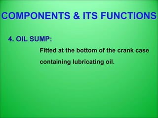
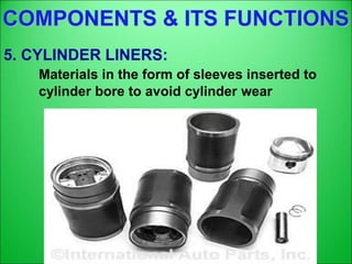
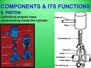
Download to read offline

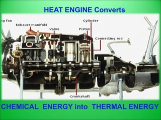
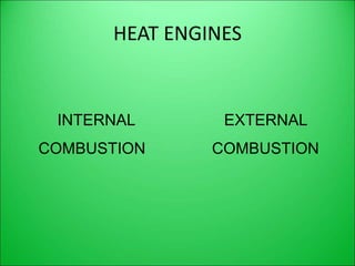
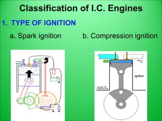
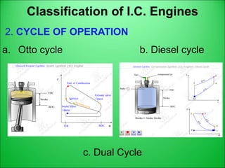
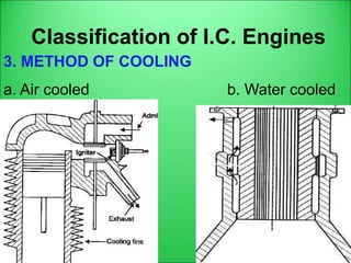
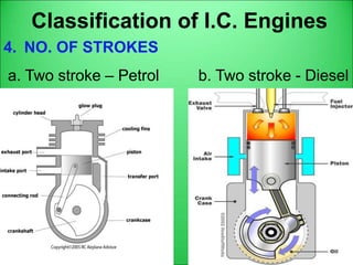
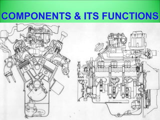
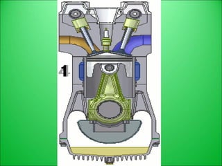
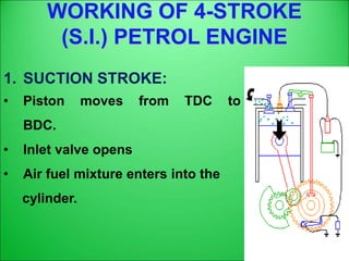
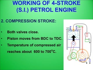
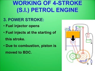
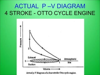
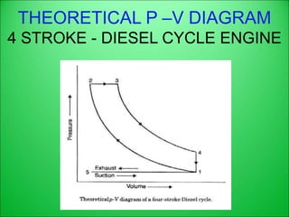
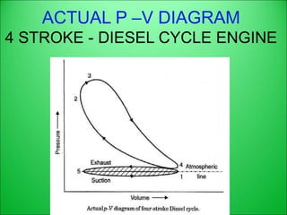
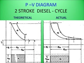
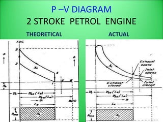
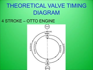
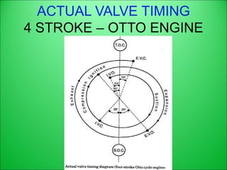
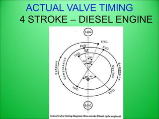
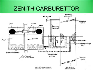
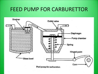
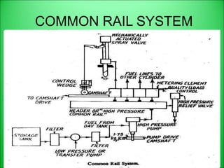
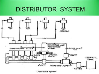
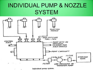
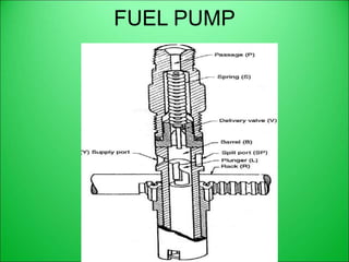
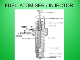
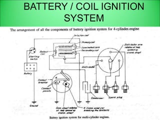
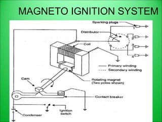
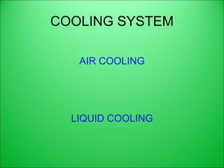
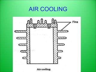


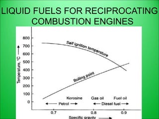

The document provides a comprehensive overview of internal combustion engines, discussing their classifications based on ignition type, cycle of operation, cooling method, and various components such as the cylinder block, piston, and fuel injection systems. It also details the working mechanisms of four-stroke and two-stroke engines, comparing their performance and applications. Additionally, it covers lubrication systems, governing methods, and properties of liquid fuels used in these engines.


