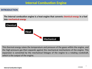
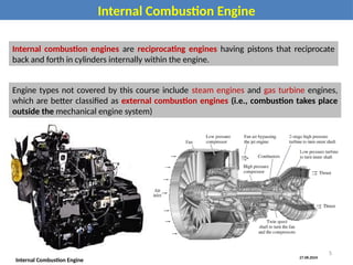
The document provides a comprehensive overview of internal combustion engines, including their historical development, types, operating characteristics, and emission impacts. It covers various engine cycles, design classifications, component functions, and the thermochemical processes involved in converting fuel into mechanical energy. Emissions from these engines, such as hydrocarbons and nitrogen oxides, are highlighted as significant contributors to air pollution.


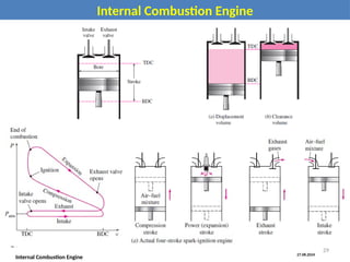


![SBP- IC Engines [Compatibility Mode] (1).pdf](https://cdn.slidesharecdn.com/ss_thumbnails/sbp-icenginescompatibilitymode1-241227102120-3fc3e41a-thumbnail.jpg?width=640&height=640&fit=bounds)


