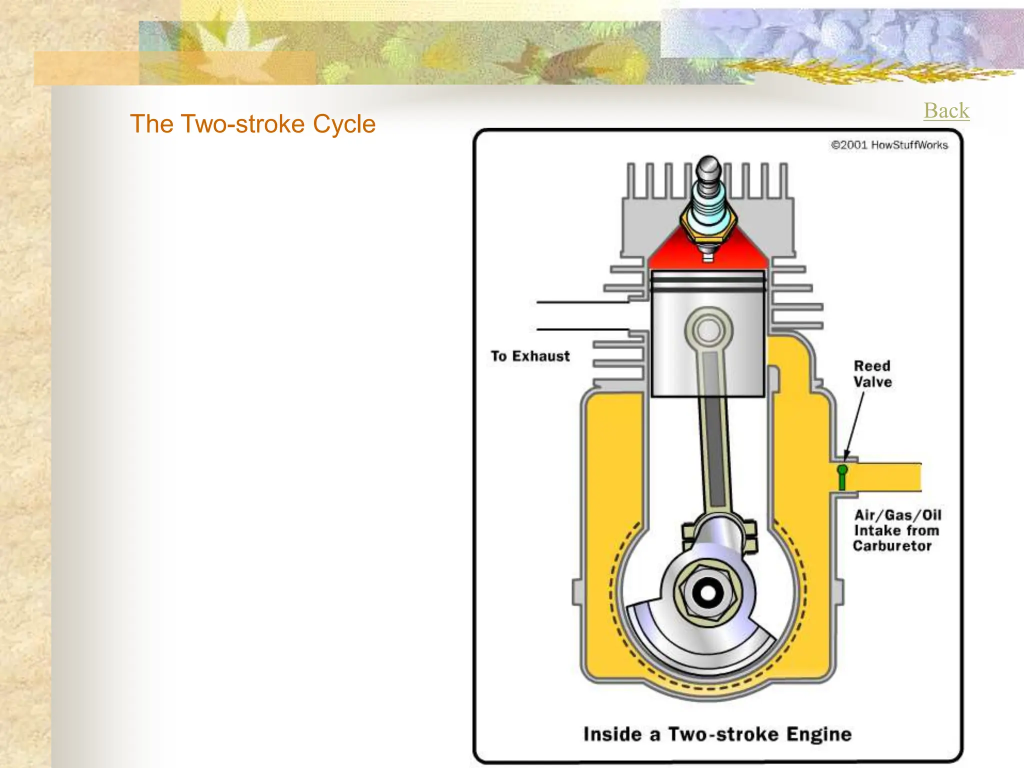
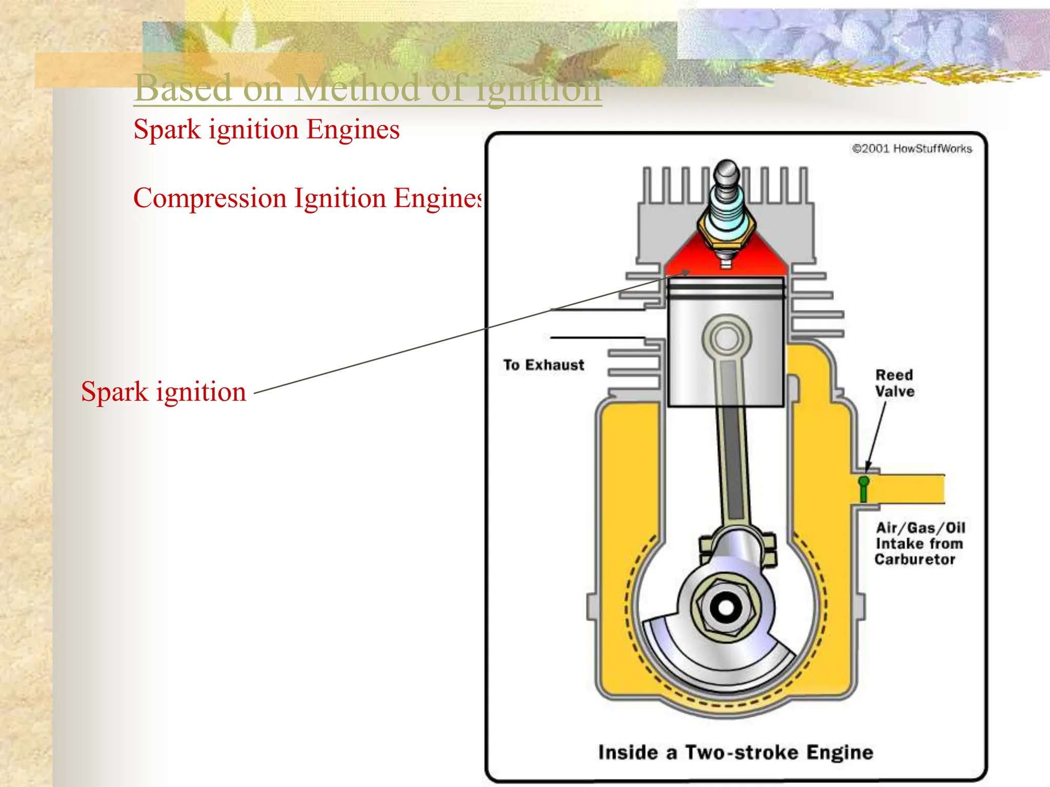
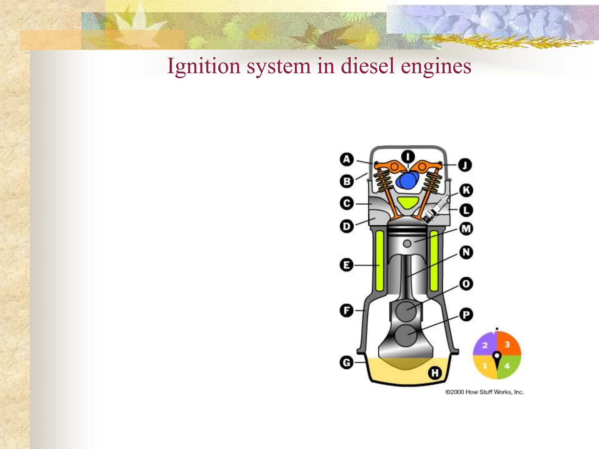
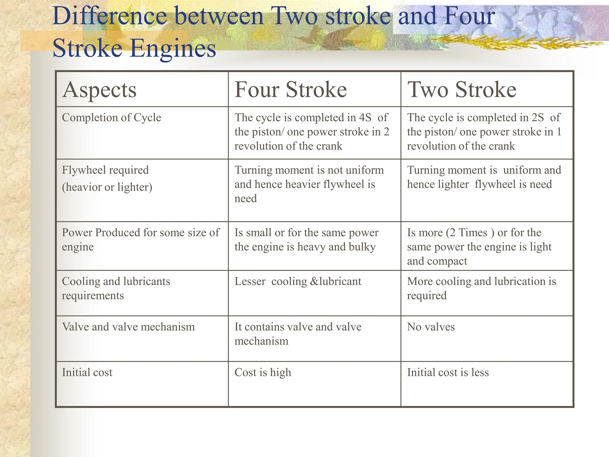
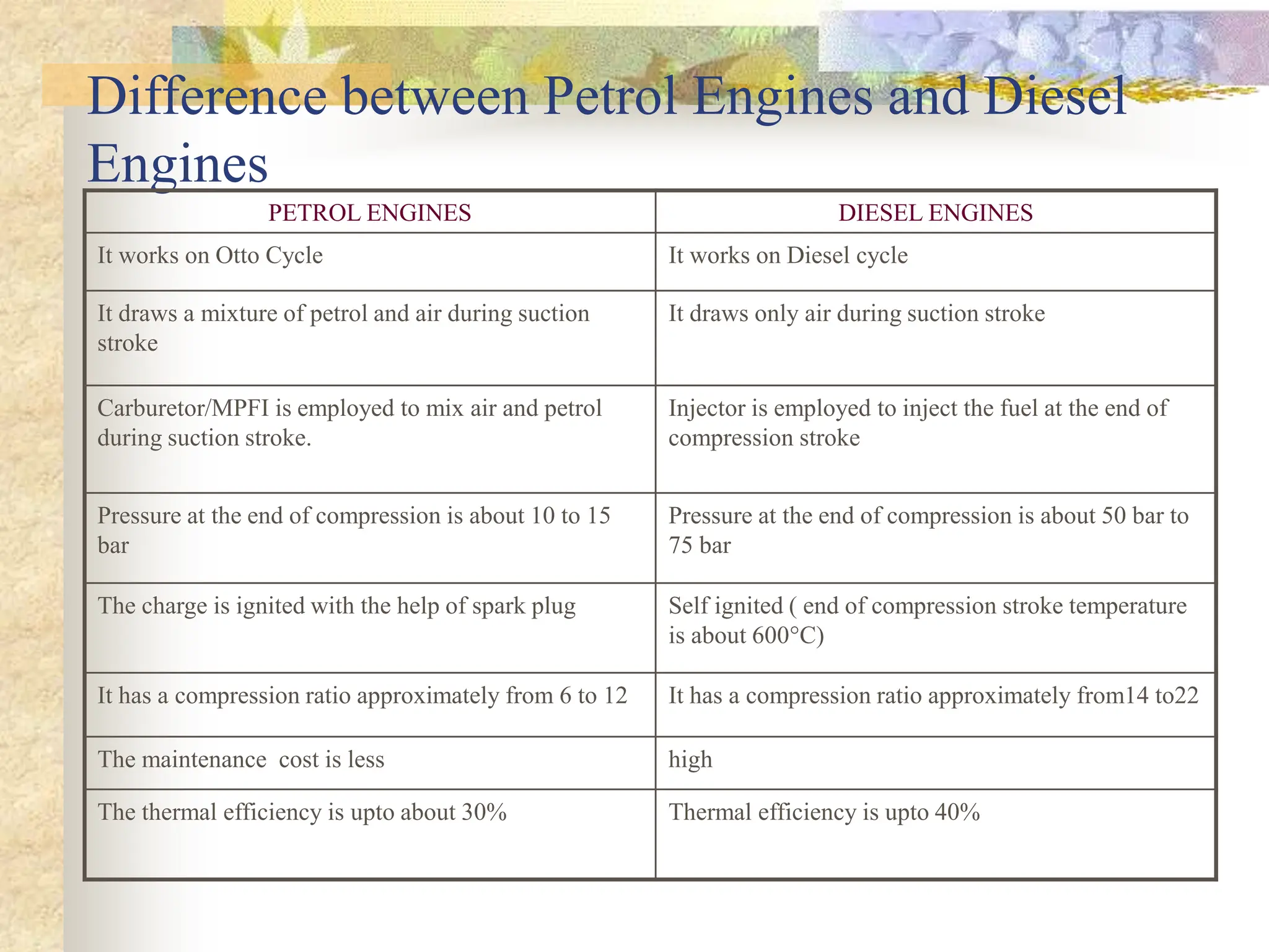
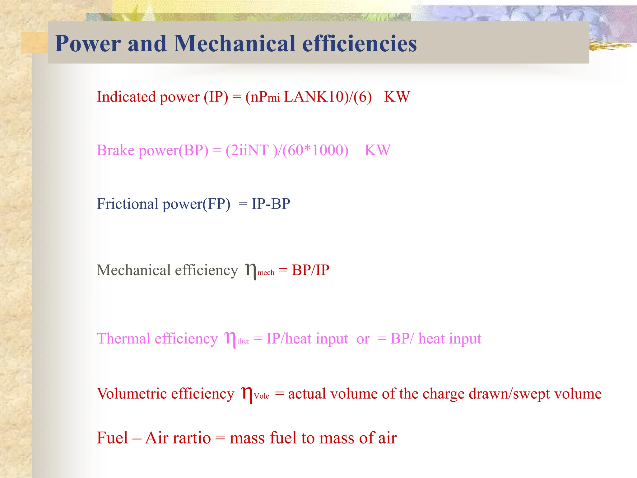
ME-420 Internal Combustion Engines
Introduction, Applications
&Classifications
Content
n Introduction
n Application of IC engines
n Parts of IC Engines
n Classification of IC Engines
n Working of IC Engines
n Difference between Two stroke and Four Stroke
n Difference between SI and CI Engines
Introduction
Internal Combustion Engines
Heat Engines
External Combustion Engines
Definition of Heat Engines :-
It is mechanical device , which converts heat
energy into mechanical energy
Example :- Gas turbine power plants ,
Steam power Plants,
Internal Combustion Engines(automobiles)
External combustion Engines
n Combustion takes
place away from
work producing
place
n Steam power plants
Internal Combustion Engines
Combustion takes Place inside the Cylinder
(i.e., with in the work producing place)
Example :- All Type of automobile engines
Basic Principle of IC Engines
Combustion Is Key
To understand the basic idea behind how a
reciprocating internal combustion engine
works, it is helpful to have a good mental
image of how "internal combustion" works.
One good example is an old Revolutionary
War cannon. You have probably seen
these in movies, where the soldiers load
the cannon with gun powder and a cannon
ball and light it. That is internal
combustion,
Application of Internal combustion Engines
n Road Vehicles
n Air Craft
n Locomotives
n Pumping sets
n Cinemas
n Hospital
n Several Industrial application
Automobile
engineering is the
activity of
designing and
constructing
automobiles
Back to Content
 1876 – Otto’s first prototype
 1st practical ICE
 Power: 2 hp; Weight: 1250 pounds
 Comp. ratio = 4 (knock limited), 14%
efficiency (theory 38%)
 Today CR = 9 (still knock limited),
30% efficiency (theory 55%)
 1881 – Two stroke engine
 1892 – Diesel’s first prototype
 1921 -Antiknock effect of
tetraethyl lead – General Motors
 1957 – Wankel’s first prototype
 1975 - Catalytic converters,
unleaded fuel
 1980s - Microcomputer control of
engines
Parts of an IC Engines (Petrol Engines)
Cylinder
Cylinder head
Piston and piston rings
Connecting Rod
Crank and Crankshaft
Inlet Valve
Exhaust Valve
Inlet manifold
Exhaust manifold
Cam and cam follower
push Rod and Rocker Arm
Crank Case
Flywheel
Carburetor
Spark plug
Parts of Diesel Engines
Basic Engine Nomenclature
Bore : Inside diameter of the cylinder
Top Dead Center : The extreme position of the piston at the top of the
cylinder(TDC)
Bottom Dead Center : The extreme position of the piston at the bottom of the
cylinder (BDC)
Stroke : The max distance traveled by the piston from TDC to BDC or vice versa
Clearance Volume : The volume contained in the cylinder above the top of the
piston When the piston at the TDC.
Piston Displacement or Swept Volume : The volume swept through by the piston
in moving from TDC to BDC.
Compression ratio : The ratio of the volume when the piston is at BDC to the
volume when the piston is at TDC
Back to Content
Classification of an IC Engines
n Based on Working Cycle
n Based on type of fuels used
n Based on Number of strokes
n Based on Cooling system
n Based on number of cylinders used
n Based on Cylinder arrangement
n Based on method of ignition
n Based on their application
n Based on method of Governing
Based on working Cycle
n Otto Cycle
n Ex :- Petrol Engines
n Diesel Cycle
n Ex : - Diesel Engines
n Duel Cycle
n Ex :- special purpose
engines
Based on types of fuel used
n Petrol Engines
n Diesel Engines
n Gaseous fuels Engines
Based on number of strokes
n Two Stroke Engines
n Power is getting in one revolution of the crank i.e., in two stroke
n Four Stroke Engines
n Power is getting in two revolution of the crank i.e., in four stroke
n Based on Cooling System
n Air cooling
n Water cooling
Back
The Two-stroke Cycle
Based on number of cylinder
n Single cylider Engines
n Multicylinder Engines
Based on Cylinder arrangements
n Inline Engines
n V – Type Engines
n Radial Engines
n Opposed piston Engines
n Opposed cylinder Engines
n Delta Type Engines
Based on method of ignition
n Spark Ignition Engines(SI Engines)
n Compression ignition(CI Engines)
Based on Cooling System
Air Cooling Engines
Water Cooling Engines
Based on Cylinder arrangement
Inline Engines V Type Engines
Radial Engines Opposed piston Engines Opposed cylinder Engines
Delta type
Based on Method of ignition
Spark ignition Engines
Compression Ignition Engines
Spark ignition
Based on Application
n Stationary Engines
n Marine Engines
n Portable Engines
n Automobile Engines
n Aero Engines
Based on method of Governing
n Hit & miss governed Engines
n Quality governed Engines
n Quantity governed Engines
Ignition system in diesel engines
Working of IC Engines
n Working of Two Stroke Engines
Petrol Engines
Diesel Engines
n Working of Four Stroke Engines
Petrol Engines
Diesel Engines
Working of Two stroke Diesel Engines
n Based on Diesel Cycle
n Fuel diesel
n Power is produced in every cycle
Working of two stroke diesel engines
Power is produced in one
revolution of the crank
shaft and suction,
compression, expansion
and exhaust stroke is
completed in two stroke
only.
Working of Two stoke petrol Engines
Working of Two stroke Petrol Engines
Back
Working of Four stroke Petrol Engines
Power is produced in four stroke
i.e.,two revolution of the crank
shaft
It work on Otto cycle and it completes
in four stroke of the piston
The cycle consisting of following
process
Suction stroke
Compression stroke
Expansion stroke or power stroke
Exhaust stroke
It requires carburetor and spark plug
Working of Four stroke Petrol Engines
Working of Four stroke diesel engines
Power is produced in four stroke
i.e.,two revolution of the crank
shaft
It work on Diesel Cycle and it
completes in four stroke of the
piston
The cycle consisting of following
process
Suction stroke
Compression stroke
Expansion stroke or power stroke
Exhaust stroke
It consists of fuel injection and
pumping arrangement
Working of Four stroke Diesel Engines
Difference between Two stroke and Four
Stroke Engines
Aspects Four Stroke Two Stroke
Completion of Cycle The cycle is completed in 4S of
the piston/ one power stroke in 2
revolution of the crank
The cycle is completed in 2S of
the piston/ one power stroke in 1
revolution of the crank
Flywheel required
(heavior or lighter)
Turning moment is not uniform
and hence heavier flywheel is
need
Turning moment is uniform and
hence lighter flywheel is need
Power Produced for some size of
engine
Is small or for the same power
the engine is heavy and bulky
Is more (2 Times ) or for the
same power the engine is light
and compact
Cooling and lubricants
requirements
Lesser cooling &lubricant More cooling and lubrication is
required
Valve and valve mechanism It contains valve and valve
mechanism
No valves
Initial cost Cost is high Initial cost is less
Difference between Two stroke and Four Stroke
Engines
Aspects Four Stroke Two Stroke
Volumetric efficiency more less
Thermal and part load
efficiencies
Higher and at part load efficiency
is more
Less and at part load efficiency
is less
application Cars, buses, truces, tractor ,
industrial application and etc..
Lawn movers, scooters, motor
cycles, and etc..
Difference between Petrol Engines and Diesel
Engines
PETROL ENGINES DIESEL ENGINES
It works on Otto Cycle It works on Diesel cycle
It draws a mixture of petrol and air during suction
stroke
It draws only air during suction stroke
Carburetor/MPFI is employed to mix air and petrol
during suction stroke.
Injector is employed to inject the fuel at the end of
compression stroke
Pressure at the end of compression is about 10 to 15
bar
Pressure at the end of compression is about 50 bar to
75 bar
The charge is ignited with the help of spark plug Self ignited ( end of compression stroke temperature
is about 600°C)
It has a compression ratio approximately from 6 to 12 It has a compression ratio approximately from14 to22
The maintenance cost is less high
The thermal efficiency is upto about 30% Thermal efficiency is upto 40%
Power and Mechanical efficiencies
Indicated power (IP) = (nPmi LANK10)/(6) KW
Brake power(BP) = (2iiNT )/(60*1000) KW
Frictional power(FP) = IP-BP
Mechanical efficiency ηmech = BP/IP
Thermal efficiency ηther = IP/heat input or = BP/ heat input
Volumetric efficiency ηVole = actual volume of the charge drawn/swept volume
Fuel – Air rartio = mass fuel to mass of air
***A course in Internal combustion engines
By V.M. Domkundwar
***A course in Internal combustion engines
By Mathur and sharma
*** Internal combustion engines
By V. Ganesan
*** auto.howstuffworks.com/engine.html/
*** Google search “ animation of working of
internal combustion engines “
Reference to this topic

IC ENGINE IC ENGINE IC ENGINE IC ENGINE IC ENGINE IC ENGINE IC ENGINE

  • 1.
    ME-420 Internal CombustionEngines Introduction, Applications &Classifications
  • 2.
    Content n Introduction n Applicationof IC engines n Parts of IC Engines n Classification of IC Engines n Working of IC Engines n Difference between Two stroke and Four Stroke n Difference between SI and CI Engines
  • 3.
    Introduction Internal Combustion Engines HeatEngines External Combustion Engines Definition of Heat Engines :- It is mechanical device , which converts heat energy into mechanical energy Example :- Gas turbine power plants , Steam power Plants, Internal Combustion Engines(automobiles)
  • 4.
    External combustion Engines nCombustion takes place away from work producing place n Steam power plants
  • 5.
    Internal Combustion Engines Combustiontakes Place inside the Cylinder (i.e., with in the work producing place) Example :- All Type of automobile engines
  • 6.
    Basic Principle ofIC Engines Combustion Is Key To understand the basic idea behind how a reciprocating internal combustion engine works, it is helpful to have a good mental image of how "internal combustion" works. One good example is an old Revolutionary War cannon. You have probably seen these in movies, where the soldiers load the cannon with gun powder and a cannon ball and light it. That is internal combustion,
  • 7.
    Application of Internalcombustion Engines n Road Vehicles n Air Craft n Locomotives n Pumping sets n Cinemas n Hospital n Several Industrial application
  • 8.
    Automobile engineering is the activityof designing and constructing automobiles
  • 9.
  • 10.
     1876 –Otto’s first prototype  1st practical ICE  Power: 2 hp; Weight: 1250 pounds  Comp. ratio = 4 (knock limited), 14% efficiency (theory 38%)  Today CR = 9 (still knock limited), 30% efficiency (theory 55%)  1881 – Two stroke engine  1892 – Diesel’s first prototype  1921 -Antiknock effect of tetraethyl lead – General Motors  1957 – Wankel’s first prototype  1975 - Catalytic converters, unleaded fuel  1980s - Microcomputer control of engines
  • 11.
    Parts of anIC Engines (Petrol Engines) Cylinder Cylinder head Piston and piston rings Connecting Rod Crank and Crankshaft Inlet Valve Exhaust Valve Inlet manifold Exhaust manifold Cam and cam follower push Rod and Rocker Arm Crank Case Flywheel Carburetor Spark plug
  • 12.
  • 13.
    Basic Engine Nomenclature Bore: Inside diameter of the cylinder Top Dead Center : The extreme position of the piston at the top of the cylinder(TDC) Bottom Dead Center : The extreme position of the piston at the bottom of the cylinder (BDC) Stroke : The max distance traveled by the piston from TDC to BDC or vice versa Clearance Volume : The volume contained in the cylinder above the top of the piston When the piston at the TDC. Piston Displacement or Swept Volume : The volume swept through by the piston in moving from TDC to BDC. Compression ratio : The ratio of the volume when the piston is at BDC to the volume when the piston is at TDC Back to Content
  • 14.
    Classification of anIC Engines n Based on Working Cycle n Based on type of fuels used n Based on Number of strokes n Based on Cooling system n Based on number of cylinders used n Based on Cylinder arrangement n Based on method of ignition n Based on their application n Based on method of Governing
  • 15.
    Based on workingCycle n Otto Cycle n Ex :- Petrol Engines n Diesel Cycle n Ex : - Diesel Engines n Duel Cycle n Ex :- special purpose engines
  • 16.
    Based on typesof fuel used n Petrol Engines n Diesel Engines n Gaseous fuels Engines Based on number of strokes n Two Stroke Engines n Power is getting in one revolution of the crank i.e., in two stroke n Four Stroke Engines n Power is getting in two revolution of the crank i.e., in four stroke n Based on Cooling System n Air cooling n Water cooling
  • 17.
  • 18.
    Based on numberof cylinder n Single cylider Engines n Multicylinder Engines Based on Cylinder arrangements n Inline Engines n V – Type Engines n Radial Engines n Opposed piston Engines n Opposed cylinder Engines n Delta Type Engines Based on method of ignition n Spark Ignition Engines(SI Engines) n Compression ignition(CI Engines)
  • 19.
    Based on CoolingSystem Air Cooling Engines Water Cooling Engines
  • 20.
    Based on Cylinderarrangement Inline Engines V Type Engines
  • 21.
    Radial Engines Opposedpiston Engines Opposed cylinder Engines Delta type
  • 22.
    Based on Methodof ignition Spark ignition Engines Compression Ignition Engines Spark ignition
  • 23.
    Based on Application nStationary Engines n Marine Engines n Portable Engines n Automobile Engines n Aero Engines Based on method of Governing n Hit & miss governed Engines n Quality governed Engines n Quantity governed Engines
  • 24.
    Ignition system indiesel engines
  • 25.
    Working of ICEngines n Working of Two Stroke Engines Petrol Engines Diesel Engines n Working of Four Stroke Engines Petrol Engines Diesel Engines
  • 26.
    Working of Twostroke Diesel Engines n Based on Diesel Cycle n Fuel diesel n Power is produced in every cycle
  • 27.
    Working of twostroke diesel engines Power is produced in one revolution of the crank shaft and suction, compression, expansion and exhaust stroke is completed in two stroke only.
  • 28.
    Working of Twostoke petrol Engines
  • 29.
    Working of Twostroke Petrol Engines Back
  • 30.
    Working of Fourstroke Petrol Engines Power is produced in four stroke i.e.,two revolution of the crank shaft It work on Otto cycle and it completes in four stroke of the piston The cycle consisting of following process Suction stroke Compression stroke Expansion stroke or power stroke Exhaust stroke It requires carburetor and spark plug
  • 31.
    Working of Fourstroke Petrol Engines
  • 32.
    Working of Fourstroke diesel engines Power is produced in four stroke i.e.,two revolution of the crank shaft It work on Diesel Cycle and it completes in four stroke of the piston The cycle consisting of following process Suction stroke Compression stroke Expansion stroke or power stroke Exhaust stroke It consists of fuel injection and pumping arrangement
  • 33.
    Working of Fourstroke Diesel Engines
  • 34.
    Difference between Twostroke and Four Stroke Engines Aspects Four Stroke Two Stroke Completion of Cycle The cycle is completed in 4S of the piston/ one power stroke in 2 revolution of the crank The cycle is completed in 2S of the piston/ one power stroke in 1 revolution of the crank Flywheel required (heavior or lighter) Turning moment is not uniform and hence heavier flywheel is need Turning moment is uniform and hence lighter flywheel is need Power Produced for some size of engine Is small or for the same power the engine is heavy and bulky Is more (2 Times ) or for the same power the engine is light and compact Cooling and lubricants requirements Lesser cooling &lubricant More cooling and lubrication is required Valve and valve mechanism It contains valve and valve mechanism No valves Initial cost Cost is high Initial cost is less
  • 35.
    Difference between Twostroke and Four Stroke Engines Aspects Four Stroke Two Stroke Volumetric efficiency more less Thermal and part load efficiencies Higher and at part load efficiency is more Less and at part load efficiency is less application Cars, buses, truces, tractor , industrial application and etc.. Lawn movers, scooters, motor cycles, and etc..
  • 36.
    Difference between PetrolEngines and Diesel Engines PETROL ENGINES DIESEL ENGINES It works on Otto Cycle It works on Diesel cycle It draws a mixture of petrol and air during suction stroke It draws only air during suction stroke Carburetor/MPFI is employed to mix air and petrol during suction stroke. Injector is employed to inject the fuel at the end of compression stroke Pressure at the end of compression is about 10 to 15 bar Pressure at the end of compression is about 50 bar to 75 bar The charge is ignited with the help of spark plug Self ignited ( end of compression stroke temperature is about 600°C) It has a compression ratio approximately from 6 to 12 It has a compression ratio approximately from14 to22 The maintenance cost is less high The thermal efficiency is upto about 30% Thermal efficiency is upto 40%
  • 37.
    Power and Mechanicalefficiencies Indicated power (IP) = (nPmi LANK10)/(6) KW Brake power(BP) = (2iiNT )/(60*1000) KW Frictional power(FP) = IP-BP Mechanical efficiency ηmech = BP/IP Thermal efficiency ηther = IP/heat input or = BP/ heat input Volumetric efficiency ηVole = actual volume of the charge drawn/swept volume Fuel – Air rartio = mass fuel to mass of air
  • 38.
    ***A course inInternal combustion engines By V.M. Domkundwar ***A course in Internal combustion engines By Mathur and sharma *** Internal combustion engines By V. Ganesan *** auto.howstuffworks.com/engine.html/ *** Google search “ animation of working of internal combustion engines “ Reference to this topic