Downloaded 897 times
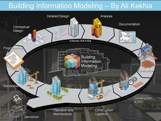
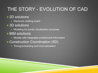
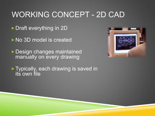
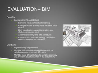
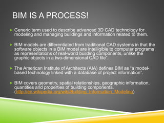
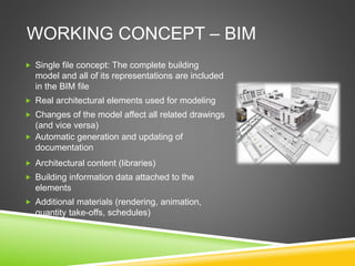
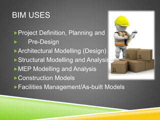
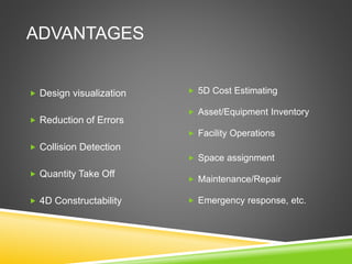
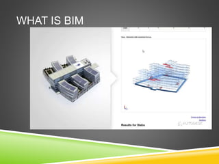
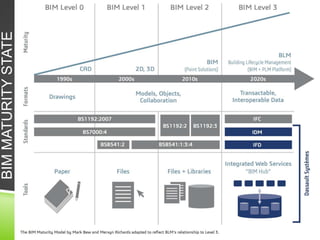


The document discusses the evolution of CAD and BIM technologies in building design, detailing the progression from traditional 2D drafting to advanced Building Information Modeling (BIM). It highlights the benefits and drawbacks of each technology, including increased efficiency, visualization capabilities, and automatic updates in BIM, contrasted with the limitations of 2D and 3D CAD processes. BIM is presented as a model-based technology that significantly improves project management by integrating architectural information, which enhances collaboration and reduces errors across all project stages.