Downloaded 258 times
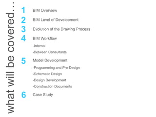


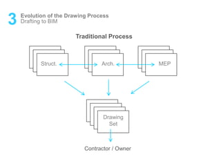
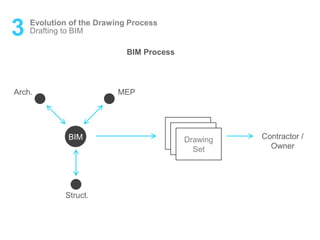


This document provides a comprehensive overview of Building Information Modeling (BIM) for project managers, detailing the evolution of the drawing process, the workflow involved, and the various levels of development for BIM. It highlights the significance of BIM in improving interoperability within the construction industry and outlines the roles of multiple stakeholders throughout the project lifecycle. Additionally, it discusses case studies and offers guidance on best practices for efficient model development and team collaboration.