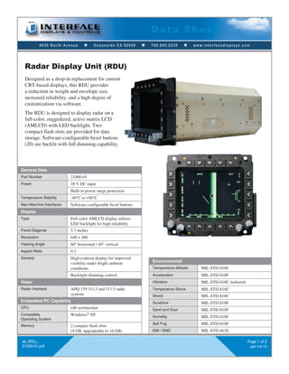
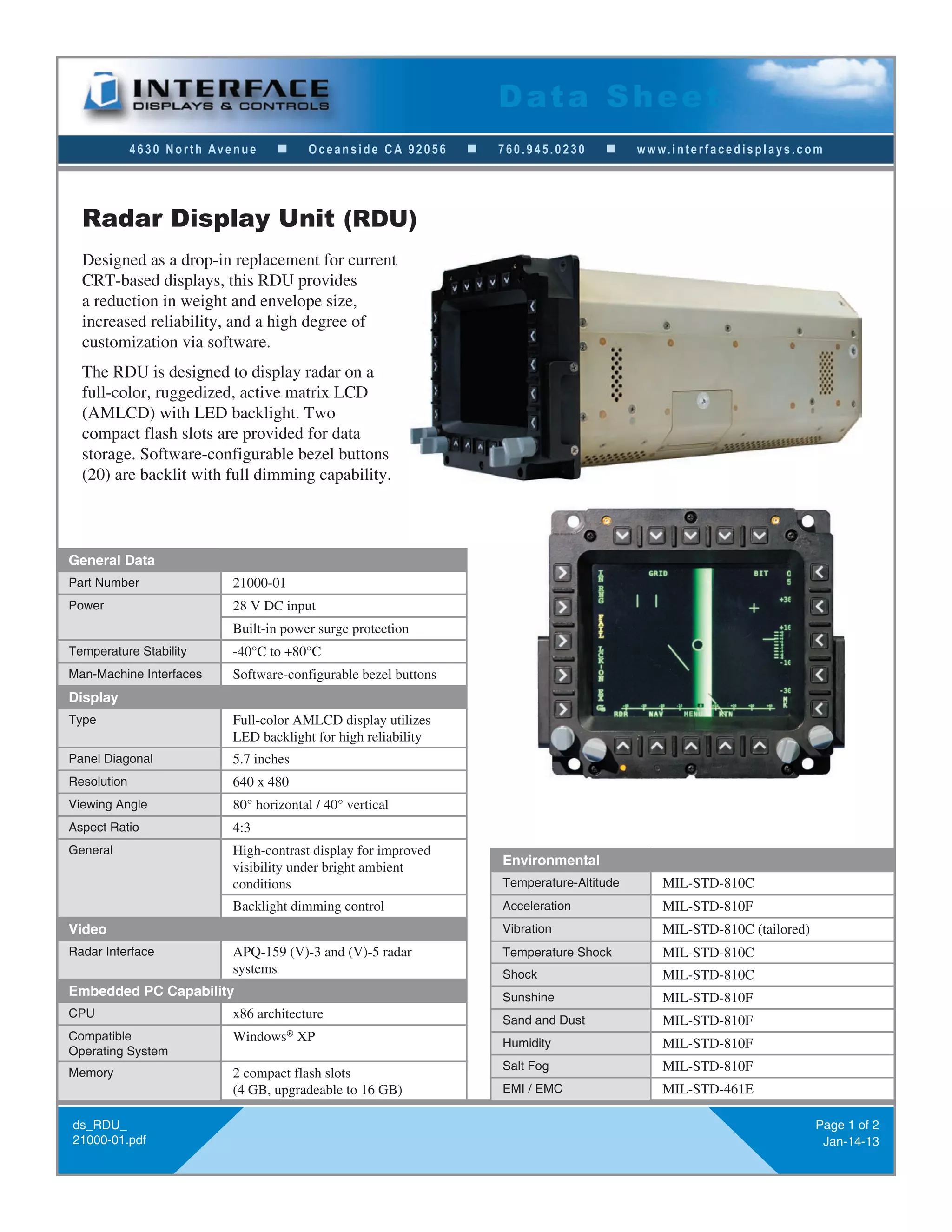
Radar Display Unit (RDU) Data Sheet (Interface Displays)
1. 4630 North Avenue n Oceanside CA 92056 n 760.945.0230 n www.interfacedisplays.com
Data Sheet
ds_RDU_
21000-01.pdf
Page 1 of 2
Jan-14-13
Designed as a drop-in replacement for current
CRT-based displays, this RDU provides
a reduction in weight and envelope size,
increased reliability, and a high degree of
customization via software.
The RDU is designed to display radar on a
full-color, ruggedized, active matrix LCD
(AMLCD) with LED backlight. Two
compact flash slots are provided for data
storage. Software-configurable bezel buttons
(20) are backlit with full dimming capability.
Radar Display Unit (RDU)
General Data
Part Number 21000-01
Power 28 V DC input
Built-in power surge protection
Temperature Stability -40°C to +80°C
Man-Machine Interfaces Software-configurable bezel buttons
Display
Type Full-color AMLCD display utilizes
LED backlight for high reliability
Panel Diagonal 5.7 inches
Resolution 640 x 480
Viewing Angle 80° horizontal / 40° vertical
Aspect Ratio 4:3
General High-contrast display for improved
visibility under bright ambient
conditions
Backlight dimming control
Video
Radar Interface APQ-159 (V)-3 and (V)-5 radar
systems
Embedded PC Capability
CPU x86 architecture
Compatible
Operating System
Windows®
XP
Memory 2 compact flash slots
(4 GB, upgradeable to 16 GB)
Environmental
Temperature-Altitude MIL-STD-810C
Acceleration MIL-STD-810F
Vibration MIL-STD-810C (tailored)
Temperature Shock MIL-STD-810C
Shock MIL-STD-810C
Sunshine MIL-STD-810F
Sand and Dust MIL-STD-810F
Humidity MIL-STD-810F
Salt Fog MIL-STD-810F
EMI / EMC MIL-STD-461E
2. 4630 North Avenue n Oceanside CA 92056 n 760.945.0230 n www.interfacedisplays.com
Data Sheet
ds_RDU_
21000-01.pdf
Page 2 of 2
Jan-14-13
RDU Pin-out
Pin Signal Pin Signal
53 0-5VAC 18 DC RTN
52 0-5VAC RTN 10 TV VIDEO (COAX)
50 28VDC 3 CHASSIS GND
51 28VDC RTN 5 SPARE
20 PERSISTANCE 7 SPARE
21 FREEZE 32 PITCH TRIM
56 TEST 30 VIDEO GAIN
35 28VDC RDR ON/OFF 58 GAMMA OVERRIDE
TBD TO J3 OF RADAR PROCESSOR (RP) PIN Y; VIDEO CLAMP
TBD TO J3 OF RP PIN Z; VIDEO CLAMP RTN
TBD TO J3 OF RP PIN D; INTENSITY GATE
TBD TO J3 OF RP PIN GG; ANTENNA DIRECTION
TBD TO J1 OF RP PIN a; TRACK INTENSITY GATE
TBD TO J1 OF RP PIN c; INDICATOR TRACKER VIDEO
(A)
(A)
COMPACT FLASH ACCESS
DOOR BOTH SIDES(A)(A)
(A)
PILOT FINGER GRIP
2 PLACES
(A)(A)
(A)
(A)
(A)
(A)
(A)
(A)
(A)
(A)(A)
(A)
(A)
(A)
(A)
(A) (A) (A)
(A)
(A)
(A)
(A)
(A)
Right Side
Back
Front
(A) Dimensions available upon request.