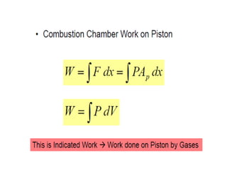
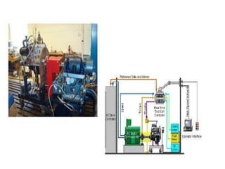
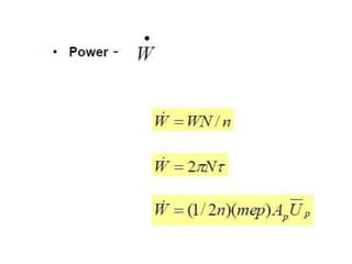
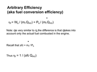
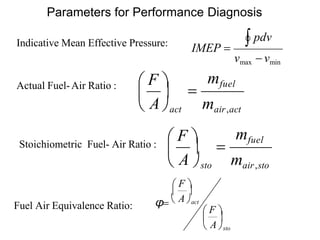
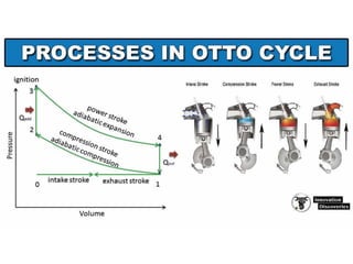
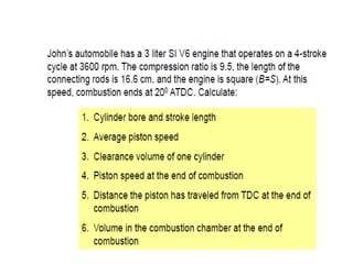
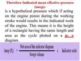
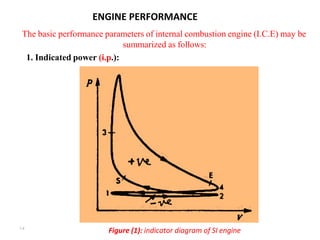
1. The document discusses key parameters for analyzing engine performance such as power, torque, mean effective pressure, efficiency, and fuel consumption.
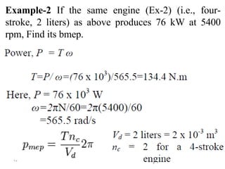
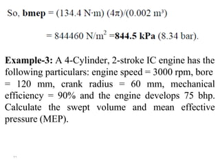
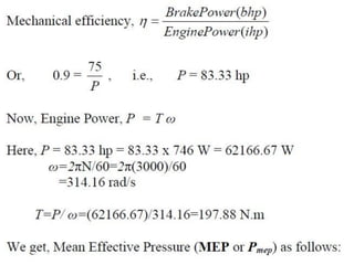
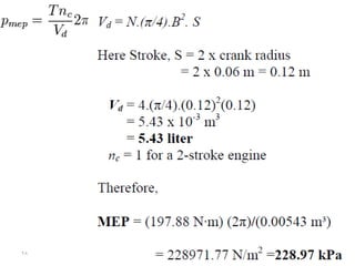
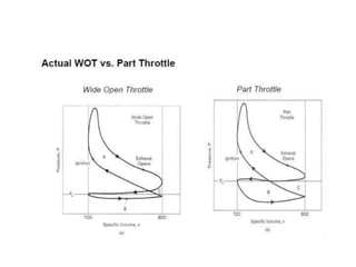
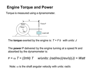
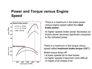
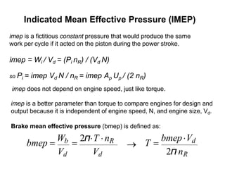
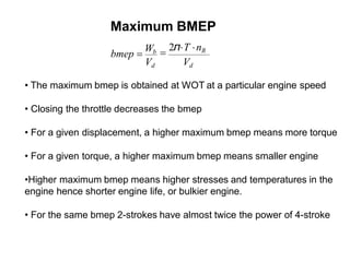
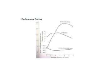
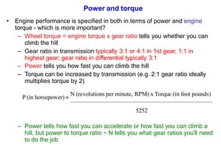
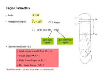
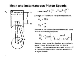
2. Engine performance is specified by both power and torque. Power tells you how fast you can accelerate while torque tells you whether you can overcome resistance like climbing a hill.
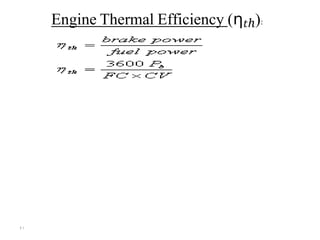
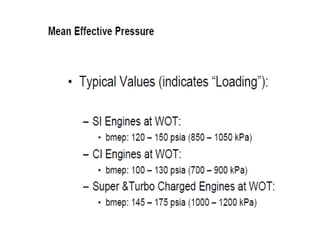
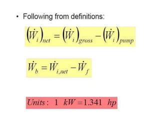
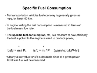
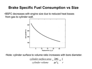
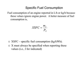
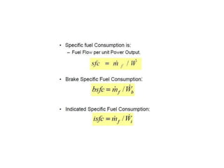
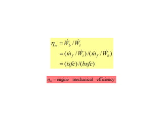
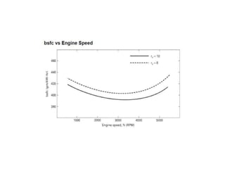
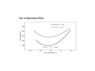
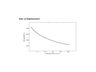
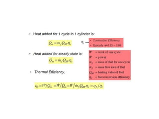
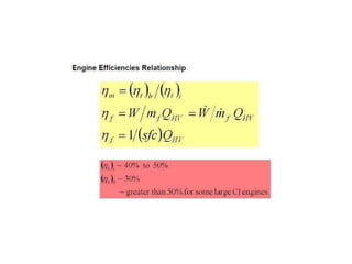
3. Other important parameters discussed include indicated mean effective pressure, brake mean effective pressure, mechanical efficiency, specific fuel consumption, and thermal efficiency.
![۲
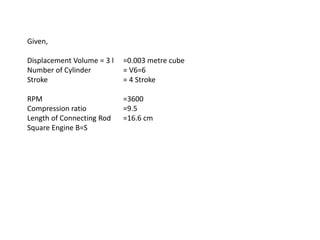
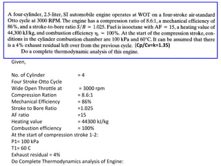
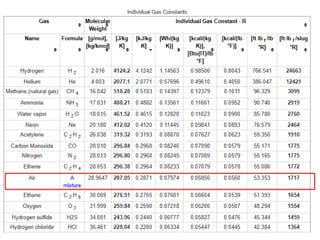
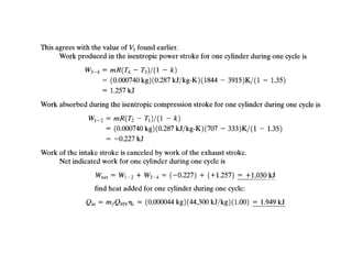
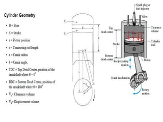
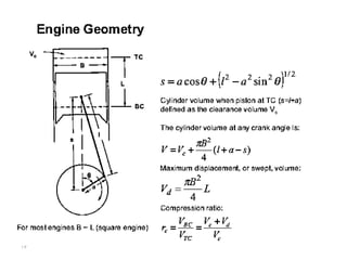
Cylinder Swept Volume (Vc):
where:
Vc= cylinder swept volume [cm3 (cc) or L]
Ac = cylinder area [cm2 or cm2/100]
dc = cylinder diameter [cm or cm/10]
L = stroke length (the distance between the TDC and
BDC) [cm or cm/10]
BDC = Bottom Dead Center
TDC = Top Dead Center
The units of cylinder swept volume is measured in (cm3, cubic
centimeter (cc), or liter).](https://image.slidesharecdn.com/chapter-6-lecture-final-engine-performance-240408192814-50455003/85/Chapter-6-lecture-final-Engine-performance-pdf-9-320.jpg)
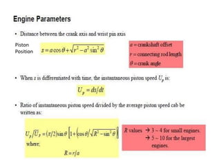
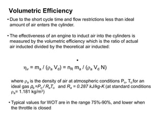
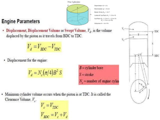
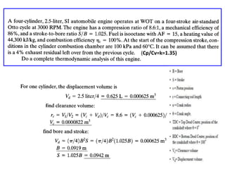
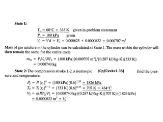
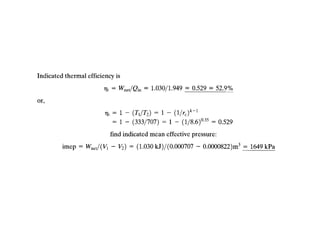
![Compression Ratio (r):
where:
r = compression ratio
Vs = cylinder swept volume (combustion chamber volume) [cc,
L, or m3] it is design parameter
Vc = cylinder volume [cc, L, or m3] it is design paramete
* Increase the compression ratio increase engine power
- r (gasoline engine) = 7:12, the upper limit is engine pre ignition
- r (diesel engine) = 10:18, the upper limit is the stresses on
٥engine parts](https://image.slidesharecdn.com/chapter-6-lecture-final-engine-performance-240408192814-50455003/85/Chapter-6-lecture-final-Engine-performance-pdf-12-320.jpg)
![٦
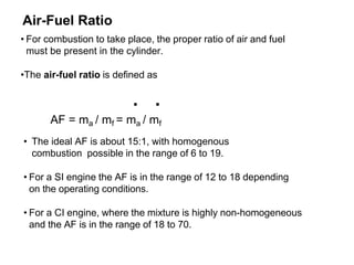
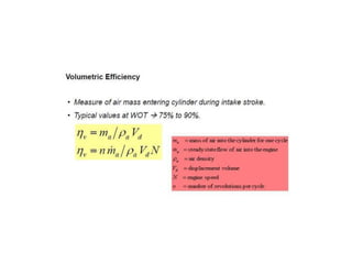
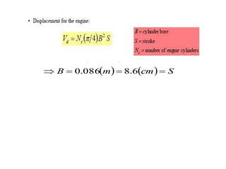
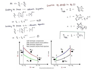
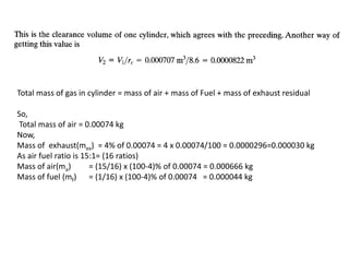
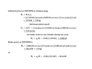
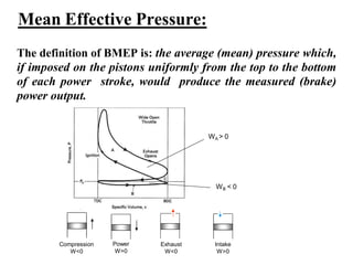
Engine Volumetric Efficiency (hv):
where: ηV = volumetric efficiency
Vair = volume of air taken into cylinder [cc, L, or m3]
Vc = cylinder swept volume [cc, L, or m3]
* Increase the engine volumetric efficiency increase engine
power
- Engine of normal aspiration has a volumetric efficiency of
80% to 90%
- Engine volumetric efficiency can be increased by using:
(turbo and supper charger can increase the volumetric
efficiency by 50%)](https://image.slidesharecdn.com/chapter-6-lecture-final-engine-performance-240408192814-50455003/85/Chapter-6-lecture-final-Engine-performance-pdf-13-320.jpg)
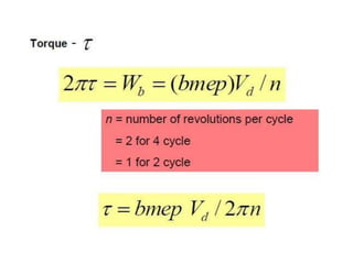
![۱٦
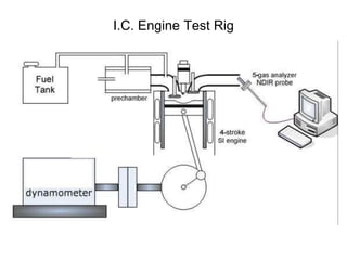
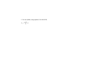
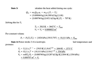
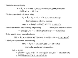
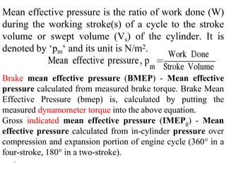
Engine Indicated Torque (Ti):
where:
Ti = engine indicated torque [Nm]
imep = indicated mean effective pressure [N/m2]
Ac = cylinder area [m2]
L = stroke length [m]
z = 1 (for 2 stroke engines), 2 (for 4 stroke engines)
n = number of cylinders
θ = crank shaft angle [1/s]](https://image.slidesharecdn.com/chapter-6-lecture-final-engine-performance-240408192814-50455003/85/Chapter-6-lecture-final-Engine-performance-pdf-22-320.jpg)
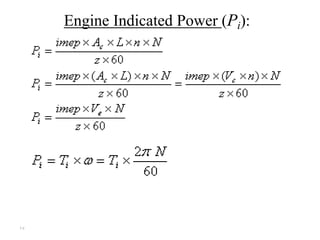
![۱۸
where:
imep = is the indicated mean effective pressure
[N/m2],
Ac = cylinder area [m2],
L = stroke length [m],
n = number of cylinders,
N = engine speed [rpm],
z = 1 (for 2 stroke engines), 2 (for 4 stroke engines),
Vc = cylinder swept volume [m3],
Ve = engine swept volume [m3],
Ti = engine indicated torque [Nm], and
ω = engine angular speed [1/s]](https://image.slidesharecdn.com/chapter-6-lecture-final-engine-performance-240408192814-50455003/85/Chapter-6-lecture-final-Engine-performance-pdf-24-320.jpg)
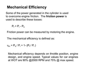
![۱۹
Engine Mechanical Efficiency (ηm):
where:
m = mechanical efficiency
Pb = engine brake power [kW]
Pi = engine indicated power [kW]
Pf = engine friction power [kW]](https://image.slidesharecdn.com/chapter-6-lecture-final-engine-performance-240408192814-50455003/85/Chapter-6-lecture-final-Engine-performance-pdf-25-320.jpg)
![۲۰
Engine Specific Fuel Consumption (SFC):
where:
SFC = specific fuel consumption
[(kg/h)/kW, kg/(3600 s x kW=kJ/s), kg/(3600
kJ)]
FC= fuel consumption [kg/h]
Pb = brake power [kW]](https://image.slidesharecdn.com/chapter-6-lecture-final-engine-performance-240408192814-50455003/85/Chapter-6-lecture-final-Engine-performance-pdf-26-320.jpg)